Alma Mater Studiorum
· Universit`a di Bologna
SCUOLA DI SCIENZE Corso di Laurea in Informatica
An Updated Emulated Architecture
to Support the Study
of Operating Systems
Relatore:
Prof. Renzo Davoli
Correlatore:
Prof. Michael Goldweber
Presentata da:
Mattia Biondi
Sessione Straordinaria
Anno Accademico 2018/2019
Agli amici di sempre,
alla mia famiglia,
che non mi ha mai impedito nulla,
e a Jas,
senza la quale non sarei qui oggi.
Abstract
One of the most effective ways to learn something new is by actively practising it, and there is—maybe—no better way to study an Operating Systems course than by building your own OS.
However, it is important to emphasize how the realization of an operating system capable of running on a real hardware machine could be an overly complex and unsuitable task for an undergraduate student. Nonetheless, it is possible to use a simplified computer system simulator to achieve the goal of teaching Computer Science foundations in the University environment, thus allowing students to experience a quite realistic representation of an operating system.
µMPS has been created for this purpose, a pedagogically appropriate machine emulator, based around the MIPS R2/3000 microprocessor, which features an accessible architecture that includes a rich set of easily pro-grammable devices. µMPS has an almost two decades old historical de-velopment and the outcome of this following thesis is the third version of the software, dubbed µMPS3. This second major revision aims to simplify, even more, the complexity of the emulator in order to lighten the load of work required by the students during the OS design and implementation. Two of these simplifications are the removal of the virtual memory bit, which al-lowed address translation to be turned on and off, and the replacement of the tape device, used as storage devices, with a new flash drive device—certainly something more familiar to the new generation of students.
Thanks to the employment of this software and the feedback received over the last decade, it has been possible to realize not just this following thesis, but also to develop some major improvements, which concern everything from the project building tools to the front-end, making µMPS a modern and reliable educational software.
Sommario
Uno dei metodi pi`u efficaci per imparare qualcosa di nuovo `e facendo pra-tica, e probabilmente, non esiste modo migliore di studiare un corso di Siste-mi Operativi, se non scrivendo il proprio SO. `E tuttavia necessario prendere atto di quanto la realizzazione di un sistema operativo, in grado di girare su una vera macchina hardware, sia un compito eccessivamente complesso e quasi inadeguato per uno studente universitario. Ci`o non toglie che sia per`o possibile far uso di simulatori di sistemi semplificati rispetto alla realt`a, al fine di riuscire nell’insegnamento dei fondamenti dell’Informatica in con-testi universitari, permettendo cos`ı agli studenti di sperimentare con una rappresentazione di un sistema operativo abbastanza realistica.
µMPS `e stato sviluppato proprio a questo scopo, un emulatore di sistemi pedagogicamente appropriato, basato sul microprocessore MIPS R2/3000, e dotato di un’architettura accessibile e di una ricca lista di dispositivi fa-cilmente programmabili. µMPS conta quasi vent’anni di sviluppo, ora ag-giornato tramite la seguente tesi alla sua terza versione, chiamata µMPS3. Quest’ultimo aggiornamento mira a semplificare, ancor di pi`u, la complessit`a dell’emulatore, al fine di alleggerire il carico di lavoro richiesto agli studenti durante lo sviluppo e l’implementazione del sistema operativo. Due di queste semplificazioni sono la rimozione del bit di memoria virtuale, che permetteva l’attivazione e la disattivazione della traduzione di indirizzi, e la sostituzione dei nastri, utilizzati come dispositivi di archiviazione, con delle nuove unit`a di memoria flash—certamente pi`u familiari alla nuova generazione di studenti. Grazie all’utilizzo di questo software e dei feedback ricevuti, nel corso degli ultimi dieci anni, `e stato possibile non solo realizzare la seguente tesi, ma anche apportare alcune importanti migliorie che riguardano tutti i campi, dagli strumenti di compilazione del progetto alla parte front-end, rendendo cos`ı µMPS un software pedagogico moderno e affidabile.
Contents
1 Introduction 1
1.1 Background . . . 1
1.2 History of µMPS . . . 2
1.3 µMPS3 . . . 3
1.4 Structure of the Document . . . 5
2 Memory Management 7 2.1 Physical Memory . . . 7
2.1.1 BIOS Reserved Space . . . 8
2.1.2 RAM Space . . . 10 2.2 Virtual Memory . . . 10 2.2.1 TLB Floor Address . . . 12 2.3 Previous Implementation . . . 13 2.4 VM Bit Removal . . . 14 3 Exception Handling 17 3.1 Processor Actions on Exception . . . 19
3.2 BIOS Data Page . . . 20
3.2.1 BIOS Exception Handlers . . . 21
3.3 Previous Implementation . . . 21
3.3.1 ROM Reserved Frame . . . 22
CONTENTS CONTENTS 4 Multiprocessor Support 25 4.1 Processors Initialization . . . 25 4.1.1 Processor 0 . . . 26 4.1.2 Processors 1-15 . . . 26 5 Device Interfaces 29 5.1 Tape drives . . . 29 5.2 Flash Drives . . . 30 5.2.1 Creation . . . 32 5.2.2 Usage . . . 33
6 Project Structure Update 37 6.1 Build System . . . 37
6.1.1 CMake . . . 38
6.2 Graphical User Interface . . . 39
6.2.1 Qt5 . . . 40
6.2.2 Logo and Icon Theme . . . 40
6.2.3 Other Improvements . . . 41
7 Conclusions 45 7.1 Future Work . . . 46
7.1.1 Software Packaging . . . 46
7.1.2 Persistent Debugging Settings . . . 47
7.1.3 Better Block Devices Creation . . . 48
List of Figures
2.1 Physical Memory . . . 8
2.2 Structure of the BIOS Reserved Space . . . 9
2.3 Virtual Memory Structure . . . 11
2.4 TLB Floor Address . . . 12
2.5 Old Virtual Memory Structure . . . 13
3.1 BIOS Data Page . . . 20
3.2 ROM Reserved Frame . . . 22
5.1 Flash Device COMMAND Field . . . 35
5.2 Flash Device DATA1 Field . . . 36
6.1 µMPS3 Logo . . . 41
6.2 Edit Configuration Menu Entry . . . 42
6.3 Clear Recent Menu Entry . . . 42
6.4 Reset Shortcut . . . 43
6.5 RAMTOP value . . . 43
List of Tables
2.1 Bus Register Area . . . 15
4.1 Processor Interface Registers . . . 25
5.1 Device Register Layout . . . 34
5.2 Flash Device Status Codes . . . 34
5.3 Flash Device Command Codes . . . 35
6.1 Start and Halt icons . . . 40
Listings
2.1 TLB Floor Address . . . 16
Notational Conventions
• Words being defined are italicized;• A typewriter-like typeface is used for memory addresses, machine registers, instructions, file names, identifiers, and code fragments;
• Memory addresses and operation codes are given in hexadecimal and displayed in big-endian format;
• Bits of storage are numbered right-to-left, starting with 0;
• All diagrams illustrating memory are going from low addresses to high addresses, using a left to right, bottom to top orientation.
Chapter 1
Introduction
1.1
Background
The study and the consequent implementation of how an operating sys-tem works is, by now, a long-established and consolidated practice in many Computer Science curriculum. It is, actually, one of the crucial components of a computer and it is responsible for ensuring its basic operations, by coor-dinating and managing the system resources like processor, memory, devices and processes, thus allowing hardware and software to interface each other.
This is probably the first real example of “big project” which students should experience, thanks to the complex intercommunication system that has to exist between the different components of the machine, and the study of it allows to comprehend the most common software engineering practices. The approach on practical contexts is essential to fully understand how a machine works behind the theoretical notions studied in the early stages of the course of study, and it is usually followed by the debate of which is the best teaching choice concerning processor architectures.
Obviously, there is not only one way of how a central processor unit can be implemented, and while older realizations—although applicable for educa-tional purposes—are now obsolete and incompatible with current platforms, modern ones are designed to achieve high speed and quality, which makes
2 1. Introduction
them overly complex and unsuitable for the pedagogic experience.
Over the years, the MIPS architecture has become one of the landmarks in this teaching choice due to its clean and elegant instruction set, despite being excessively convoluted to student’s perception, because of the high level of details obscuring the basic underlying features of it. A potential solution to this problem is the adoption of a simplified computer system simulator, like µMPS, to bring together an adequate level of understanding and a realistic representation of a real operating system.
1.2
History of µMPS
µMPS is based on the machine emulator MPS [4], designed and realized by Professor Renzo Davoli and one of his graduate students Mauro Morsiani, in the late 1990s at the University of Bologna.
MPS, in turn, was created with the intention of recreating the same asset that a previous, fell out of use, machine emulator provided. CHIP [1, 2] (Cornell Hypothetical Instruction Processor) was its name, developed at the Cornell University and based on a made-up architecture that was a cross between a PDP-11 and an IBM S/370. The operating system designated to run on it was named HOCA [3], a three phase/layer project, named after the Turkish word hoca (“schoolmaster” or “giver of good advice”) which was proposed by one of its author, ¨Ozalp Babao˘glu, who is currently teaching at the University of Bologna.
The initial purpose of MPS was to bring back to life the layout and implementation experience of an operating system through an educational emulator, which could be run on real hardware. This practice was already possible in the past years when the architecture of the processor studied was the same available on real machines, but it has gone lost through the years because of the high-speed development of new and more complex technologies used on physical implementations.
1.3 µMPS3 3
other different device categories: disks, tapes, network adapters, printers and terminals. In addition, the Hoca project was updated and adapted to the new MPS architecture.
The concerned CPU was genuinely emulated together with its complex virtual memory management system, which was the main subject of the feedback received during class testing of MPS as a pedagogical tool at the University of Bologna and Xavier University, in an undergraduate operating systems courses, taught respectively by Renzo Davoli and Michael Goldwe-ber.
It was tested through the implementation of a direct descendant of HOCA, Kaya [5], one of the variety of graduate-level projects that the emulator can support.
The urge of simplification led to the creation of µMPS, virtually identical to MPS but with the addition of a virtual memory management subsystem which had to resemble as much as possible to the conceptual one found in popular introductory OS texts. The only other difference was the new novice-friendly graphical user interface, significantly improved again in 2011 by Tomislav Jonjic during the development of the first major revision of the emulator, µMPS2 [6], which also implemented the support to up to sixteen MIPS R3000-style processors.
1.3
µMPS3
More than ten years have passed since the first release of µMPS and as many have passed from the moment it has been developed into a consolidated educational tool. At its peak, it was adopted by more than 50 institutions, proving that its initial purpose had been achieved.
Over time, this number has decreased, showing that a refresh of the tool was needed to regain the attention of new generations of OS instructors. The students’ observations during this period of use were essential to understand which of these further changes were required to give µMPS a new life as an
4 1. Introduction
useful pedagogical tool.
Some examples of these modifications would be the structure and man-agement system of both physical and virtual memory, a nuance probably still too complex and confusing, which could feel like a regression, since the at-tempt to simplify it has led to the removal of the VM bit. This was originally introduced in the first version of µMPS, as a distinctive feature from its pre-decessor MPS. Virtual memory segmentation has been eliminated too, since it is considered as legacy in current architectures, making its implementation an unnecessary complication for the students.
There are also other changes related to the passage of the years, such as the replacement of memory tapes with flash drive devices, also known as “USB sticks”, “SD Cards” or even “SSDs”. Tapes are probably still studied in their operation nowadays, but they cannot be found in today’s practical contexts, and therefore it could be difficult to understand for the new generation of students, who cannot find a match in current technological implementations.
Another consequence of the update of µMPS has been the shift from the historical and well established Autotools to a more current building tool, CMake, that speeds up the compilation process in addition to simplifying the structure of the project. It also fits best with the current graphical user interface of the emulator, originally built upon Qt4, which also undergoes to the migration to the new version, Qt5.
These and more changes are collected together in a major release of the project, µMPS3, consequently bringing even more reliability in terms of ped-agogical tool.
Due to implementation aspects—unlike its predecessor µMPS2—this new version is not backward compatible with older versions.
1.4 Structure of the Document 5
1.4
Structure of the Document
This thesis will primarily focus on the modifications made on the previous version of the emulator, their implementation and the reasons to do it. This document is not intended to be used as a substitute of the manual µMPS3 Principles of Operation [7], but only as an accompanying guide to understand how the two versions differ from each other.
This first chapter aims to give a brief overview of why tools like µMPS are needed, its history to date and the considerations on why an update was necessary.
Chapter 2 and 3 will respectively describe the new memory management, as both physical and virtual ones have been updated, and the new exception handling mechanism. Both current and previous implementations will be compared in every aspect.
Chapter 4 will explain the advanced feature of the multiprocessor support. The CPUs initialization has been updated to comply with the new exception handling.
Chapter 5 is an introduction of the new flash device, which takes over tapes. The reasons why this replacement was necessary are described in the first part of the chapter, while the rest of the chapter illustrates its creation and its usage.
Chapter 6 is the less technical one, since it describes the migration from the old project building tool to the new one, and the renewal of the graphical user interface.
Finally, chapter 7 will provide a brief summary of the topics covered by this thesis and the reasons for the changes made. A shortlist of possible future implementation is also given.
Chapter 2
Memory Management
Like for the two prior versions, the memory subsystem of µMPS3 is di-vided into two views: physical and virtual. Both parts have undergone sig-nificant modifications in this major revision, and they will be described in detail in this chapter, alongside their old versions and respective changes.
The main reasons for the modifications made are the further simplification of the work required by the user for the kernel implementation and the better clarification of the internal view of the emulator memory, which, in the past, have caused some difficulties to the students.
2.1
Physical Memory
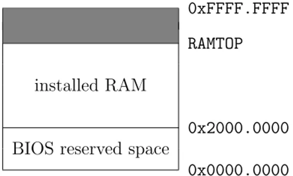
The physical address space is divided into two big areas [Figure 2.1]: a BIOS reserved space, from address 0x0000.0000 to 0x2000.0000, and the installed RAM, from address 0x2000.0000 (RAMBASE) to RAMTOP.
This last value is calculated upon the one retrieved from the configuration file, settable from the configuration dialog of the machine in the front-end emulator, which goes from a minimum of 8 to a maximum of 512 memory frames. Being the size of each frame 4 kilobyte, µMPS3 can have from 32KB up to 2MB of installed RAM. Hence, the value of RAMTOP range from 0x2000.8000 to 0x2020.0000.
8 2. Memory Management
0xFFFF.FFFF
RAMTOP
installed RAM
0x2000.0000 BIOS reserved space
0x0000.0000
Figure 2.1: Physical Memory
2.1.1
BIOS Reserved Space
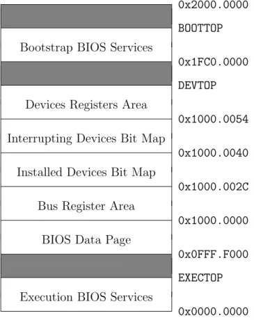
The first big area of the memory [Figure 2.2] is reserved for:
• the Execution BIOS Services [7], which lay in a read-only segment from address 0x0000.0000 to EXECTOP. This latter value is calculated upon the size of the Execution BIOS Services code;
• the BIOS Data Page, from address 0x0FFF.F000 (BIOSDATABASE) to 0x1000.0000. This is the same 4KB area that was used to be called “ROM Reserved Frame” [subsection 3.3.1] in µMPS2, which has been renamed and moved. However, it still serves as an interface between the BIOS handlers [subsection 3.2.1] and the user-implemented kernel. See section 3.2 for more information regarding how this read/writable area segment has been updated;
• the Bus Register Area, from address 0x1000.0000 to 0x1000.002C: a 11 word area containing various fields used in the lifetime cycle of µMPS3 to properly work. Some of them are read-only and calculated at boot/reset time, while others are read/writable. See [7] for more information regarding this area;
• the Installed Devices Bit Map, from address 0x1000.002C to
0x1000.0040: a read-only five word area indicating which devices are actually installed and where [7];
2.1 Physical Memory 9
• the Interrupting Devices Bit Map, from address 0x1000.0040 to 0x1000.0054: a read-only five word area indicating which devices have an interrupt pending [7];
• the Devices Registers Area, from address 0x1000.0054 to 0x1000.02D4 (DEVTOP): a 160 word area (number of interrupt lines (8)× devices per interrupt line (5) × words per register (4)). See [7] for more informa-tion, or Table 5.1 for an example of one device register;
• the Bootstrap BIOS Services [7], which lay in a read-only segment from address 0x1FC0.0000 to BOOTTOP. This latter value is calculated upon the size of the Bootstrap BIOS Services code.
0x2000.0000
BOOTTOP Bootstrap BIOS Services
0x1FC0.0000
DEVTOP Devices Registers Area
0x1000.0054 Interrupting Devices Bit Map
0x1000.0040 Installed Devices Bit Map
0x1000.002C Bus Register Area
0x1000.0000 BIOS Data Page
0x0FFF.F000
EXECTOP Execution BIOS Services
0x0000.0000
10 2. Memory Management
Any attempt to access an undefined memory area (EXECTOP...0x0FFF.F000, DEVTOP...0x1FC0.0000, BOOTTOP...0x2000.0000) will generate a Bus Er-ror exception [chapter 3].
Note: the memory area between address 0x1000.02D4 (DEVTOP) and 0x1FC0.0000 is not completely undefined [section 7.3 of the old manual [8]].
2.1.2
RAM Space
The maximum RAMTOP value actually settable is 0x2020.0000. However, since µMPS3 uses 32-bit addresses, it could support up to [232 - RAMBASE] ' 3.5GB of RAM. The 2MB graphical user interface limitation is imposed because, while it seems a ridiculously small amount of memory in today’s ordinary systems, it is, actually, a lot more than has ever been required in all these years of µMPS use.
This area will hold:
• the code (text), global variables/structures (data), and stack(s) of the operating system;
• enough space for the “frame pool” to be used for the text, data and stacks of the user processes during virtual memory management.
As for the previous big area, any attempt to access the undefined memory area laying from RAMTOP up to 0xFFFF.FFFF will generate a Bus Error ex-ception.
2.2
Virtual Memory
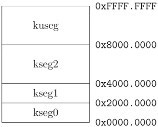
While the physical one is divided into two big areas, the virtual memory subsystem is logically split into four units [Figure 2.3]:
• kseg0, from address 0x0000.0000 to 0x2000.0000: a 0.5GB address space dedicated to the BIOS Reserved Space [subsection 2.1.1];
2.2 Virtual Memory 11
• kseg1, from address 0x2000.0000 to 0x4000.0000: a 0.5GB address space dedicated to the text, data and stacks of the OS;
• kseg2, from address 0x4000.0000 to 0x8000.0000: a 1GB address space dedicated to the text, data and stacks of the OS;
• kuseg, from address 0x8000.0000 to 0xFFFF.FFFF: a 2GB address space dedicated to the text, data and stacks of the user processes;
Since the TLB Floor Address [subsection 2.2.1] minimum value is 0x4000.0000, kseg0 and kseg1 are always referring to physical memory space.
0xFFFF.FFFF kuseg 0x8000.0000 kseg2 0x4000.0000 kseg1 0x2000.0000 kseg0 0x0000.0000
Figure 2.3: Virtual Memory Structure
Despite their name, these four sections are not real segments, since virtual memory segmentation has been removed in µMPS3. However, they are called like this for traditional reasons, as their size and their label are the same as the areas from the original MIPS address space.
The first 2GB of the address space, corresponding to all the addresses below 0x8000.0000, are reserved only to kernel-mode access, therefore, any attempt to access them while the processor is in user-mode will cause the raising of an Address Error [chapter 3].
The other half of the address space is dedicated to user processes, and each one “sees” its own logical version. The kuseg of one process is separated from the one of another process by a unique number called ASID (Address Space Identifier) [7].
12 2. Memory Management
2.2.1
TLB Floor Address
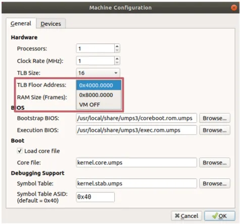
The TLB Floor Address is a new parameter implemented in µMPS3, responsible for indicating which addresses from a certain value on are con-sidered logical, and therefore subject to address translation—the process of mapping logical addresses to physical ones. By doing this, the processes per-ceive more physical memory than the one actually available, recreating an abstract view of the address space.
This parameter can be chosen directly from the configuration dialog in the emulator front-end, as Figure 2.4 shows:
Figure 2.4: TLB Floor Address
The last option, VM OFF, is internally declared as 0xFFFF.FFFF: since it is not possible to access to an address above this value, the entire physical memory is necessarily below it, and therefore, an address translation could never happen.
2.3 Previous Implementation 13
2.3
Previous Implementation
The physical address space was substantially equal to the new one, except for the moving and renaming of the new “BIOS Data Page”.
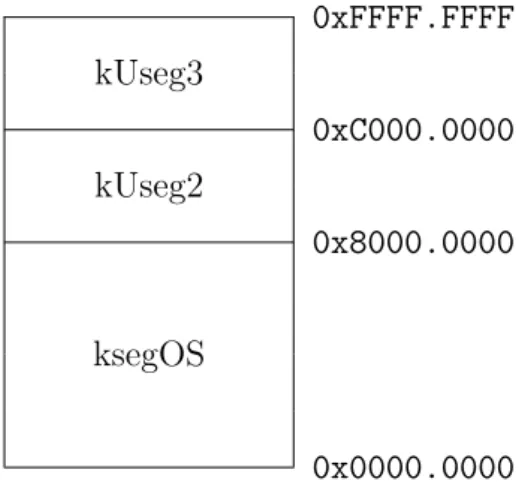
On the other hand, the virtual memory was implemented through a segmented-paged scheme. Hence, a new abstraction layer was laid on the whole physical memory structure, subdividing it into three big segments [Figure 2.5]:
• ksegOS, from address 0x0000.0000 to 0x8000.0000: a 2GB segment reserved for the text, data and stacks of the OS, along with all the struc-tures sitting in the BIOS reserved space up to address 0x2000.0000;
• kUseg2, from address 0x8000.0000 to 0xC000.0000: a 1GB logical ad-dress space reserved for the text, data and stacks of the user processes;
• kUseg3, from address 0xC000.0000 to 0xFFFF.FFFF: another 1GB log-ical address space reserved for the use of user-mode processes.
0xFFFF.FFFF kUseg3 0xC000.0000 kUseg2 0x8000.0000 ksegOS 0x0000.0000
Figure 2.5: Old Virtual Memory Structure
As for the new version, all the addresses below 0x8000.0000 were reserved to kernel-mode access only.
14 2. Memory Management
Whether this subdivision was active or not was controlled by the VM bit. With the VM bit off, no particular actions were required when access-ing the memory space. Instead, when the VM bit was on, all the address above 0x2000.0000 were considered logical and sent to the MMU for address translation.
The VM bit was originally introduced in the first version of µMPS, with the intent of simplifying the complex virtual memory management system of the MIPS R3000 microprocessor. The activation and deactivation of it was accomplished through the system control coprocessor CP0.
It provides a 32-bit Status register that controls various aspects of the emulator, described in details in [7]. Along with the current options set of the register, it also provided the possibility, by using bitwise operations, to control the status of the VM bit: it was implemented as a 3-slot deep bit stack (current, previous, previous of previous) which was pushed or popped depending on whether an exception was raised or an interrupted execution stream was restarted [section 3.2 and subsection 6.2.1 of [8]].
The virtual address translation process went through a significant change in this major revision: the formal segment table [subsections 4.3.1 of [8]], introduced in the first implementation of µMPS, have been removed. Conse-quently, only TLB table formats remain implemented, resulting in a simpler procedure for the users [7].
During the implementation of a new feature of the emulator, the VM bit has been completely removed too.
2.4
VM Bit Removal
The VM bit removal is one of the main features of µMPS3: the push/pop system has been removed, and the three bits previously reserved for it are now completely ignored. Hence, from now on, the virtual memory is conceptually always on. This means that all the addresses above a certain value are considered logical and therefore, subject to address translation. This specific
2.4 VM Bit Removal 15
value, while in previous version was fixed at 0x2000.0000, is now contained in a variable called TLB Floor Address [subsection 2.2.1].
The TLB Floor Address value is stored in the Bus Register Area, thereby adding one word to the ten word area of the previous version [Table 2.1]:
Physical Address Field Name
0x1000.0028 TLB Floor Address
0x1000.0024 Time Scale
0x1000.0020 Interval Timer
0x1000.001C Time of Day Clock - Low 0x1000.0018 Time of Day Clock - High 0x1000.0014 Installed Bootstrap BIOS Services Size 0x1000.0010 Bootstrap BIOS Services Base Physical Address 0x1000.000C Installed Exec. BIOS Services Size
0x1000.0008 Exec. BIOS Services Base Physical Address 0x1000.0004 Installed RAM Size
0x1000.0000 RAM Base Physical Address
Table 2.1: Bus Register Area
One of the consequences of the implementation of this value at the end of the Bus Register Area has been the shifting up of one word of the two successive areas, Installed Devices Bit Map and Interrupting Devices Bit Map.
The TLB Floor Address field cannot be changed while the emulator is running, but only from the front-end dialog.
After saving the machine configuration from the GUI, the TLB Floor Ad-dress value will be placed inside the JSON-based configuration file, described in detail in subsection 4.2.1 of Jonjic’s Thesis [11].
16 2. Memory Management
An example of the final portion of a simple machine configuration is represented in Listing 2.1: 19 ... 20 } , 21 " tlb - floor - a d d r e s s ": "0 x 4 0 0 0 0 0 0 0 " , 22 " tlb - s i z e ": 16 23 }
Listing 2.1: TLB Floor Address
On line 21 is shown the value saved as string: this decision was taken to preserve the human-readable notational convention.
Chapter 3
Exception Handling
Exceptions are particular events interrupting the normal execution flow of a machine. Different categories of them exist, each one raised in corre-spondence of a certain occurrence. Depending on their type, the exceptions require to be handled in a distinct special way rather than the ordinary workflow of the system.
From a hardware perspective, µMPS3 supports two major types of ex-ceptions: TLB-Refill exceptions, and all the other ones. However, from the software viewpoint, thanks to a high-level abstraction, they could be subdi-vided in four different categories:
• Program Traps: these exceptions are usually raised when the user-defined workflow commits an error, like: Address Error, Bus Error, Reserved Instruction, Coprocessor Unusable or Arithmetic Overflow ;
• System Calls and Breakpoints: these two occur whenever a process requests an OS service through the SYSCALL or the BREAK instruction;
• Interrupts: I/O devices that complete their previously started opera-tion must notify it to the processor, and they do it by raising this type of exception. There are a total of 8 interrupt lines: 3 of them are ded-icated to internally generated interrupts, while the other 5 to external devices. Each of these last five ones support up to 8 devices attached
18 3. Exception Handling
to them;
• TLB-related exceptions: exceptions linked to the Translation Lookaside Buffer : TLB-Modification, TLB-Invalid and TLB-Refill.
Going more in details on Program Traps, from [7]:
• Address Error is raised when:
– a load/store/instruction fetch of a word is not aligned with a word boundary;
– a load/store of a half-word is not aligned with a halfword boundary;
– a user-mode access is made to an address below 0x8000.0000; • Bus Error is raised whenever an access is attempted on a
non-existent physical memory location or when an attempt is made to write onto the BIOS device;
• Reserved Instruction is raised whenever an instruction is ill-formed, not recognizable, or it is privileged and executed while in user-mode;
• Coprocessor Unusable is raised whenever an instruction re-quiring the use of (or access to) an uninstalled or currently unavailable coprocessor is executed;
• Arithmetic Overflow is raised whenever an ADD or SUB in-struction execution results in a two’s complement overflow;
The TLB (Translation Lookaside Buffer) is a component of the Virtual Memory management system whose functioning has not changed. However, its exception handling did, and, therefore, a little background is needed to explain the modifications made. From [7]:
The TLB is a theoretical associative cache, that can hold from 4 to 64 TLB entries. Each TLB entry describes the mapping be-tween one ASID-logical page number pairing and a physical frame
3.1 Processor Actions on Exception 19
number/location in RAM. By utilizing a cache of recently used TLB entries, the virtual address translation mechanism of µMPS3 can avoid making multiple memory accesses for each translation. Since it is impossible to realistically emulate this kind of imple-mentation, the TLB is therefore linearly searched.
Hence, regarding TLB-related exceptions, from [7]:
• TLB-Modification is raised when on a write request a
“match-ing” entry is found, the entry is marked valid, but not dirty/writable;
• TLB-Invalid is raised whenever a “matching” entry is found but the entry is marked invalid;
• TLB-Refill is raised when no “matching” entry is found.
3.1
Processor Actions on Exception
When an exception is raised, the processor state (what it was “doing”) must be saved in order to restart from that point after the exception has been handled. Before doing this, the processor has to take a number of atomic steps (non-interruptible, without any visible intermediary state), which are possible by:
• disabling all interrupts, to make sure nothing could disturb the entire handling process;
• activating the kernel-mode, since the access to the memory area in-tended for saving (and retrieving) the processor state is denied to user-mode processes.
Other essential processor actions are taken, some of them based on the type of the exception. They remain unchanged from µMPS2, and explained in detail in [7].
20 3. Exception Handling
3.2
BIOS Data Page
0x1000.0000 0x0FFF.FA00 16× Pass Up Vectors Area 0x0FFF.F900 0x0FFF.F8C0 16× Processors States Area 0x0FFF.F000 (a) Overview 0x0FFF.F910 General Exception Stack Pointer 0x0FFF.F90C General Exception Handler Address 0x0FFF.F908 TLB-Refill Stack Pointer 0x0FFF.F904 TLB-Refill Handler Address 0x0FFF.F900
(b) Pass Up Vector Area
Figure 3.1: BIOS Data Page
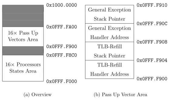
The BIOS Data Page is the new 4KB area of µMPS3 reserved for the exception handling. As Figure 3.1a shows, it contains:
• a Processors States Area, from address 0x0FFF.F000 to 0x0FFF.F8C0: a 35 (state size) × 16 (maximum number of active CPUs) word area dedicated to store the state loaded onto one processor at the moment an exception occurred. Since µMPS2 implemented the multiprocessor support, one area for each active CPU is needed. The area of processor 0 is at address 0x0FFF.F000, the one of processor 1 at 0x0FFF.F08C (+35 words) and so on;
• a Pass Up Vectors Area, from address 0x0FFF.F900 to 0x0FFF.FA00: a 4 × 16 word area containing, for each active CPU:
– the address of its TLB-Refill handler, to which the workflow will jump after saving the processor state;
3.3 Previous Implementation 21
– the stack pointer of the TLB-Refill handler; – the address of its general exceptions handler ; – the stack pointer of the general exceptions handler;
Figure 3.1b shows this four-word area for the first processor. As for the previously reserved space, these areas are ordered one after the other, from low to high processors numbers. The processor 1 Pass Up Vector will be at address 0x0FFF.F910, the processor 2 Pass Up Vector at 0x0FFF.F920 (+4 words) and so on.
This area is used as an interface between the two kernel handlers and the BIOS Exception Handlers.
3.2.1
BIOS Exception Handlers
The BIOS Exception Handlers are routines whose job is to prepare the environment on which the kernel exception handlers will work. This means that, after an exception has been raised, before the user-defined functions take place, a series of different actions are made by the BIOS, depending on the type of the exception.
Apart from some error checking, their essential task is to store off the processor state in the exact moment the execution flow has been interrupted in a “safe place” located in memory (the Processors States Area). Further-more, the Program Counter will jump to the address of the appropriate kernel handler, thus ending the BIOS handlers job.
This “passing” set of instructions was internally distinguished into two main categories of events: TLB-Refill exceptions and all the other ones. The entire new exception handling system of µMPS3 is based on this distinction.
3.3
Previous Implementation
The exception handling of µMPS2 was managed by distinguishing them by their type: Program Traps, System Calls and Breakpoints, Interrupts and
22 3. Exception Handling
TLB-related exceptions.
Since this subdivision existed, four different areas were needed to save the processor state (called old areas). The functions to subsequently call were treated as new states to load onto the processor, hence, four other areas were needed (called new areas), which contained the addresses of the exception handlers.
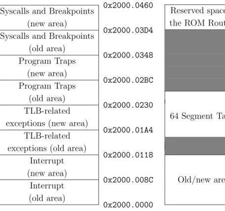
These four pair of areas, each one linked to its specific type of exception, were stored in a 35 (state size)× 8 word area [Figure 3.2a] at the beginning of the so-called ROM Reserved Frame [Figure 3.2].
3.3.1
ROM Reserved Frame
0x2000.0460 Syscalls and Breakpoints
(new area)
0x2000.03D4 Syscalls and Breakpoints
(old area) 0x2000.0348 Program Traps (new area) 0x2000.02BC Program Traps (old area) 0x2000.0230 TLB-related
exceptions (new area)
0x2000.01A4 TLB-related
exceptions (old area)
0x2000.0118 Interrupt (new area) 0x2000.008C Interrupt (old area) 0x2000.0000
(a) Old and New State Areas
0x2000.1000 Reserved space for
the ROM Routines
0x2000.0FF0 0x2000.0800 64 Segment Tables 0x2000.0500 0x2000.0460 Old/new areas 0x2000.0000 (b) Overview
3.4 Differences from µMPS2 23
The ROM Reserved Frame was a 4KB (frame size) area at the beginning of the installed RAM. It was used, apart from storing the old/new states of the processor, also to contain other structures, as Figure 3.2b shows:
• a Segment Table, from address 0x2000.0500 to 0x2000.0800: a 64 (number of maximum concurrent processes) × 3 (number of µMPS2 segments) word area containing page table pointers [subsection 4.3.1 of [8]];
• a Reserved Space, from address 0x2000.0FF0 to 0x2000.1000, dedi-cated to storing pointers to each old/new areas of the processors needed for the execution of the ROM (now called BIOS) exception handlers.
3.4
Differences from µMPS2
In addition to the two atomic actions described in section 3.1, another step to disable the virtual memory was taken in µMPS2, since the area reserved for the processor states was above the address 0x2000.0000 [Figure 3.2]. With the virtual memory bit enabled, those addresses were considered logical, leading to possible raises of TLB-management exceptions, which would have meant entering in an infinite loop. However, as explained in section 2.4, this complexity has been completely removed along with the virtual memory disabling process performed by the processor.
The 192 word Segment Table area [Figure 3.2b] has been eliminated too in µMPS3, since it is no longer used in the new address translation process. Since all the internal exception handling was already dealt upon the sep-aration of the “TLB-Refill/all the others” exceptions by the Execution BIOS Services, the current implementation elucidates this split to the users, who previously had to distinguish between four categories of events. While TLB-Refill events were previously handled by the BIOS, it is now a kernel respon-sibility; for this reason, two exception types, raised only during TLB-Refill events, have been removed.
24 3. Exception Handling
In addition, the kernel handlers to which the control is passed are no more treated as new states to load onto the processor, but just as functions to which let the Program Counter jump to. This means that the four “new” processor state areas are no longer needed too, and has been reduced to only two one-word areas.
Two more one-word areas are needed for the two stack pointers of the handlers, something analogue to what was previously stored at the end of the first frame of RAM.
The ROM Reserved Frame, previously sat in the first frame of RAM, has been moved to the last frame of memory below the address 0x1000.0000 (where the Bus Register Area starts) and renamed into BIOS Data Page [Figure 3.1].
Finally, the BIOS exception handlers have been updated as well, simpli-fying the code which sometimes was redundant and in order to comply with the changes of the exception handling system. They have also been renamed from “ROM exception handlers” for a better overall analogy, since they be-long to a reprogrammable BIOS and do not reside in a Read-Only Memory space.
How µMPS3 knows where to find the right area to save the state of each processor and where to retrieve the handlers is described along with the updated multiprocessor support in chapter 4.
Chapter 4
Multiprocessor Support
The first major revision, µMPS2, has implemented the multiprocessor support: the emulator is currently capable of supporting up to 16 simulta-neously active CPUs. Their functioning has not been changed in this new version of the emulator, described in detail at chapter 7 of [8]. However, it is important to understand how their initialization has been modified in order to comply with the new exception handling [chapter 3].
4.1
Processors Initialization
As subsection 7.2.2 of [8] explains, each processor has a private set of five Processor Interface Registers [Table 4.1], and each one sees only its own pri-vate instance. While the first three fields have not changed in their working, the other two have.
Address Register Type
0x1000.0400 Inbox Read/Write 0x1000.0404 Outbox Write Only
0x1000.0408 TPR Read/Write
0x1000.040c BIOS Reserved 1 Read/Write 0x1000.0410 BIOS Reserved 2 Read/Write
Table 4.1: Processor Interface Registers
26 4. Multiprocessor Support
4.1.1
Processor 0
The first things loaded right after the machine has been turned on (or restarted), are the Bootstrap BIOS Services [7]. They are responsible for setting up the correct handling areas [section 3.2] for the default processor, the first one. BIOS Reserved 1 and BIOS Reserved 2 are used for this purpose.
In µMPS2, for the first processor, the BIOS Reserved 1 register was set, by the Bootstrap BIOS Services, to point the beginning of the Old/New State Area [Figure 3.2a], at address 0x2000.0000. The BIOS Reserved 2 register was set to point the reserved space at the end of the first frame of RAM, at address 0x2000.1000.
In µMPS3, at boot/reset time, the Bootstrap BIOS Services set up the BIOS Reserved 1 register to point the bottom of the BIOS Data Page [Fig-ure 3.1], at address 0x0FFF.F000, where the reserved exception state space for processor 0 starts. On the other hand, BIOS Reserved 2 now points to the Pass Up Vector of processor 0, at address 0x0FFF.F900.
After that, the Bootstrap BIOS Services load the OS code.
4.1.2
Processors 1-15
How all the other processors were previously initialized is described in subsection 7.1.2 of [8].
To sum up, the libumps library provides a BIOS service designed to sim-plify the initialization of the processors. Libumps is a C library supplied with µMPS installation to provide access to CP0 instructions, the CP0 registers, and the extended BIOS-based services/instructions avoiding to program in MIPS assembler.
This specific BIOS service is called initCPU, and the original syntax was:
void INITCPU (uint32_t cpuid,
state_t *start_state, state_t *state_areas);
4.1 Processors Initialization 27
In µMPS2, initCPU initiated the processor specified by cpuid, loading the processor state from the supplied start state parameter onto it. The address of BIOS Reserved 2 was calculated by multiplying the processor number × the size of the reserved space the BIOS needed for the handlers of each CPU (32 bytes). Since a separate space was needed for Old/New Processor State Areas too, the third parameter, state areas, was used to indicate the address for BIOS Reserved 1 [subsection 7.5.2 of [8]].
In µMPS3, the implementation of initCPU keeps only the first two pa-rameters, calculating internally the correct areas where to save the processor state without needing the user:
void INITCPU (uint32_t cpuid,
state_t *start_state);
The start state parameter is used to initialize the cpuid processor as in µMPS2. The cpuid parameter is now multiplied× the size of a processor state (35 words) to get an offset to be summed to the bottom of the BIOS Data Page [section 3.2]: this value indicates the address of the processor exception state area, the same one BIOS Reserved 1 has to point to (e.g. 0x0FFF.F08C for processor 1, 0x0FFF.F118 for processor 2 and so on). The other Processor Interface Register is set up similarly, multiplying the pro-cessor ID × the size of the Pass Up Vector area (4 words): this value is the offset from address 0x0FFF.F900 to which BIOS Reserved 2 has to point to (e.g. 0x0FFF.F910 for processor 1, 0x0FFF.F920 for processor 2 and so on). Now, the BIOS routines only have to use BIOS Reserved 1 and BIOS Reserved 2 of a processor to retrieve the correct exception state area and the required Pass Up Vector.
Chapter 5
Device Interfaces
Since its first implementation, besides the MIPS R3000 microprocessor, µMPS has always been able to emulate five different device categories: disks, tapes, network adapters, printers and terminals. Furthermore, it can support up to eight instances of each device type.
This chapter will provide the reasons why, along with this major revision, one of the devices has been replaced with a new one.
As for the functioning and implementation of the remaining devices, the reader may refer to the manual [7].
5.1
Tape drives
MPS has been conceived and developed in the late ’90s, and many updates and improvements have followed to make it as it is nowadays.
It is simple to imagine how much can technology achieve in over 20 years, and µMPS devices are not exempt from this process. Therefore, it may not be a surprise how hard disk drives are, nowadays, less and less used, outclassed by new solid-state drives, despite their still being common knowledge.
Network adapters are still present and properly taught in every IT class, although changed in their appearance, from physical to wireless, and certainly much faster, but the speed of the devices is not what concerns µMPS, on the
30 5. Device Interfaces
contrary, the goal is to teach their functioning.
Whereas there is not a real reason to think about the replacement of printers and terminals, there is one last device category about which the same cannot be said: tape drives.
In modern ages, tape drives are only studied in History of computer science classes, and are no longer found in real implementations if not in rare cases. As a result, only older users still know what tapes are, their functioning and their use, therefore new generations are slowly losing consciousness of what they are or, admittedly, never heard of them.
Given all of this, it would have been a misstep not to use them, as when µMPS2 was released in 2011, technology was going through a transaction, and those who were still students knew of them. However, after almost ten years, the situation has changed, and tapes are no longer used in common systems.
Tapes, in µMPS2, were implemented as read-only DMA (Direct Memory Access) devices, capable of transferring 4KB blocks of data per time, concur-rently for each installed device of this category. Internally, they were divided into equal sized frames of 4KB each, through the use of four marked codes: EOT (end-of-tape), EOF (end-of-file), EOB (end-of-block), TS (tape-start), to scan the reading process and simulating the movement of a head on a tape. In order to let the students work with a storage device slower than disks, but still familiar to them, µMPS3 had to completely remove tapes to imple-ment a new category of devices: flash drive devices.
5.2
Flash Drives
A flash drive device, also know as “USB sticks” or “SD cards”, is a stor-age device using flash memory, which is a solid-state memory, therefore not implemented through physical disks or tapes, that can be electrically erased and reprogrammed. Unlike disks or tapes, a “seek” operation—that moves a head assembly over a physical surface—is not needed before reading from
5.2 Flash Drives 31
or writing to a specific block or sector.
In order to reproduce the same experience in µMPS3, the easiest way is to take a similar implemented device, the disk, remove the “seek” operation from it and simplify the coordinates system (cylinder, head, sector) to a single contiguous block addressable space [0...MAXBLOCKS-1].
Hence, a flash drive device is a read/writable DMA device, divided into equal-sized frames of the same dimension of µMPS3 framesize, 4KB, each one accessible via specific block number.
µMPS3 uses a 3 byte (24 bit) address space for flash device, consequently, each device in this category can have up to 224(0xFFFFFF) blocks of memory,
which is equivalent to a maximum size of 64GB.
As already said, a flash drive device is usually slower than a disk device. However, the umps3-mkdev utility, which comes with µMPS3 installation and allows the user to create a disk or a flash device image, accepts a speed argument for both of them: “seek time” for disks and “write time” for flash devices. Therefore, this does not prevent anyone to voluntarily create a flash device significantly faster than a disk device. Theoretically, thanks to the implementation of this device, it would represent an SSD in every aspects.
The speed-related argument is optional, and, if not given, umps3-mkdev will use default values:
#define DFLSEEKTIME 100
#define DFLWTIME DFLSEEKTIME * 10
Like intuitively understandable from the constants name, the first one is for the default disks seek time, while the latter is for the default flash devices write time. This means that, if not voluntarily indicated by the user who creates a device, the write time will always be ten times slower than the seek time for a default disk device.
The read time for a flash device cannot be directly defined, but it will be calculated ad-hoc when needed by multiplying the device set write time by:
32 5. Device Interfaces
This way, the read speed will always be 25% faster than write speed, since it will take 3/4 of time, almost as in real-world implementation.
5.2.1
Creation
As umps2-mkdev allowed to create image files of tape devices, umps3-mkdev permits to create flash device ones via the following syntax (also visible by running the utility with no arguments):
$ umps3-mkdev -f <flashfile>.umps <file> [blocks [wt]]
where:
• -f : specify the creation of a flash device image instead of a disk one (-d);
• <flashfile> : the name of the flash device image file that will be created;
• <file> : file to be written into the new flash device image; • blocks : number of blocks [1...0xFFFFFF] (default = 512);
• wt : average write time (in microseconds) [1...100000] (default = 1000); It is also possible to create an empty flash device image file by passing “/dev/null” as <file> argument.
Going more in detail, after correctly running the previous command, the utility will decode command-line arguments, if existing.
Then, it will attempt to open the flash device image file in write-mode. If the operation is successful, a FLASHFILEID (0x0153504D) will be written into the first word of memory of the file. This file recognition tag is used to distinguish this type of file from all the other types of files generated or recognized by µMPS3.
Number of blocks and write speed are also subsequently written, which, along with the FLASHFILEID, compose the header of the flash device. These
5.2 Flash Drives 33
three parameters will be needed by µMPS3, when interacting with the device, to correctly simulate it.
Lastly, after opening it in read-mode, the existing file will be written inside the image file block-by-block.
Once the end-of-file indicator is reached, the remaining space will be filled with empty blocks. In case no errors occurred, the flash device image file will be successfully created.
5.2.2
Usage
The use of a flash device, in µMPS3, is not significantly different from the use of any other device. As reported in the manual µMPS3 Principles of Operation [7]:
Every single device is operated by a controller. Controllers ex-change information with the processor via device registers; special memory locations. A device register is a consecutive 4-word block of memory. By writing and reading specific fields in a given vice register, the processor may both issue commands and test de-vice status and responses. µMPS3 implements the full-handshake interrupt-driven protocol. Specifically:
1. Communication with device i is initiated by the writing of a command code into device i ’s device register.
2. Device i ’s controller responds by both starting the indicated operation and setting a status field in i ’s device register.
3. When the indicated operation completes, device i ’s con-troller will again set some fields in i ’s device register; in-cluding the status field. Furthermore, device i ’s controller will generate an interrupt exception by asserting the ap-propriate interrupt line. The generated interrupt exception informs the processor that the requested operation has con-cluded and that the device requires its attention.
34 5. Device Interfaces
4. The interrupt is acknowledged by writing the acknowledge command code in device i ’s device register.
5. Device i ’s controller will de-assert the interrupt line and the protocol can restart. For performance purposes, writing a new command after the interrupt is generated will both acknowledge the interrupt and start a new operation imme-diately.
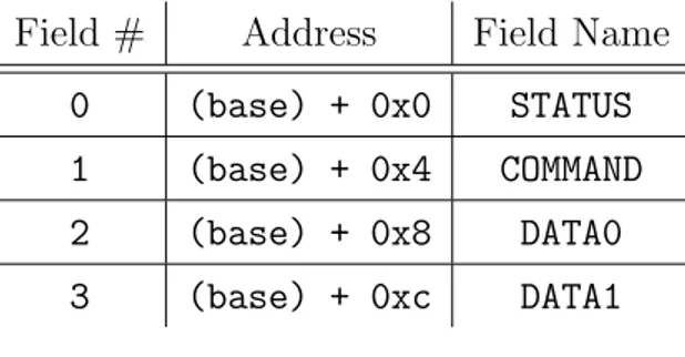
The flash device registers are located in low-memory, starting at 0x100000D4 for flash0 up to 0x10000144 for flash7. Each register consists of 4 fields:
Field # Address Field Name
0 (base) + 0x0 STATUS 1 (base) + 0x4 COMMAND 2 (base) + 0x8 DATA0 3 (base) + 0xc DATA1
Table 5.1: Device Register Layout
The STATUS field of a flash device register is read-only and will contain one of the following status codes:
Code Status Possible Reason for Code
0 Device Not Installed Device not installed 1 Device Ready Device waiting for a command 2 Illegal Operation Device presented unknown command 3 Device Busy Device executing a command 4 Read Error Illegal parameter/hardware failure 5 Write Error Illegal parameter/hardware failure 6 DMA Transfer Error Illegal physical address/hardware failure
5.2 Flash Drives 35
From [7]:
Status codes 1, 2, and 4-6 are completion codes. An illegal pa-rameter may be an out of bounds value (e.g. a block number outside of [0..MAXBLOCK-1]), or a non-existent physical address for DMA transfers.
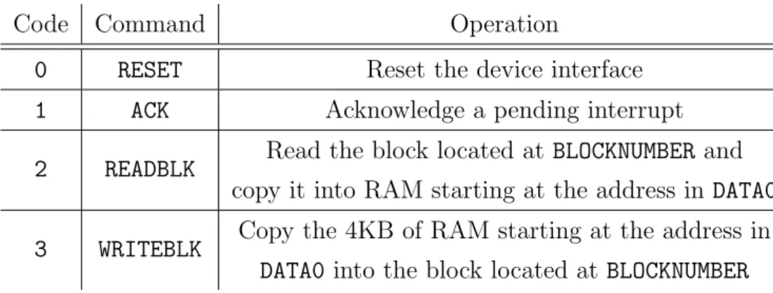
The COMMAND field of a flash device register is read/writable and is used to issue commands to the device:
Code Command Operation
0 RESET Reset the device interface 1 ACK Acknowledge a pending interrupt
2 READBLK Read the block located at BLOCKNUMBER and copy it into RAM starting at the address in DATA0
3 WRITEBLK Copy the 4KB of RAM starting at the address in DATA0 into the block located at BLOCKNUMBER
Table 5.3: Flash Device Command Codes
The format of the COMMAND field is illustrated in Figure 5.1:
31 8 7 0
BLOCKNUMBER CODE
Figure 5.1: Flash Device COMMAND Field
An operation on a flash device is started by loading the appro-priate value into the COMMAND field. For the duration of the op-eration, the device status is “Device Busy”. Upon completion of the operation, an interrupt is raised and an appropriate status code is set: “Device Ready” for successful completion or one of the error codes. The interrupt is then acknowledged by issuing an ACK or RESET command.
36 5. Device Interfaces
The DATA0 field of a flash device register is read/writable and is used to specify the starting physical address for a read or write DMA operation. Since memory is addressed from low addresses to high ones, this address is the lowest word-aligned physical ad-dress of the 4KB block about to be transferred.
The DATA1 field of each device register is read-only and describes the physical characteristics of the device geometry [Figure 5.2].
31 24 23 0
NUMBER OF BLOCKS
Chapter 6
Project Structure Update
Many years have passed since the initial release of µMPS, and some as-pects of it have become inevitably outdated. Along with all the changes described in the previous chapters, the software went through a refresh at-tempt which tried to update it to current standards and common procedures. Each modification made will be described in this chapter, together with the reasons to implement them, crucial to the aim of using the software for many years to come.
6.1
Build System
Developing software to use as a pedagogical tool requires being aware of some aspects. It will need to be spread among the students, hopefully, one copy per person. Schools and Universities usually dispose of computer labs, but the possibility of working on it from home is always appreciated. This will be particularly convenient when the software concerned will be used as a study aid in a computer class—and it is well-known that programmers work at any time of day (or night).
Given this premise, the tool should be installable on the students’ personal computers, and one problem that does not usually show up on laboratories machines is the system diversity. The software developers could surely give
38 6. Project Structure Update
requirements and instructions on how to install it on different computers de-pending, for example, on the hardware, but when it comes to larger projects with lots of dependencies and steps to be able to run it, it is always prefer-able to use an automatic process. µMPS represents a classical example of this kind of big project, with a not so simple building and installing procedure.
In the late 1990s, when its development started, there was principally one solution: the GNU Autotools [9]. GNU Autotools were, de facto, the reference toolchain of programs helping developers to distribute their software fulfilling the users of complex procedures.
These tools are known as the Build System of a project, and they allow to define a series of instructions spread over files within the source code direc-tory. The initial configuration phase will follow these instructions, generating a specific file depending on the operating environment on which it will run. From the programming view, they avoid distributing different procedures or source code for every system implementation, because, after setting every-thing up as needed, they will take care of it. From the user perspective, after obtaining the source code, the building phase will be possible in just a couple of predefined steps. It is also important to note that the building tools of a project are the first thing a user needs to interface to. In addition, for those not skilled students, the installation of the software could be their first-ever experience with them.
The Autools are still a very popular choice during the design stage of a software, but, with time, many other valid alternatives arose. For this reason, µMPS3 tries to simplify its installation phase by moving to a new building suite, which has been one of the most popular choices over the last few years: CMake.
6.1.1
CMake
Migrating µMPS3 to CMake has brought some benefits. First of all, whoever experienced the installation of the previous version can now notice a significant increase speed of this phase. CMake has a faster building time
6.2 Graphical User Interface 39
due to the avoidance of numerous system checks that the other building tools do. More verifications mean more reliability, but most of Autotools checks were on system features which have been integrated by default in every distribution or in the Linux kernel [10] itself, making them useless.
CMake is also far less wordy, requiring a minor number of files in the source code directory and far fewer lines of code. Hence, from a programming perspective, the whole codebase is now “lighter”.
Since a lot of relatively recent projects are based on this building tool, it should be easier to learn too, and this could encourage development contri-butions by novice programmers.
Lastly, µMPS2 have gone through a graphical user interface upgrade, discarding the original one and re-designing everything in Qt. This important process was necessary to keep up with current standards, but, unfortunately, the Autotools don’t combine well with the new GUI of choice. It is surely possible to make them work together, as it has been until now, but this requires a heavy configuration, not recommended most of the time given the alternatives. µMPS3 could have just used the already implemented Autotools structure, but another update, almost completely incompatible with the old building tools, had to be done: the transition from Qt4 to Qt5.
6.2
Graphical User Interface
The µMPS front-end is one of its most important aspects, since it is the first thing a student sees after launching it. Being a pedagogical tool, one would expect it to be used by any level of experience in the area, hence, it should be the most intuitive possible. Nevertheless, this must not prevent the possibility to access every advanced feature directly from the GUI. Jonjic has perfectly succeeded in this goal implementing the current one, described in detail in the 3rd chapter of his thesis [11], and this third version of the software brings only an update of the one built by him.
40 6. Project Structure Update
6.2.1
Qt5
Qt is a toolkit for creating graphical user interfaces, and the currently available version is the fifth one. It has been originally released just a couple of years later than µMPS2, which is built upon the fourth one. The time to migrate to this new version has certainly come, and thanks to their high compatibility all the process went significantly smooth. The rule applied during the transition was the classical “if it is not broke, do not fix it”, maintaining the same interface already implemented and upgrading just the essential.
From the user perspective view, µMPS3 tries to make a couple of aspects even more intuitive than before, thanks to the students feedback acquired during the past 10 years.
6.2.2
Logo and Icon Theme
The very first visible characteristic is the new icon theme. The decision to update has been made because the old ones were not much intuitive for some common actions, like the two dedicated for switching on and off the machine, compared along with the new ones in Table 6.1.
Old New Power ON
Power OFF
Table 6.1: Start and Halt icons
These two icons were available as shortcuts in the top bar of the GUI. Since they were alternating each other (the one for turning on the machine was disabled once pressed, the other one was available only with the machine powered on), they have been merged in a single shortcut displaying only the action currently available.
6.2 Graphical User Interface 41
Similarly, the same procedure has been done for the two “start” and “stop” icons.
Another reason for changing the icon theme was the replacement of tapes with flash devices, whose icon was not available in the previous one.
All the new images are in the SVG format, which is an advantage in years like these, where the resolution and DPI of computers screens are increasing quickly. With the drop of all the other PNG icons, these new ones could be easily scaled up in the future if needed, without losing quality.
The chosen theme is Papirus by Papirus Development Team [12], licensed under GPL-3.0 [13]. Following the license terms, the one of µMPS3 has been upgraded from the original GPL-2.0 to the new GPL-3.0 too.
All the other non-available icons were obtained from similar existing ones with the Inkscape [14] software, following the same graphic style for the best eye pleasure possible. With the same procedure, the new µMPS logo has been created [Figure 6.1]. The font used for the central letter “µ” is Ubuntu Monospace from Canonical [15].
µ
Figure 6.1: µMPS3 Logo
6.2.3
Other Improvements
There have been other small changes in the emulator front-end, intending to improve the user experience as much as possible.
The “Edit configuration” menu entry has been moved from the “Machine” menu voice to the “Simulator” one, in a more intuitive position [Figure 6.2].
42 6. Project Structure Update
(a) µMPS2
(b) µMPS3
Figure 6.2: Edit Configuration Menu Entry
A “Clear recent ” option has been added, an underestimated, yet still useful, function offering the possibility to remove all the used machine con-figurations from the “Recent menu” [Figure 6.3]. Previously, the only way to do it was by manually editing ∼/.config/umps3/umps.conf, not a very practical method to clear the emulator overview.
6.2 Graphical User Interface 43
The “Reset ” shortcut has been made available in the processor view as well. This is a convenient option when debugging using only the keyboard, thus allowing the restart of the machine without the need to move between front-end windows [Figure 6.4].
Figure 6.4: Reset Shortcut
The RAMTOP value of the machine is now available from the configuration overview [Figure 6.5], increasing the transparency for the user on how the physical memory of µMPS works [section 2.1].
Chapter 7
Conclusions
The µMPS project was created almost twenty years ago as a didactic sup-port for operating system courses. Over time, many instructors have chosen it as an aid in their classes, allowing it to reach its initial goal. However, from the day the last version has been released, educational and technolog-ical standards have changed in many ways, and the consideration of it has been dropping to these days. A refresh of the emulator was needed, in order to renovate the outdated features and reintroduce it to new OS instructors. Thus, µMPS3 has been designed and implemented, and describing how this update differs from the previous version is the work of this thesis.
The most changed aspect is, probably, the whole memory system, which has been simplified compared to the original design, aligned to modern man-agement techniques, and, ironically, unintentionally brought back to the orig-inal MIPS architecture in various facets.
The internal exception handling system (BIOS routines) has been com-pletely redesigned, facilitating its operation and requiring less work from the students. By moving some responsibilities from the kernel to the BIOS, the users kernel designing job is simpler and less sophisticated. This new implementation led also to the modification of the processors initialization process.
From the set of five previously supported devices, the tape is the one
46 7. Conclusions
which suffered the most the passage of time. Very few µMPS users from the current generation of students are aware of how it works or what it even is. Current hardware like USB sticks or SD cards is surely more appropriate for educational purpose, since a familiar match of what one is working on helps to understand better. For these reasons, the new class of flash devices has been introduced, filling the need for substituting another outdated view of the project.
Last but not least, the project building process had to be simplified. It was probably the very first (underestimated) obstacle that students encoun-tered while trying to install µMPS, and it was based on the GNU Autotools. The migration to a new, current, building tool like CMake made the whole procedure more linear and pretty straightforward. The graphical user inter-face has not been revolutionized, but it has been updated anyway from Qt4 to Qt5 with the addition of a few adjustments.
With this second major revision, the µMPS project is once again in line with how a proper current operating systems study aid should be structured.
7.1
Future Work
µMPS is one of those projects where the work to be done is potentially endless. Uncountable changes are possible, both big or small, in order to enhance the quality of the software. The most important, obvious or already planned proposal, will be explained in this final part of the thesis, but it is important to remember that no matter how many examples will be given, it will always be a non-exhaustive list.
7.1.1
Software Packaging
Once a software has been released, it has to be distributed to future users. µMPS is an open-source project, and its code will be always available in public Git [16] repositories like GitHub [17]. This allows it to be always built from source and installed in almost every system. However, it is always
7.1 Future Work 47
preferable to install software from official repositories when available, since it permits an integrated tracking of installed files and an automatic updates system. Therefore, the first task after µMPS3 release is packaging it for Linux distros, to simplify even more its installation process, which will also permit a solid future updates distribution.
Debian [18] is the main distribution for which the software must be pack-aged, since along with all its derivates it covers the majority of the most popular distros used. The guidelines of its packaging process are the most stringent, but once the package is complete the porting to other derivates repositories should be straightforward.
The second major distribution that is taking hold in these days is Arch Linux [19], along with a long list of derivates as well. The packaging process for this distribution is a lot more simpler than for Debian, and users-produced packages can be uploaded in the dedicated repository at any time in a few steps. The second version of the software, µMPS2, has been available in the AUR (Arch User Repository) for over a year.
There are obviously a large number of other Linux distributions not based on Debian or Arch, for which the two packaging processes listed before are, then, useless. Satisfying all the possible Linux “flavours” is an almost infinite work, and it is hoped that others will contribute to this cause by creating the package for the distribution they use.
Other possible solutions are distro agnostic packages, like Flatpak [20], AppImage [21], and Snapcraft [22]. They provide a way to distribute software that could run on every system regardless of the distribution used.
7.1.2
Persistent Debugging Settings
Thanks to the advanced debugging support, µMPS is unique in its kind. All the related features allow a high-level dismantling of the machine work-flow, that enables the user to exactly understand what the emulator is doing or where the code is failing. Sadly, the settings environment related to a machine that can be created at runtime cannot be saved on the disk, and it