INTERNATIONAL ORGANISATION FOR STANDARDIZATION
ORGANISATION INTERNATIONALE NORMALISATION
ISO/IEC JTC1/SC29/WG11
CODING OF MOVING PICTURES AND AUDIO
ISO/IEC JTC1/SC29/WG11
MPEG2009/16178
January 2009, Lausanne, Switzerland
Title
A proposal for Video Signature Tool and Video Fingerprinting
Status
Proposal
Authors
Marzia Corvaglia, Fabrizio Guerrini, Riccardo Leonardi, Pierangelo
Migliorati (DEA-SCL, University of Brescia, Italy)
Contacts: [email protected]
Table of Contents
Abstract ... 2
1 Introduction ... 2
2 The proposed Video Signature technology ... 2
2.1 The considered low-level descriptors ... 2
2.1.1 Dominant Color Descriptor (DCD) ... 2
2.1.2 Color Layout Descriptor (CLD) ... 4
2.1.3 The Motion Activity Map (MAM) ... 7
2.1.4 The Directions of Motion Activity (DMA) ... 9
2.2 The proposed Video Signature ... 10
2.2.1 Introduction ... 10
2.2.2 Video Signature ... 11
2.2.3 The proposed method for copy detection ... 15
3 Computational complexity of the proposed technology ... 17
4 Requirements achieved by the proposed technology ... 17
4.1 Common Requirements ... 17
4.2 Video Signature Specific Requirements ... 18
5 Performance evaluation of the proposed technology ... 19
5.1 General considerations ... 19
5.2 Simulation results on Independence Test ... 21
5.3 Simulation results on Robustness Test ... 21
Conclusions ... 23
Abstract
In this document we present and evaluate a video signature system, proposed by Signals and Communications Laboratory – Department of Electronic for Automation, University of Brescia (Italy).
1 Introduction
The Video Signature Tools objects of this Call for Proposals are intended to complement the existing MPEG-7 Visual Descriptors by providing "fingerprints" to uniquely identify individual media items. The idea is that these new descriptors (the video signatures) would be robust across a wide range of common editing operations, but would be sufficiently different for every item of "original" content to identify it uniquely and reliably – just like human fingerprints.
Human fingerprints can be measured and recorded without having to alter the finger, which is one of their great advantages. They provide a reproducible and reliable but passive means of identification – in contrast to a tattoo, for example, which must be actively added.
This distinction is also important in the identification of visual content: the Video Signature Tools will be based on intrinsic measurements like the fingerprint, rather than extrinsic labels like the tattoo.
A proposal consists of:
• Detailed documentation describing the proposed technology; • Details of the computational complexity;
• Description of the degree to which the proposed technology meets the requirements; • Results of the experimental evaluation;
• Software executable implementation of the method, which can be used to verify the reported results.
In the next sections we will describe the details and the performance of our proposal
.
2 The proposed Video Signature technology
In this section we provide a description of the proposed technology.2.1
The considered low-level descriptors
In our proposal we have considered the following low-level descriptors: Dominant Color Descriptor (DCD), Color Layout Descriptor (CLD), Motion Activity Maps (MAM), Direction of Motion Activity (DMA).
2.1.1
Dominant Color Descriptor (DCD)
This descriptor specifies a set of dominant colors in an arbitrarily shaped region. In our implementation we have followed the indications given by the MPEG-7 Standard [MPEG7-01], [MPEG7-book-02], [CTD-2001], using the software implementation proposed in the Reference Model. In the next paragraphs we will give a brief description of the DCD, specifying how we have set the various parameters in our experiments. For a more detailed description, refer to [MPEG7-01], [MPEG7-book-02], [CTD-2001].
General description
A set of dominant colors in a region of interest or in an image provide a compact description that is easy to index. Colors in a given region are clustered into a small number of representative colors. The feature descriptor consists of the representative colors, their percentages in the region, spatial coherency of the dominant colors, and color variances for each dominant color.
In order to compute this descriptor, the colors present in a given image or region are first clustered. This results in a small number of colors and the percentages of these colors are calculated. As an option, the variances of the colors assigned to a given dominant color are also computed.
A spatial coherency value is also computed that differentiates between large color blobs versus colors that are spread all over the image.
The binary semantics of the dominant color descriptor specifies 3 bits to represent the number of dominant colors and 5 bits for each of the percentage values. The color space quantization is not part of the descriptor.
The optional color variances are encoded at 3 bits per color with non-uniform quantization. This is equivalent to 1 bit per component space in the 3-D color spaces.
Specific description Size
This field element, which is only present in the binary representation, specifies the number of dominant colors in the region. The maximum allowed number of dominant colors is 8, the minimum number of dominant colors is 1.
We have set this value to 8. ColorSpacePresent
This element field, which is only present in the binary representation, indicates the presence of the ColorSpace element. If set to 0, ColorSpace is not present and RGB color space is used.
We have used the RGB colo space. ColorSpace
This element is defined in the subclause related to Color Space. ColorQuantizationPresent
This element, which is only present in the binary representation, signals the presence of the ColorQuantization element. If set to 0, ColorQuantization is not present and uniform color quantization of the components to 5 bits is used.
ColorQuantization
This element is specified in the subclause related to Color Quantization. VariancePresent
This field, which is only present in the binary representation, indicates the presence of the color variances in the descriptor.
SpatialCoherency
This element specifies the spatial coherency of the dominant colors described by the descriptor. It is computed as a single value by the weighted sum of per-dominant-color spatial coherencies. The weight is proportional to the number of pixels corresponding to each dominant color. Spatial coherency per dominant color captures how coherent the pixels corresponding to the dominant color are and whether they appear to be a solid color in the given image region. Spatial coherency per dominant color is computed by the normalized average connectivity (8-connectedness) for the corresponding dominant color pixels.
The weighted sum of per-dominant-color spatial coherencies is normalized from 0 to 1, then non-uniformly quantized to the range from 1 to 31 as follows. Normalized values less than 0.7 are set
to 1, while values between 0.7 to 1 are uniformly quantized to the range 2 to 31. 0 is used to signal that this element is not computed (note that if it is not computed it does not mean that the spatial coherency is low).
Values
This element specifies an array of elements that hold percentages and values of colors in a visual item. The array elements consist of Percentage, ColorValueIndex and ColorVariance.
Percentage
This element describes the percentage of pixels that have been associated to a color value. The percentage value is uniformly quantized to 5 bits with 0 corresponding to 0 percentage and 31 corresponding to 100%. Note that the sum of the Percentage values for a given visual item does not have to be equal to 100%.
ColorValueIndex
This is an integer that specifies the index of the dominant color in the selected color space as defined in ColorQuantization. The number of bits for each component is derived from the ColorQuantization element. The dimension of this vector depends on the selected color space. ColorVariance
This is an element that specifies an integer array containing the value of the variance of color values of pixels corresponding to the dominant color in the selected color space, i.e.:
(
)
∑
− = − = 1 0 2 1 N k kj j j N m p CVwhere j indexes the color component, mj is j-th component of the dominant color, pkj is j-th
component of the k-th pixel value, and the summation is over N pixels corresponding to the dominant color under consideration.
The dimension of this vector depends on the selected color space. Each component is quantized to 1 bit, with “0” corresponding to low variance and “1” corresponding to high variance. The quantization threshold is equal to 0.005 of the squared color component value range.
Metric operator
To evaluate the similarity of two images I1 and I2,
€
DDCD(I1, I2), each one of them described by its
DCDs, we have adopted the Earth Mover Distance (EMD), as proposed in [EMD-1998].
This represent a distance measure between two statistical distributions, and reflects the minimal amount of work that must be performed to transform one distribution into the other by moving “distribution mass” around. This is a special case of the transportation problem from linear optimization, for which efficient algorithms are available.
More specifically, in our implementation, the feature descriptor consists of the Nc=8 more representative colors and their percentages, Pi, i=1, 2, …, 8, in the image.
The spatial coherency of the dominant colors and the color variances for each dominant color have not yet been taken into account in the current implementation.
As a low-level distance measure between two color values (required in the implementation of the EMD estimator), we have adopted the Euclidean distance, evaluated in the Luv color space. In case of comparison of two video segments, we have evaluated the distances between every couple of corresponding I-frames, and then we have averaged the obtained values over the entire temporal span of the considered video segments.
This descriptor specifies the spatial distribution of colors for high-speed retrieval and browsing. This descriptor can be applied to images or arbitrarily shaped image regions. When applied to a video segment or a moving region, the descriptor specifies the spatial distribution of the color of a representative frame selected from the corresponding video segment or a representative region selected from the corresponding moving region.
In our implementation we have followed the indications given by the MPEG-7 Standard [MPEG7-01], [MPEG7-book-02], [CTD-20[MPEG7-01], using the software implementation proposed in the Reference Model.
In the next paragraphs we will give a brief description of the CLD, specifying how we have set the various parameters in our experiments. For a more detailed description, refer to [MPEG7-01], [MPEG7-book-02], [CTD-2001].
General description
The CLD is designed to capture the spatial distribution of color in an image or an arbitrary-shaped image region.
The CLD is a compact descriptor that uses representative colors on a grid followed by a DCT (Discrete Cosine Transform) and encoding of the resulting coefficients.
The feature extraction process consists of two parts. Grid based representative color selection and DCT transform followed by quantization.
More specifically, an input image is divided into blocks and their average colors are derived. Note that it is implicitly recommended that the average color be used as the representative color for each block. This partitioning process is important to guarantee the resolution or scale invariance. The derived average colors are transformed into a series of coefficients by performing a DCT. A few low-frequency coefficients are selected using zigzag scanning and quantized to form a CLD. The color space adopted for CLD is YCbCr.
The default recommended number of bits is 63. This includes six Y coefficients, and three each of Cr and Cb coefficients.
The dc values are quantized to 6 bits, and the remaining to 5 bits each. Specific description
CoefficientPattern
This is a 1- or 2-bit integer field, which is only present in the binary representation, that specifies the number of coefficients included in the descriptor.
numOfYCoeff, numOfCCoeff
These elements specify the number of coefficients for each color component (Y and Cb/Cr). The possible number is one of 1, 3, 6, 10, 15, 21, 28, and 64. When not specified, these elements are set to their default values: 6 for Y and 3 for Cb and Cr.
numOfYCoeffIndex, numOfCCoeffIndex
These elements fields, which are only present in the binary representation, indicate specify the NnumOfYCoeff and NnumOfCCoeff for the cases not covered by CoeffPattern.
YDCCoeff, YACCoeff, CbDCCoeff, CbACCoeff, CrDCCoeff, CrACCoeff
These elements specify the integer arrays that hold a series of zigzag-scanned DCT coefficient values.
YDCCoeff
The first quantized DCT coefficient of the Y component. YACCoeff
The second and the successive quantized DCT coefficients of Y component. CbDCCoeff
The first quantized DCT coefficient of the Cb component. CbACCoeff
The second and the successive quantized DCT coefficients of Cb component. CrDCCoeff
The first quantized DCT coefficient of the Cr component. YACCoeff
The second and the successive quantized DCT coefficients of the Y component. In the DDL representation, separate elements (YACCoeff2, YACCoeff5, YACCoeff9, YACCoeff14, YACCoeff20, YACCoeff27 and YACCoeff63) are used to cover all valid array lengths. CbACCoeff
The second and the successive quantized DCT coefficients of the Cb component. In the DDL representation, separate elements (CbACCoeff2, CbACCoeff5, CbACCoeff9, CbACCoeff14, CbACCoeff20, CbACCoeff27 and CbACCoeff63) are used to cover all valid array lengths. CrACCoeff
The second and the successive quantized DCT coefficients of the Cr component. In the DDL representation, separate elements (CrACCoeff2, CrACCoeff5, CrACCoeff9, CrACCoeff14, CrACCoeff20, CrACCoeff27 and CrACCoeff63) are used to cover all valid array lengths. These coefficients are derived as described in [MPEG7-01], [MPEG7-XM-01], [CTD-2001]. It should be noted that this process must be performed on each color component independently. The DCT coefficients of each color component are derived from the corresponding component of local representative colors. The selection algorithm of local representative colors is not normative. Metric operator
To evaluate the similarity of two images, each one of them described by its CLDs, we have adopted the metric proposed in [MPEG7-XM-01], [CTD-2001].
More specifically, the distance between two descriptor values CLD1(YCoeff1, CbCoeff1, CrCoeff1) and CLD2 (YCoeff2, CbCoeff2, CrCoeff2) should be calculated as follows.
€
D
CLD=
λ
Yi(YCoeff 1[i] − YCoeff 2[i])
2 i= 0Max{NumberOfYCoeff }−1
∑
€
+
λ
Cbi(CbCoeff 1[i] − CbCoeff 2[i])2 i= 0
Max{NumberOfCCoeff }−1
∑
€
+
λ
Cri(CrCoeff 1[i] − CrCoeff 2[i])2 i= 0
Max{NumberOfCCoeff }−1
∑
Here, the coefficients lamdas denote weighting values for each coefficient.
Table 1 shows an example of weighting values for default descriptor. They are designed to be implemented using only shift operations. If the NumberOf(X)Coeff is different between CLD1 and CLD2, the missing element values on the shorter descriptor should be regarded as 16(0x10), means 0 value on AC coefficient fields, or the redundant element values on the longer descriptor should be ignored.
Table 1 : An example of weighting values for the default descriptor.
(X) Coefficient Order 0 1 2 3 4 5
Y 2 2 2 1 1 1
Cb 2 1 1 Cr 4 2 2
In case of comparison of two video segments, we have evaluated the distances between every couple of corresponding I-frames, and then we have averaged the obtained distance values over the entire temporal span of the considered video segments.
2.1.3
The Motion Activity Map (MAM)
This descriptor specifies the spatial distribution of motion activity, and can be applied to video segments.
In the next paragraphs we will give a description of the MAM, specifying how we have set the various parameters in our experiments.
For a further description of the general idea of MAM, refer to [MD-2001], [BXL-2005], [MAM-2002].
General description
When we are considering global motion changes instead of individual objects moving in the scene, we can view the motion of a video segment from the image plane along its temporal axis, as suggested in [MAM-2002], by generating the so-called MAM (Motion Activity Map).
The utility of motion activity maps is twofold. On the one hand, it indicates if the activity is spread across many regions or restricted to one large region, showing a view of spatial distribution of motion activity. On the other hand, it expresses the variations of motion activity over the duration of the video, displaying the temporal distribution of the motion activity.
Motion activity map is an image synthesized from motion vector field. The intensity of MAM pixel is the numeric integral of the motion activity on the spatial grid and represents the measurement of motion during a period of time. The motion activity can be any function of video motion vector such as the modulus of motion vector, the frequency of motion vector orientation changing, etc.
Specific description
As the MAM is the image-based representation of the motion vector field, the length of video segment influences the appearance of MAM heavily.
A pixel in MAM represents the accumulated motion activity, the higher intensity of MAM pixel is, the more motion activity is.
Therefore, a region-based representation of the MAM can be adopted for the view of spatial distribution of motion activity. The MAM can be further segmented into different regions according to the pixel intensity.
There are two types of video segmentation processes in MAM generation. One is the temporal segmentation of video; the other is the spatial segmentation of MAM. Many video segmentation
algorithms can accomplish the temporal segmentation. In spatial segmentation, the MAM could be segmented into different image regions according, for example, to the pixel intensity of MAM. The value of each point (i, j) in the image ISMAM is the numeric integral of the Motion Vectors
(MV) magnitudes computed in its position, and represents the measurement of the amount of motion during a specific period of time.
In more detail, the (i, j)-th value of the MAM, ISMAM(i, j) associated to a specific MB(i, j) of the
considered image, is given by:
ISMAM(i, j) =
€
1
Ts
€
| MV (i, j,t) |
t= 0 Ts−1∑
Where Ts is the temporal duration (expressed as the number of frames involved) of the considered elementary video segment, MV(i, j, t) is the motion vector associated to the macro-block MB(i,j), of the t-th frame of the considered elementary video segment.
Metric operator
To evaluate the similarity of two elementary video segments, each one of them described by its motion activity map, ISMAM1 and ISMAM2,
€
DMAM(ISMAM1, ISMAM2), we have adopted the L1
distance.
€
DMAM(ISMAM1, ISMAM2) =
€
1
Ntot
€ i= 0 Ni−1∑
| ISMAM 1(i, j) − ISMAM 2(i, j) | j= 0Nj−1
∑
Where Ntot = Ni . Nj represent the total number of consider MB in one image, Ni and Nj represent the number of MB in the horizontal and vertical directions, respectively, ISMAM1(i, j) and ISMAM2(i,
j) represent the (i, j)-th value of the MAM, associated to the specific MB(i, j) of the considered motion image, indexed as 1 or 2.
In case of comparison of two sets composed by groups of elementary video segments, we have evaluated the distances between every couple of video segments, and then we have averaged the obtained values.
DDL representation syntax
<!-- ########################################################### --> <!-- Definition of MotionActivityMap D --> <!-- ########################################################### --> <complexType name="MotionActivityMap" final="#all">
<complexContent>
<extension base="mpeg7:VisualDType">
<attribute name=”BlockDim” type=”mpeg7:unsigned2” use=”required”/>
<sequence>
<element name=”MAM” type=”mpeg7:IntegerMatrixType”/> </sequence>
</extension> </complexContent> </complexType>
Descriptor components semantics BlockDim
The size of blocks used to partition the original image. It can assume three values 0,1 or 2 corresponding to a 4x4, 8x8 or 16x16 bock size respectively.
MAM
This field represent a 2D matrix which contains the values of the motion activity in each block of the considered image.
2.1.4
The Directions of Motion Activity (DMA)
This descriptor specifies the main directions of motion activity, and can be applied to elementary video segments.
In the next paragraphs we will give a description of the DMA, specifying how we have set the various parameters in our experiments.
For a further description of the general idea of DMA, refer to [BXL-2005], [MD-2001], [MAM-2002].
General description
Besides the spatio-temporal motion properties described by a MAM, for a video that either contains several moving objects or is filmed by a moving camera, the approximate dominant motion directions can be very informative too [BXL-2005], [MD-2001].
Specific description
Let MVi_x and MVi_y denote the two components of the motion vector MV of the i-th Macro Block (MBi), Ns the total number of MB in the considered image, the total amount of motion along each of the four directions can be represented as a vector DM = (Up, Down, Left, Right): Up =
€
MVi _ y,
i= 0 Ns∑
if MVi_y > 0; Down =€
MVi _ y,
i= 0 Ns∑
if MVi_y ≤ 0; Left =€
MVi _ x,
i= 0 Ns∑
if MVi_x > 0; Right =€
MVi _ x,
i= 0 Ns∑
if MVi_ x ≤ 0;A vector DM is then computed for each P and B frame; it is then straightforward to extend this descriptor to characterize a video segment by computing the average value over all P, and B frames contained in the considered video segment.
Metric operator
To evaluate the similarity of two DMDs, DM1 and DM2, associated to two elementary video segments IS1 and IS2,
€
DDMA(DM1, DM2), each one of them described by its DM vector, we have
adopted the L1 distance.
€
DDMA(DM1, DM2) =
=
1
In case of comparison of two sets composed by groups of elementary video segments, we have evaluated the distances between every couple of elementary video segments, and then we have averaged the obtained values.
DDL representation syntax
<!-- ########################################################### --> <!-- Definition of DirectionsMotionActivity D -->
<!-- ########################################################### --> <complexType name="DirectionsMotionActivity" final="#all">
<complexContent>
<extension base="mpeg7:VisualDType"> <sequence>
<element name="Up" type="mpeg7:unsigned8"/> <element name="Down" type="mpeg7:unsigned8"/> <element name="Left" type="mpeg7:unsigned8"/> <element name="Right" type="mpeg7:unsigned8"/> </sequence>
</extension> </complexContent> </complexType>
Descriptor components semantics Up
This field represents an indicator of the amount of motion in the up direction. Down
This field represents an indicator of the amount of motion in the down direction. Left
This field represents an indicator of the amount of motion in the left direction. Right
This field represents an indicator of the amount of motion in the right direction.
2.2
The proposed Video Signature
In this section we describe the proposed video-signature.
2.2.1 Introduction
The Video Signature Descriptor is the natural extension of the Image Signature Descriptor, which has been recently standardized, to the video signals.
The purpose of the Image Signature is to find identical or modified images of a given query image. The purpose of the Video Signature Descriptor is, given a query video, to find the video where the query has been taken from, even if:
• the original video has been edited, modified, re-encoded, etc.;
• the query has been immersed in a dummy video;
The Video Signature can be extracted from both query clips and videos. The basic idea consists of detecting the original video comparing the Video Signatures of the query with the Video Signature of the videos. This problem is better known in the literature as Content Based Copy Detection (CBCD).
2.2.2 Video Signature
General descriptionThe basic idea we have followed to define the proposed Video Signature (VS) considers that given a certain temporal segment of a video clip, depending on the content of this segment, there some descriptors that are more suitable than others to describe this segment in order to facilitate the copy detection of the considered segment itself.
Taking into account this general consideration, we have implemented a procedure suitable to analyze every segment of the considered video clip in order to decide which descriptors would represent efficiently (with respect to the task of copy detection) the current segment. The efficiency is then described by a weight associated to each descriptor.
Then, decided this association Segment/Efficient-Descriptors, in the VS of the video clip we will store this information, in order to facilitate the task of the copy detection method that will analyze this VS. It is therefore necessary to adopt a temporal segmentation of the video clip and to describe this temporal segmentation. In the proposed VS we have used an MPEG-7 Segment-DS.
In order to guarantee a certain degree of scalability, we can also include in a Segment-DS a refinement which describes each segment using another, more detailed Segment-DS, and so on. For example, a first level of resolution could be the shot, a second level could be the micro-segment, a third level could be the GOP, and a final level could be every single frame. Anyway, the Segment-DS is very flexible, and therefore many other possibilities could be easily introduced. This possibility of scalable temporal segmentation is very important for at least two reasons. First, being available a scalable description of the temporal segmentation, it allow for example the possibility to a video search engine with low computational power to consider only the first level of the segmentation giving the results with a certain level of resolution. This resolution can anyway be improved considering also the further resolution levels.
Second, the search engine could use the first level of temporal resolution to obtain a draft localization of the query copy, and then it could refine the detection resolution considering also the other resolution levels.
The method that compares the VS associated to the query (VSQ) to the VS associated to the video
clip (VSV) will read the Segment-DS, and the weight of the descriptors associated to each video
segment. Then it will evaluate the correspondences between the VSQ segment and the VSV
segment taking into account this information.
The procedure that determines the temporal segmentation, the suitable descriptors and its weights is very important, and in this respect there are several possibilities.
A very simple strategy could consider a predefined temporal segmentation, e.g., GOP based, and could decide to give all the considered descriptors the same weights.
In our experiments we have adopted a different strategy, described in the next paragraphs.
We have considered a video clip of 3 minutes, and we have randomly extracted from the considered clip a certain number of sub-segments of 2 seconds, 5 seconds, and 10 seconds.
These sub-segments have been re-encoded with different resolution using the FFMPEG software libraries generating a set of artificial video queries.
From these video queries and the original video we have extracted the different descriptors described in the previous sections, namely: DCD, CLD, MAM, DMA.
For every descriptor, considering also the metric operator associated to it, we have compared the query with the original video clip with the aim to locate its temporal position in the video clip. In more detail, we have evaluated the distance between the descriptors associated to the query and the descriptors associated to a sliding window of 2 (5, 10) seconds in the original video clip. This distance has been obtained averaging the local distances obtained applying the metric operator to the elementary sub-sets of the 2 (5, 10) seconds clip.
These elementary sub-sets depend on the considered descriptor. For example, in case of DCD and CLD, the sub-set is composed by an I-frame, whereas in case of MAM and DMA, the sub-set is composed by a GOP.
When the sliding window has spanned the whole video clip, we obtain a function which plot the distance between the query and the window of the original video clip, with respect to the temporal position of the window in the video clip.
Looking at the local and global minima of this function we can evaluate if the global minimum is in accordance or not with the ground truth (we know the position of each query in the clip) and where the local minima are positioned.
This procedure has then been reiterated considering every descriptor, every query video, with various different original video clips, randomly selected in the overall video data-base (Set A). The overall results obtained have then been averaged over all the considered video clips.
The simulation results have shown that the DCD gives very good results, reaching a success ratio close to the 100%. Moreover, in a significant fraction of the considered situations, the global minimum is quite distinct from the others local minima, guaranteeing that this descriptor is quite good in characterizing the video clip with respect to the problem of copy detection of its segments re-encoded arbitrarily (Independence query set).
Similar results have been obtained considering the CLD (even if the investigation have been carried out on a more reduced test set).
The motion features (MAM, MDA) gave a bit worst results. Anyway in our analysis we have not yet discarded these motion features for their potential performance in case of more stronger attacks (Robusteness query set), where in some cases the attack is directed to the color structure of the video.
Video Signature syntax
The logical structure of the proposed Video Signature is described in Table 2. The Video Signature is the same for both query and video.
Video Signature is an MPEG-7 compliant Description Scheme (DS). Table 2. Video Signature Syntax.
Field Field characterization Description Use
Header
MediaProfile and MediaInstance [MPEG7 DS]
General information about the query/video described: file name, path, etc.
Required MediaProfile and
MediaFormat [MPEG7 DS]
Information about the media described: frame rate, resolution, format, etc.
Required Descriptor
[sequence]
Descriptor(i).name [string] Declaration of the Descriptors used in the current Video Signature.
Required Occurency>0
Descriptor(i).standard [bool]
Flag that indicates if the Descriptors used in the current Video Signature is standard or not:
• 1 if the Descriptor is standard;
• 0 if the Descriptor is not standard.
Required
Descriptor(i).schema [string]
If the Descriptor(i) is not standard, that is Descriptor(i).standard = 0, the schema is required. This field provides the name and the path of Descriptor(i).
Optional
Descriptor(i).distance [string]
For each Descriptor(i), a distance measure is suggested for copy detection matching.
Optional
Data
TemporalDecomp osition [MPEG7 DS]
For each video, a global temporal decomposition is required. The decomposition can be defined with a proprietary algorithm. Required VideoSegment [MPEG7 DS] [sequence] MediaTime(i) [MPEG7 DS]
Each Video Segment is characterized by the starting time and by the duration (frame number, seconds, etc.).
Required
Descriptor(i) [MPEG7 DS
| proprietary] According information in the Header, with the each Video Segment can be characterized by a set of standard and/or proprietary Descriptors.
This Descriptor provides global characterization of the segments and it can be useful for fast and scalable processing.
Required
Descriptor(i).class [ref. to MPEG7 CS]
Each VideoSegment can be indexed in respect of each Descriptor considered. So a MPEG7 Classification Scheme CS (for instance VideoSignatureCS) can be defined separately and hence allow each Descriptor(i) to refer to it.
This element can be useful for fast and scalable processing.
Optional
Descriptor(i).weight [float ∈ (0:1)]
Weight of each Descriptor in the current Segment. The
value belongs to the interval (0:1). This field provides an indication of the reliability of the considered Descriptor. It can be useful in the algorithm for copy detection for Descriptor selection.
To introduce a weight for each Description an extension of the fundamental type “VisualDtype” is required. TemporalDecomposition,
VideoSegment,
MediaTime [MPEG7 DS], Class [ref. to MPEG7 CS], Descriptor(j) [MPEG7 DS | proprietary],
Descriptor(i).weight [float ∈ (0:1)]
A more fine temporal decomposition is considered in order to better specify queries and video. The limit case is verified when the segments corresponds to the frames. As the higher level, each segment can be characterized by a set of Descriptors and relative weights. Optional DDL representation syntax <!-- ########################################################### --> <!-- Extention of Visual D --> <!-- ########################################################### --> <complexType name="VisualDType" abstract="true">
<complexContent>
<extension base="mpeg7:DType"/>
<attribute name=”weight” type=”mpeg7:zeroToOneType”/> <element name="class" type="mpeg7:ControlledTermUseType" use=”optional”/> </complexContent> </complexType> <!-- ########################################################### --> <!-- Definition of VideoSignature DS --> <!-- ########################################################### --> <complexType name="VideoSignature" final="#all">
<complexContent>
<extension base="mpeg7:DSType">
<attribute name=”id” type=”mpeg7:UniqueIDType”> <sequence>
<!-- ##### MediaInstance and MediaFormat are elements ##### -->
<!-- ##### of MediaProfile ##### -->
<element name=”MediaProfile” type=”mpeg7:MediaProfileType”/> <sequence>
<element name=”DescriptorsInfo” > <complexType>
<element name=“DescriptorName” type="mpeg7:TextualType” minOccurs="1” />
<attribute name=”schema” type:”mpeg7:TextualType” use=”optional”/>
<element name=”measureDist” type:”mpeg:TextualType” use=”optional” /> </complexType> </element> </sequence> </sequence> <sequence> <element name="TemporalDecomposition" type="mpeg7:VideoSegmentTemporalDecompositionType"/> </sequence> </extension> </complexContent> </complexType>
2.2.3 The proposed method for copy detection
The Video Signature defined in the previous section is flexible enough for both Independence and Robustness evaluation experiments. The flexibility is improved also by the introduction of a suitable temporal segmentation, as described in the next paragraphs.
Temporal segmentation
The segmentation can be performed at different levels. It also depends on the type of the considered features and application.
1. Feature – The features and hence the Descriptors refer to a specific temporal structure. For example, the Dominant Color is usually associated to the I-frames, while the Motion to a video segment.
2. Application – The temporal decomposition can be useful in different applications. For example, in the specific case of content based copy detection, a temporal segmentation in shots could be very useful for the PARTIAL queries, that are the queries immersed in dummy clips, in order to detect the real query with respect to the dummy segments.
Method used to search for the correspondence of an elementary query: general description Given a certain elementary query, the method for copy detection can be summarized in some main points:
• Both query and video are characterized by a Video Signature, respectively called VSQ and VSV.
• If VSQ and VSV have common Descriptors, these common Descriptors are used to compare the
query with all the videos.
• The weight of each descriptor, if any, is suggested in VSQ and VSV.
Method used to search for the correspondence of a composite query: general description The basic idea of the proposed method applied to the general case of partial queries is described in the following paragraphs.
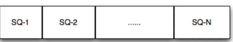
First of all, a shot based temporal segmentation is carried out on the considered query clip. Each shot obtained is then considered as a sub-query clip (elementary query).
Figure 1. The query temporal segmentation.
For every sub-query clip, SQ-i, a search in the video data-base is carried out, following the procedure previously described. The same procedure is performed considering also every couple of adjacent sub-query clips (SQ-1+SQ-2, SQ-2+SQ-3, …), then every set of three adjacent sub-query clips (SQ-1+SQ-2+SQ-3, …), and so on.
The same procedure is performed also considering the query clip, Q, as a unique video segment. The results of these investigations are then evaluated jointly, with the aim to decide if the query has a unique video segment in the data-base directly corresponding to it (considered as the entire query clip), or if it represents a partial query.
A) There is a significant correspondence between the matching obtained considering the query as a unique clip with respect to the partial matching obtained searching for sub-query correspondences. In this case the method declares that the query has been matched successfully as a whole, and there are not dummy segments.
B) There are some discrepancies, and then some further steps of investigation are needed.
In particular, there are various possibilities, depending on the number of shots, and on the fact that the evaluation performed considering the query clip as a unique video segment is in accordance or not with at least one or more of the sub-query clip matching.
As mentioned, there are various possibilities.
B1) The evaluation performed considering the query clip as a unique video segment is in accordance with at least one or more of the sub-query clip matching.
In this case, if there is an accordance between some of the adjacent sub-query clips matching, then the method declares that we have a partial query, and the matching corresponds to the adjacent sub-query clips matching with the maximum temporal span. The other sub-query clips are declared as dummy segments.
B2) The evaluation performed considering the query clip as a unique video segment is not in accordance with any of the sub-query clip matching.
In this case there are two possibilities to be taken into account, namely: B2a) The query is not present at all in the data-base;
B2b) The query is partial, and the dummy segments make the method that search for Q in the data-base fails.
In this case, if there is an accordance between some of the adjacent sub-query clips matching, then the method declares that we have a partial query, and the matching corresponds to the adjacent sub-query clips matching with the maximum temporal span. The other sub-query clips are declared as dummy segments.
3 Computational
complexity
of
the
proposed
technology
In this section, we present the evaluation of the computational complexity for the proposed method.
The complexity of the DCD and CLD features extraction are determined by the numeric algorithms proposed in the MPEG-7 standard from which they are taken; refer to [MPEG7-01], [MPEG7-XM-01], [CTD-2001]. For our proprietary motion features, the extraction complexity is very low; in the MAM case, given a sequence of m P- and B-frames (m=11 for a 12-frames GOP), in which r times c motion vectors magnitudes (one for each macroblock) are considered for the feature evaluation, a single feature is constructed by means of 3rc multiplications, mrc additions and rc square root evaluations. On the other hand, for the DMA the figures are even lower: only 1 multiplication for the time normalization and 2rc+m additions. The bitstream partial decoding time to obtain the forward motion vectors has also to be considered for both features.
Concerning the matching procedures, for the DCD feature the proposed metric is the Earth Mover Distance (EMD), applied in a 3-D space (the Luv color space) on histograms with 8 non-empty bins, with the standard Euclidean metric as the ground distance. Given a query signature composed by lq features (that is I-frames) which is to be compared to a video signature composed by lv
features, according to the sliding window approach described above, lq-lv+1 distances need to be
evaluated. Every distance is the sum of individual EMDs, normalized by lq. Therefore, the overall
number of individual distances (EMDs in the DCD case) that are evaluated for a single matching operation is lq(lq-lv+1). The minimum distance among the lq-lv+1 obtained values is finally
searched; the complexity of this task is negligible. The EMD itself is known to be the solution of a linear programming problem, whose complexity is thus polynomial. The implementation used in this system is taken from [EMD-1998]. The EMD evaluation largely overweighs all the other computations involved, e.g., taking the sum of individual EMDs.
The same matching procedure applies to the other features, namely MAM, DMA and CLD.
However, in the motion features case the individual descriptor distances are standard Manhattan norms. Therefore, for MAM and DMA the individual distance is evaluated by n subtractions and absolute value taking, with n=4 for DMA and n=rc (where r and c are the vertical and horizontal dimensions respectively of the MAM, which depend on the considered frame size). In the CLD case, the implemented individual distance is the sum of three weighed Euclidean distances; each evaluation is composed by 26 additions/subtractions, 19 multiplications and 3 square root takings.
4 Requirements achieved by the proposed technology
4.1
Common Requirements
Uniqueness (Reproducibility)
A visual signature descriptor shall provide a unique "fingerprint" which identifies an item of visual media.
Robustness
Visual signatures shall be robust to all common editing operations that may be performed on the media.
The proposed video signature allows to reach any temporal segmentation and has been tested at the GOP resolution level, and therefore it is robust to the common editing operations.
Independence
Visual signatures shall also have the property of independence: namely, that signatures extracted from visual media items which are not modified copies of one another shall be different.
As shown by the simulation results, the proposed VS is strictly related to the considered video clip, and with respect the Independence requirement.
Fast matching
Signatures shall support very low complexity comparison (distance computation) to allow large volumes of visual media to be searched rapidly.
The proposed method for distance computation between two video signatures requires a quite reduced computational complexity, and therefore large volumes of visual data can be rapidly compared.
Fast Extraction
The extraction complexity of the visual signature shall be minimal. This will ensure that extraction of signatures from rapidly growing collections remains feasible.
As required, the proposed VS extraction method does not require huge computation complexity. Compactness
Signatures shall be minimal in size. The proposed VS is quite compact. Non-Alteration
Creation of signatures shall not require any modification of the visual media themselves.
The creation of the proposed VS does not require any modification of the considered visual media. Self-Contained
Signatures shall be self-contained, in the sense that no access to the visual media (content) shall be necessary for matching.
As required, the matching method does not require any access to the visual content of the considered video clip.
Coding Independence
Extraction and matching of signatures shall be independent of the encoding/format of the visual media.
The extraction and matching of the proposed VS is independent of the encoding/format of the considered visual media.
4.2
Video Signature Specific Requirements
UniquenessNo additional specific requirements Robustness
A list of specific modifications to which the signature should be robust (and their severity) is given in the appropriate section.
The conducted tests show some level of robustness with respect to some of the proposed modifications.
Independence
It is expected that at the rate of false positive matches ≤ 1 ppm (part per million). The precise evaluation is in progress.
Fast matching
It is expected that the matching algorithm to be provided can match 1,000 clip pairs in a second on a PC-class computer (CPU<=3.4GHz) in the case of partial content matching.
The precise evaluation is in progress. Fast Extraction
No additional specific requirements Compactness
Descriptor size shall be ≤ 30kb (1 kb = 2^10 bit) per second of content on average over the entire data set.
As described in Section 5, the proposed VS size is less than 30 Kbits/seconds. Partial Matching
The video signature shall support the detection of a duplicated temporal segment of video embedded within a longer segment.
The precise evaluation is in progress. Temporal Localisation
The video signature shall support temporal localisation of partial matches (including determination of the duration of the duplicated segment).
The approach can work at any temporal resolution level, so it should be able to obtain a precise partial match localization.
5 Performance evaluation of the proposed technology
In this section we present some results of the experimental evaluation, according to the criteria specified in [MPEG-VS-08].5.1
General considerations
In this Call for Proposals, a database of original video clips is compared with query clips which are assumed to be derived from the original videos.
For each comparison between the query clip and the original clip, the proposed algorithm is required to output a binary decision:
a) clips are related (i.e., clips contain modified segments of one another), b) clips are not related.
Moreover, the Call for Proposals is evaluated under two different query scenarios, the direct content matching and the partial content matching.
The direct content matching is a case in which the whole segment of the query clip matches with a certain part (segment) of the original clip. The algorithm is required to output the start point of the matched segment in the original clip.
The partial content matching is a case in which only a part (one segment) of the query clip matches with a certain part (segment) of the original clip. This means that a query clip contains additional content not present in the original clip.
For each of the two query scenarios, this Call for Proposals is evaluated under 3 different durations of the segment to be matched (D), i.e., D=2 seconds, 5 seconds, and 10 seconds. This means that the Call for Proposals is evaluated under 6 different query types independently.
In the case of partial content matching, the durations D=2 seconds, 5 seconds, and 10 seconds are the minimum durations of the segment to be matched which are given to the algorithm (the algorithm searches for any matching segment longer than these given durations, e.g., segment longer than 2 seconds in case of D=2 seconds), and the total duration of the query clips is 30 seconds. Note that the durations of the original clips are > 3 minutes.
For the match to be considered a success, the output time position of the match must satisfy the conditions reported in [MPEG-VS-08].
Performance Measures
The following performance measures will be used. • Success Ratio
The success ratio is measured for each modification and level for each of the 6 different query types. Let us assume that there are M original clips (M=545) and M “modified” query clips. To compute the success ratio, the number of successful matches (K) is counted, using the criteria mentioned above. The success ratio (SR) is defined as,
SR = K / M (5).
The success ratio shall be calculated for all modifications and levels (22 categories) for all 6 query types. The overall success ratio is the average of the mean success ratios of the 6 query types.
• Extraction & Matching complexity
Complexity of the extraction and matching should be given for all proposed algorithms. This can be expressed in terms of number of multiplications and additions and complexity-order formulas. Furthermore, it is expected that the algorithm can match 1,000 clip pairs in a second on a PC-class computer (CPU <= 3.4GHz) in the case of partial content matching where the total duration of the query clip is 30 seconds.
• Descriptor size
Each proposer should give the number of bits required for representing the descriptor. The descriptor size shall not exceed 30 k (30*2^10) bits per second of content. In our case, we have this data.
Let’s suppose to have a clip of 1 second duration characterized by the proposed descriptors: Dominant Color, Color Layout, Motion Map and Motion Direction. The size of such clip can be estimated considering the following approximate items:
- Mpeg 7 description (text): less than 0.1 Kbyte/sec - Dominant Color (text): ~ 0.01 Kbyte/sec
- Color Layout (text): ~ 0.01 Kbyte/sec
- Motion Map and Direction (binary): ~ 0.4 Kbyte/sec
The sum of these 4 items provides the size of 1 second clip considered, that is approximately 0.52 kbyte/sec, which is much less than 30 kbyte/sec.
In this computation the temporal segmentation at different levels has not been considered because it is negligible: the temporal decomposition is useful only when it is provided at higher level descriptions, where the byte occupancy is very small within the whole considered video.
5.2
Simulation results on Independence Test
Some simulation results obtained considering the problem of Direct Content Matching and using only the DCD are reported in Table 3.
Table 3. Simulation results (Independence set; 2 sub-sets: 2, 5 seconds, respectively).
LENGTH N. QUERIES SUCCESSES
2 seconds 77 77
5 seconds 77 77
10 seconds 0 0
30 seconds 0 0
As we can see, for the considered queries, the matching results are very good.
5.3
Simulation results on Robustness Test
In the robustness test, detection capabilities in the presence of various modifications are evaluated [MPEG-VS-08].
In the robustness test, some video clips representing various types of content (film, news, documentary, cartoons, sport, home video, etc.) are selected. The duration of the clips is 3 minutes. From each clip, 3 segments of duration 2 seconds, 5 seconds and 10 seconds are selected. Each of these segments is then combined with other materials (not present in the original database) to form a total of 3 new combined segments with 30 seconds duration. The format (image resolution, frame rate, interlaced/progressive) of the combined segments is determined by the format of the selected segment (i.e., that of duration of 2, 5 or 10 seconds).
As a result, 6 new short clips of durations 2 seconds, 5 seconds, 10 seconds, and 3×30 seconds are derived, each corresponding to the 6 query types. Each of these short clips is then subjected to the modifications described in [MPEG-VS-08] to create the query clips.
The modified query clips are compared with the original clips at the operational parameters determined in the independence test.
Some simulation results obtained considering the problem of Direct Content Matching and using the DCD are reported in Table 4.
Table 4. Simulation results (Robustness set, 3 sub-sets: 2, 5, 10 seconds, respectively).
ATTACK TYPE STRENGTH N. QUERIES SUCCESSES Analog VCR Capture Light 4 3 Medium 4 2 Heavy 4 2 Brightness Change Light 20 11 Medium 15 7 Heavy 15 0 Camera on Capture Light 4 0 Medium 0 0 Heavy 4 0 Frame Reduction Light 0 0 Medium 0 0 Heavy 0 0
Interlaced Progressive Conversion N/A 13 9
Monochrome N/A 15 2
Medium 8 7
Severe Compression
Light 8 8
Medium 16 12
Heavy 16 12
Text Logo Overlay
Light 10 10
Medium 10 7
Heavy 10 7
ATTACK TYPE STRENGTH N. QUERIES SUCCESSES Analog VCR Capture Light 4 3 Medium 4 2 Heavy 4 2 Brightness Change Light 15 13 Medium 15 9 Heavy 15 0 Camera on Capture Light 4 0 Medium 0 0 Heavy 4 0 Frame Reduction Light 0 0 Medium 0 0 Heavy 0 0
Interlaced Progressive Conversion N/A 13 9
Monochrome N/A 15 1
Resolution Reduction Light 8 8
Medium 8 7
Severe Compression
Light 8 8
Medium 16 12
Heavy 16 12
Text Logo Overlay
Light 10 9
Medium 10 8
Heavy 10 7
ATTACK TYPE STRENGTH N. QUERIES SUCCESSES Analog VCR Capture Light 4 3 Medium 4 2 Heavy 4 2 Brightness Change Light 15 14 Medium 15 12 Heavy 15 0 Camera on Capture Light 4 0 Medium 0 0 Heavy 4 0 Frame Reduction Light 0 0 Medium 0 0 Heavy 0 0
Interlaced Progressive Conversion N/A 13 9
Monochrome N/A 15 1
Resolution Reduction Light 8 8
Medium 8 8
Severe Compression
Light 8 8
Medium 16 12
Heavy 16 12
Text Logo Overlay
Light 10 10
Medium 10 8
Conclusions
In this document we have presented and partially evaluated this video signature system, proposed by SCL-DEA University of Brescia (Italy).
More simulation results will be provided during the MPEG pre-meeting and meeting.
References
[MPEG-VS-08] MPEG Video Sub-Group, “Updated Call for Proposals on Video Signature Tools”, ISO/IEC JTC1/SC29/WG11 MPEG 2008/N10155, October 2008, Busan, Korea.
[MPEG7-01] “Text of ISO/IEC 15938-3/FDIS Information technology – Multimedia content description interface – Part 3 Visual”, ISO/IEC/JTC1/SC29/WG11 Doc. N4358, July 2001, Sydney, Australia.
[MPEG7-XM-01] Akio Yamada, Mark Pickering, Sylvie Jeannin, Leszek Cieplinski, Jens Rainer Ohm, Munchurl Kim, “MPEG-7 Visual part of eXperimentation Model Version 9.0”, ISO/IEC JTC1/SC29/WG11/N3914, January 2001, Pisa, Italy.
[MPEG7-book-02] B.S. Manjunath, Philippe Salembier, and Thomas Sikora, “Introduction to MPEG-7 – Multimedia Content Description Interface”, John Wiley & Sons, LTD, 2002.
[CTD-2001] B.S. Manjunath, Jens-Rainer Ohm, Vinod V. Vasudevan, Akio Yamada, “Color and Texture Descriptors”, IEEE Trans. On CSVT, pp. 703-715, Vol. 11, No. 6, June 2001.
[MD-2001] Sylvie Jeannin, Ajay Divakaran, “MPEG-7 Visual Motion Descriptors”, IEEE Trans. On CSVT, pp. 720-724,Vol. 11, No. 6, June 2001.
[BXL-2005] S. Benini, Li-Qun Xu, R. Leonardi, “Using Lateral Ranking for Motion-Based Video Shot Retrieval and Dynamic Content Characterization”, Proc. CBMI-2005, Riga, Latvia, June 21-23, 2005.
[MAM-2002] Wei Zeng, Wen Gao, Bedin Zhao, “Video Indexing by Motion Activity Maps”, Proc. ICIP-2002, Rochester, NY, USA, Sept. 2002.
[EMD-1998] Yossi Rubner, Carlo Tomasi, Leonidas J. Guibas, “A Metric for Distributions with Applications to Image Databases”, Proc. IEEE ICCV, Bombay, India, 1998.