http://pii.sagepub.com/
Control Engineering
Engineers, Part I: Journal of Systems and
Proceedings of the Institution of Mechanical
http://pii.sagepub.com/content/225/3/443
The online version of this article can be found at:
DOI: 10.1177/2041304110394531
2011 225: 443
Proceedings of the Institution of Mechanical Engineers, Part I: Journal of Systems and Control Engineering
M Tiboni, A Borboni, M Mor and D Pomi
An innovative pneumatic mini-valve actuated by SMA Ni-Ti wires : design and analysis
Published by:
http://www.sagepublications.com
On behalf of:
Institution of Mechanical Engineers
can be found at:
Engineering
Proceedings of the Institution of Mechanical Engineers, Part I: Journal of Systems and Control
Additional services and information for
http://pii.sagepub.com/cgi/alerts Email Alerts: http://pii.sagepub.com/subscriptions Subscriptions: http://www.sagepub.com/journalsReprints.nav Reprints: http://www.sagepub.com/journalsPermissions.nav Permissions: http://pii.sagepub.com/content/225/3/443.refs.html Citations:
What is This?
- Jun 13, 2011
Version of Record
>>
443
An innovative pneumatic mini-valve actuated
by SMA Ni-Ti wires: design and analysis
M Tiboni*, A Borboni, M Mor, and D Pomi
Mechanical and Industrial Engineering Department, Universita` degli Studi di Brescia, Brescia, Italy
This paper was originally commissioned for a Special Issue on Research and Education in Mechatronics and is an extended version of a paper presented at the 10th International Workshop on Research and Education in Mechatronics (REM 2009) held in September 2009.
The manuscript was received on 6 June 2010 and was accepted after revision for publication on 3 November 2010. DOI: 10.1177/2041304110394531
Abstract: This paper presents a proof of concept study on an innovative pneumatic mini-valve. The novelty aspects lie in the creation of an actuation device based on wires formed from the shape memory alloy (SMA) Ni-Ti and in the shape of the body of the valve, with its very limited dimensions being made possible by its construction using mouldable polymeric materials. The proposed device has the following advantages: easy assembly, compactness, silent functioning, bio-compatibility, low power activation, and it is cheap to produce. Extensive static and dynamic characterizations of the valve are performed using a dedicated test rig. Several different valves were measured to ensure measurement reproducibility. The static characteristics of the SMA-based valve are equivalent to those of commercially available valves. A 10 ms activation time and a 90 ms settling time are obtained at a 30 per cent duty cycle and a 1.5 Hz frequency.
Keywords: pneumatics, valves, Ni-Ti wires, shape memory alloy
1 INTRODUCTION
There has been a considerable amount of effort expended on the innovative design of pneumatic systems in recent years. One area of particular interest is the use of shape memory alloys (SMAs) in the actuator devices used in pneumatic systems [1]. There is an extensive literature on this topic. Yokota et al. [2] used SMA Ni-Ti wires to develop a small proportional actuator that showed very good static and dynamic performances and a maximum working frequency of 40 Hz. In 1997 the NiTi Alloy Company produced a thin film SMA-based micro-valve for application in the area of fluid flow control [3]. Krulevitch et al. [4] designed a valve with a membrane
formed from a Ni-Ti-Cu and silicon composite; the valve is opened by heating the membrane and triggering the shape memory effect. Other reports on the application of SMA wires in pneumatic valves include Ferraresi et al. [5] and Maffiodo [6].
The general design of a SMA-controlled valve consists of the following stages:
(a) the choice of the valve structure (spool or poppet type);
(b) the choice of the actuation device; (c) the selection of the alloy;
(d) the design of the geometry; (e) the dimensioning;
(f) the static and dynamic characterization. This paper presents the design and characterization of a prototype 2/2 pneumatic valve that is actuated by means of SMA wires made from Ni-Ti fibres. The design of this prototype requires innovative choices of shape, materials, and opening device. The body has a very compact shape that could only be obtained by using a mouldable polymeric material. The considered pneumatic device is a two-way mono-stable poppet valve [7] with the Ni-Ti wires fixed on the plug and then integrated into the body *Corresponding author: Mechanical and Industrial Engineering
Department, Universita` degli Studi di Brescia, Via Branze 38, Brescia 25123, Italy.
email: [email protected]
This paper was originally commissioned for a Special Issue on Research and Education in Mechatronics and is an extended version of a paper presented at the 10th International Workshop on Research and Education in Mechatronics (REM 2009) held in September 2009.
1
An innovative pneumatic mini-valve actuated
by SMA Ni-Ti wires: design and analysis
M Tiboni*, A Borboni, M Mor, and D Pomi
Mechanical and Industrial Engineering Department, Universita` degli Studi di Brescia, Brescia, Italy
This paper was originally commissioned for a Special Issue on Research and Education in Mechatronics and is an extended version of a paper presented at the 10th International Workshop on Research and Education in Mechatronics (REM 2009) held in September 2009.
The manuscript was received on 6 June 2010 and was accepted after revision for publication on 3 November 2010. DOI: 10.1177/2041304110394531
Abstract: This paper presents a proof of concept study on an innovative pneumatic mini-valve. The novelty aspects lie in the creation of an actuation device based on wires formed from the shape memory alloy (SMA) Ni-Ti and in the shape of the body of the valve, with its very limited dimensions being made possible by its construction using mouldable polymeric materials. The proposed device has the following advantages: easy assembly, compactness, silent functioning, bio-compatibility, low power activation, and it is cheap to produce. Extensive static and dynamic characterizations of the valve are performed using a dedicated test rig. Several different valves were measured to ensure measurement reproducibility. The static characteristics of the SMA-based valve are equivalent to those of commercially available valves. A 10 ms activation time and a 90 ms settling time are obtained at a 30 per cent duty cycle and a 1.5 Hz frequency.
Keywords: pneumatics, valves, Ni-Ti wires, shape memory alloy
1 INTRODUCTION
There has been a considerable amount of effort expended on the innovative design of pneumatic systems in recent years. One area of particular interest is the use of shape memory alloys (SMAs) in the actuator devices used in pneumatic systems [1]. There is an extensive literature on this topic. Yokota et al. [2] used SMA Ni-Ti wires to develop a small proportional actuator that showed very good static and dynamic performances and a maximum working frequency of 40 Hz. In 1997 the NiTi Alloy Company produced a thin film SMA-based micro-valve for application in the area of fluid flow control [3]. Krulevitch et al. [4] designed a valve with a membrane
formed from a Ni-Ti-Cu and silicon composite; the valve is opened by heating the membrane and triggering the shape memory effect. Other reports on the application of SMA wires in pneumatic valves include Ferraresi et al. [5] and Maffiodo [6].
The general design of a SMA-controlled valve consists of the following stages:
(a) the choice of the valve structure (spool or poppet type);
(b) the choice of the actuation device; (c) the selection of the alloy;
(d) the design of the geometry; (e) the dimensioning;
(f) the static and dynamic characterization. This paper presents the design and characterization of a prototype 2/2 pneumatic valve that is actuated by means of SMA wires made from Ni-Ti fibres. The design of this prototype requires innovative choices of shape, materials, and opening device. The body has a very compact shape that could only be obtained by using a mouldable polymeric material. The considered pneumatic device is a two-way mono-stable poppet valve [7] with the Ni-Ti wires fixed on the plug and then integrated into the body *Corresponding author: Mechanical and Industrial Engineering
Department, Universita` degli Studi di Brescia, Via Branze 38, Brescia 25123, Italy.
email: [email protected]
This paper was originally commissioned for a Special Issue on Research and Education in Mechatronics and is an extended version of a paper presented at the 10th International Workshop on Research and Education in Mechatronics (REM 2009) held in September 2009.
M Tiboni, A Borboni, M Mor, and D Pomi 444
of the valve. The selection of SMA wires as the actuation device instead of SMA springs is due to the higher force exerted by the wires and to their lower mass. A Ni-Ti-NOL alloy was chosen for the wires, and this choice is discussed in detail in section 2.
An important factor in the overall performance of a valve is the suitability of the spring used for the return of the valve: it exerts a pre-stress action on the Ni-Ti wires to guarantee the closed configuration. The resistance of the Ni-Ti alloy ensures that the electrical input is converted into heat and thus the wires contract pulling the plug to open the valve and initiating flow [8]. When the wires cool the reverse operation is performed and the valve again becomes closed.
An appropriate choice of variable is required if valid comparisons are to be made about the behaviour of a value [9]. The International Standard indicates the flow capacity and the main time values as characteristic parameters for the quasi-static analysis and dynamic analysis of a valve, respec-tively. The static tests performed in this paper have led to the experimental determination of the flow-rate that passes through the valve under various working conditions and allowed the estimation of the load loss and flow behaviour. The performed dynamic tests have allowed evaluation of the activa-tion and deactivaactiva-tion time, the settling time, and the maximum activation frequency.
2 SMA MATERIALS
SMAs undergo a plastic deformation at a relative low temperature and have the unusual property of reverting to their original shape or size when submitted to the appropriate thermal procedure. In other words, the metal ‘remembers’ its original shape and this property is called the shape memory effect (SME). This effect can be associated with a tempera-ture and stress-dependent phase change between martensite and austenite phases. The low tempera-ture phase (martensite) is relatively soft whereas the high temperature phase (austenite) is relatively hard with a highly ordered crystalline structure.
The shape recovery occurs at the austenite temperature (transformation temperature) Ta. For
the case where the alloy is reheated above Ta, the
alloy regains its highly ordered crystalline austenite structure and the SMA returns to its original pre-deformation shape in which it was originally formed. The ‘training’ of the SMA, i.e. the original formation at high temperature, is a very important process.
The SME was first observed in samples of gold-cadmium alloys and subsequently in copper-zinc
alloys. The material of interest in this paper is a Ni-Ti alloy, the so called Ni-Ti-NOL alloy (named after the laboratory in which the discovery was made the US Naval Ordinance Laboratory (NOL)). The great advan-tages of the Ni-Ti-NOL alloy are its relatively cheap constituent elements and a much larger shape memory strain than normally observed in alloys (8 per cent and in some cases up to 10 per cent). Furthermore, series fabrication is possible using common techniques.
SMA materials have been applied in many fields including medicine, robotics, mechanics, pneu-matics, vibration control, aeronautics, etc. Informa-tion related to the behaviour of commercial SMA materials can be found in [10–12].
3 LAYOUT OF THE SMA-WIRE-ACTUATED VALVE
The mini-pneumatic valve was initially conceived for application in industrial environments but it is now used in numerous other areas. As a consequence, great attention has been paid to devising a simple assembly process that can be incorporated into low-cost commercial production. The assembly method of the valve presented in this paper takes into account the possibility of using a transfer machine with simple pick-and-place components for its commercial manufacture.
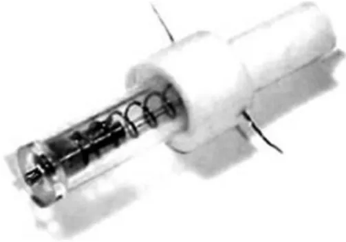
Figure 1 shows a picture of the assembled mini-valve and Fig. 2 is an expanded view; the Ni-Ti wires are clearly visible in both images. The mounted valve has a length of 20 mm and weighs 3 g. The valve components can be seen in Fig. 3; their dimensions can be qualitatively deduced by comparison with the 2 euro cent coin (18 mm in diameter). Seven elements compose the valve; the wires (3) are made from Ni-Ti fibres, while the body of the valve (5) is made from a polymeric material.
Fig. 1 Picture of the pneumatic mini-valve actuated by the Ni-Ti wires
2 M Tiboni, A Borboni, M Mor, and D Pomi
The time taken to manually assemble the compo-nents is about 1 min, with the related steps consist-ing in the followconsist-ing phases:
(a) with a needle, insert the two Ni-Ti wires first through the plug hole, then through the spring and finally through the valve body;
(b) wind the Ni-Ti wires around the copper wires, and fix the heads of the Ni-Ti wires on the brass plug with the conical pin;
(c) in the final operations, the valve is inserted into the Plexiglass body and the cap is added on the opposite side, with subsequent sealing of points at which air loss could occur.
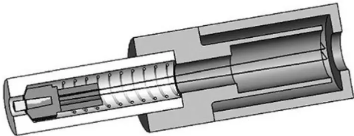
The wires actuate the poppet of the valve (Fig. 4), by opening it when they are heated and the spring closes the valve when the wires cool.
In this preliminary proof of concept study, the body of the valve has been made from polyamide which is an easily mouldable plastic material. Furthermore, this material is compatible with rapid prototyping systems.
4 FORCES AND VALVE DIMENSIONING
During the on-phase of the valve, the force F that has to be exerted by the Ni-Ti wires to move the plug, has to be larger than the combined spring force and the force due to the air pressure that is trying to keep the plug stationary. Equation (1) allows the calcula-tion of the maximum force Fmexerted by the spring
(Dl and k are respectively the extension and the elastic constant of the spring). The calculated values of Fm were between 0.91 and 1.27 N. Equation (2)
leads to the force due to the pressure.
Fm~k|Dl ð1Þ
Fp~P|Apl ð2Þ
F~k|DlzP|Apl ð3Þ
Fig. 2 Expanded view of the pneumatic mini-valve actuated by the Ni-Ti wires
Fig. 3 Components of the valve: 1 brass shutter; 2 conical steel plug; 3 Flexinol wire W50 mm; 4 valve body in Plexiglass with flow exit orifice; 5 internal valve body; 6 spring; 7 stopper with a hole W4 mm for air entry
M Tiboni, A Borboni, M Mor, and D Pomi 446
where Fpis the product of the pressure P on the plug
area Apl.
In equation (3), the plug area Apl and the spring
stretch are fixed, the maximum force that the wires can tolerate is known, hence, the elastic coefficient k is chosen to be as low as possible to obtain a wide pressure range. A return spring (a passive mechan-ical component) keeps the wires correctly stretched and the plug in the closed position by exerting the necessary force and also allows valve opening after the activation of the Ni-Ti due to its compliance. The values of the parameters used for the proto-type valve were: k 5 0.626103N/m, A
ott5 9 mm2,
and Dl 5 2 mm.
The stretching properties of four types of spring were tested. In these tests the internal diameter and the length had to remain unchanged since they are fixed by the internal size of the Plexiglass housing and the housing of the closing-pin, respectively. Once a good compromise between the spring stability and the linearity of the force–length ratio is obtained it is possible to avoid lateral bending of the spring: after the valve activation, the Ni-Ti wires contract and move the plug. Although the use of the spring is essential for the return to the starting condition of the Ni-Ti wires, this could be a source of undesired phenomena: as a matter of fact some tests, with a work frequency higher than 1 Hz, have shown noteworthy lateral bending of the spring and this undesired behaviour is emphasized by an increasing differential pressure.
In order for the system to work the Ni-Ti wires must overcome the maximum force obtained using equation (3). In this equation, the only changing parameter in the valve configuration is the pressure which increases as a function of the diameter and characterizes therefore the limit condition, since it is associated with the maximal air pressure resulting when the wires start yielding.
The chosen configuration of the wires consisted of two segments with 100 mm length. The Ni-Ti wires show a self-contraction of 8 per cent per cycle during the first 100 cycles; in fact a tested four-wire version
of the proposed valve with shorter wire lengths (36 mm) was tested and displayed unsatisfactory behaviour created by these displacements.
5 EXPERIMENTAL ANALYSIS
A dedicated test rig was built to study the static and dynamic behaviours of the valve in order to identify the important parameters and input–output vari-ables of the prototype device.The flowrate through the valve under different working conditions, the load loss, and the flow behaviour were experimen-tally determined using static tests. The shifting time, the maximum activation frequency, and the extent to which the step response speed and changes in the activation frequency of the device could be con-trolled were established by means of the dynamic tests.
5.1 The pneumatic test rig
The test rig (Figs 5 and 6) was designed so as to create a common measurement interface for the considered parameters. It consists of four main parts.
1. The electrical feed circuit: a PWM system [13] with variables programmable through a microchip supplies the SMA wires with a constant current-step (Iconst) at a frequency f 5 1/(Ton+ Toff) and
with a duty cycle that is changeable for a fixed number of cycles.
2. The fluid control system: compressed air is generated and the input pressure P1 of the dry
and filtered air is regulated. Fig. 4 Section of the mini-valve actuated by wires
Fig. 5 A picture of the test rig
4 M Tiboni, A Borboni, M Mor, and D Pomi
3. The measurement equipment: pressure P2 and
flow Q at the output of the valve are measured by a pressure transducer and a mass flowmeter, respectively.
4. Data acquisition: performed by means of a PC and dedicated software.
Since the air used in the tests to determine the static and dynamic characteristics of the valve needs to have known properties and also to avoid damage to the instruments, the test rig uses compressed air that is generated from a dedicated setup. The am-bient air was filtered and compressed by a volumet-ric compressor (maximum pressure Pmax5 0.8 MPa,
power W 5 1.5 kW), and then dehumidified as re-quired by international standards, then a group formed by a filter and a pressure regulator (FR) was used to further filter the air (a 20 mm filter) and reduce the pressure. A maximum pressure of 0.6 MPa was used in the experiments.
5.2 The static tests
Figure 7 is a schematic diagram of the experimental setup used for the static and dynamic tests. Electrical signals from the PWM circuit are used to control the valve and an almost constant pressure is preserved during the test, by means of the proportional pressure regulator R set at a desired pressure value (the pressure lightly decreases as the valve is opened by the plug). The input pressure P1 is measured
using the internal transducer of the proportional electro-valve in the test rig. This choice introduces a small error into the pressure measurement. How-ever, this is considered acceptable at this step of the research, since the goal is to simply provide a proof of concept. The output pressure P2 is measured by
the pressure transducer T connected crosswise to the air flow.
The linking pipes are ISO pressure tubes (W 6 mm) that comply with the ISO standards (ISO 6358) for an easy intra pipe connection without pressure loss and for standard conditions of the internal roughness.
The flow rate Q is measured by the mass flowmeter (F). At T15 293 K (ambient temperature),
the signal C, the output pressure P2, the feeding
pressure P1, and the flowrate Q are recorded by the
data acquisition system M (Fig. 7). Static tests can provide the effective flowrate Q passing through the valve as a function of the fixed upstream pressure P1
and a measured downstream pressure P2.
From tests using W 50 mm Ni-Ti wires, it became clear that the maximum input pressure was P15
0.2 MPa (absolute and with open output) and the maximum flowrate was less than 0.41 l (ANR)/s. The comparison of results obtained in tests in calm air with those obtained using compressed air showed the follow intuitive effects:
(a) the use of compressed air increases the force required to open the plug;
(b) the recovery time of the Ni-Ti wires is reduced (due to cooling by the compressed air);
(c) a part of the energy supplied during the transition between austenite and martensite phases is lost (because the cooling effect created by the compressed air also occurs during the activation phase).
At an absolute pressure of P1 higher than
0.06 MPa, the tests revealed that the energy supplied by the Iconst5 240 mA current flowing for 200 s is not
able to activate the wires. Tests to identify the activation current limits were therefore performed. For an activation current I 5 240 mA with an input pressure P1 of 0.2 MPa the valve remained closed,
since the NiTi wires cooled down instantaneously. When the activation current was increased to 900 mA (maintaining a fixed pressure), the valve quickly opened (in about 0.05 s), but the wires became burnt after 0.5 s, even though they were constantly cooled Fig. 7 The experimental setup for the static and dynamic tests (R is the proportional pressure regulator, T the pressure transducers, V the valve, F the mass flowmeter, and M the data acquisition system)
M Tiboni, A Borboni, M Mor, and D Pomi 448
by the flow of compressed air. In a further test using an activation current of 500 mA the valve worked correctly and the wires were not damaged. This value was chosen as the activation current.
To find the flowrate using quasi-static tests, the valve was kept open until a steady state flow was reached and a 30 s recording time was used. At first, the activation current was fixed at 500 mA at an input P1 of 0.12 MPa, then the signal from the mass
flowmeter was recorded and then the input pressure was changed until the differential pressure limit was reached.
The data collected through a set of static tests, repeated on ten different examples of the valve, allowed the calculation of the flow capacity, eval-uated as KVusing the protocol in EN 60534-2-3. The
value of this parameter is taken to be a valid basis on which to compare the prototype with commercial valves. The calculation of KV according to CEI-EN
60534-2-3 requires the application of a procedure (implemented in an Excel sheet) with different steps. The main expression used for the estimation of the flow capacity is KV~ Q N9P1 1{ DP=Pð 1Þ � 3FcxT � � � � Fp ffiffiffiffiffiffiffiffiffiffiffiffiffiffi MT1Z DP=P1 s ð4Þ where Q is the flow through the valve, T1 is the
absolute temperature of the test, P1 is the absolute
input pressure, DP is the pressure drop across the valve, M is the molecular mass of the air, and N9, Fc,
xT, Fp, and Z are parameters defined by the standard,
whose values can be found in Table 2 of the standard. Moreover, the conductance of the valve can be approximately estimated, by using equation (5), where QN* is the sonic flow at absolute input
pressure P1 and KT~ ffiffiffiffiffiffiffiffiffiffiffiffiffiffiffi 293=T1 p is the temperature factor C~ Q�N P1KT ð5Þ
The value of the conductance C obtained by the estimation is C 5 2 (l(ANR)/s)/MPa.
The factors that influence the functioning of a generic valve have to be considered in the flow capacity calculations using equations that express the relationship between flowrate, flow coefficients, related installation factors, and pertinent service conditions for the valves [1].
The flow rate Q, as represented in Fig. 8, is a function of the input pressure P1, (the output
pressure P2 is fixed at 0.1 MPa): the flow rate Q
increases in a progressive manner until the pressure P1 reaches 0.16 MPa, corresponding to the critical
ratio condition between P1 and P2. Exceeding this
pressure value means a sonic flow and the flowrate becomes a linear function of (P12 P2).
Table 1 compares the prototype 2/2 mini-valve actuated by Ni-Ti wires with the same type of valve actuated by a solenoid (KVcalculated at a differential
pressure of 0.1 MPa). It is clear that the flow coefficient results are better for the prototype valve.
5.3 Dynamic tests
Tests were performed to investigate the dynamic behaviour of the prototype valve since the dynamic response of the valves is important in many industrial applications.
Fig. 8 The P–Q curve of the valve with pressure P2
equal to 0.1 MPa, where Q is the flowrate, P1is
the inlet pressure, and P2is the outlet pressure
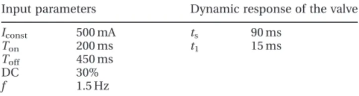
Table 2 Dynamic characteristics of the mini-valve during the test with an input pressure P1of
0.12 MPa for 100 cycles
Input parameters Dynamic response of the valve
Iconst 500 mA ts 90 ms
Ton 200 ms t1 15 ms
Toff 450 ms
DC 30%
f 1.5 Hz
Table 1 Technical data of a commercial solenoid meso-valve 2/2 and the experimental data of the SMA valve
SMA Solenoid
Medium Air Air
Function 2/2 NC 2/2 NC
Operation Direct acting Direct acting
W (mm) 2.0 1.6
Kv(l(ANR)/s) 1.35 1.2
6 M Tiboni, A Borboni, M Mor, and D Pomi
5.3.1 Step response tests
To identify meaningful step response times dynamic tests were performed that followed the procedures in ISO 12238 and used a current Iconst5 500 mA, an
input pressure P15 0.12 MPa, and a step signal
Ton5 200 ms. Figure 9 shows the response of the
valve to changes in the current step signal.
The shifting time (or activation time) is the time between the application of the electrical signal and the time at which 10 per cent of the output pressure is reached, whereas the deactivation time is the time between the application of the electrical signal and the time at which 90 per cent of the output pressure is reached.
The obtained activation time is 15 ms, which is comparable to the value for a generic commercial mini electro-valve. This parameter could be further improved by the use of more efficient wires. It proved impossible to obtain a meaningful deactiva-tion time and this is probably a result of the complex behaviour exhibited by the SMA wires on cooling [14].
The settling time ts(the time after which the step
response remains within a tolerance band of 2 per cent of the final value) is about 90 ms and corre-sponds approximately to the contraction time of the Ni-Ti wires: varying the current amplitude, the Ton
should not be slower than 100 ms with a 20 per cent margin of safety for the change of phase.
This response results in an overshooting of the pressure at the opening of the plug. A possible explanation of this phenomenon is as follows: at the activation of the valve the wire contraction, due to the high temperature, causes a large movement of the poppet, afterwards the flux of compressed air reduces the temperature of the wire with a
conse-quent reduction of the contraction resulting in a decrease in the pressure.
5.3.2 Dynamic response tests
The dynamic response behaviour of the valve was studied using tests based on on-off cycles with prefixed frequency values (Fig. 10).
Parameter values of Iconst5 500 mA and Ton5
200 ms were used to analyse the dynamic behaviour of the valve, and these values were guided by the tests reported in section 5.3.1: initially Toff was set
at 800 ms with a 1 Hz frequency, because a slow return of the plug was expected. Then, Toff was
adjusted to 450 ms, and the working frequency to 1.5 Hz and the duty cycle (DC) to almost 30 per cent. The number of cycles was limited to 100 since there is a consensus in the literature that after this point there is a significant degradation in the SME in SMAs [8, 10, 14].
The input pressure P1 was set at 0.12 bar using a
digital regulator. Sometimes, the opening of the plug was not completed; in fact its step showed smaller amplitudes, especially in the first ten cycles, before settling to the correct value.
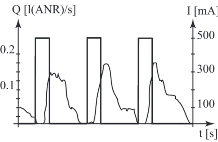
The results obtained in these experiments are shown in Fig. 11. The following points emerge from an analysis of this figure.
1. The activation phase (the opening of the plug) is repeatable and substantially constant, in fact the main times are easily extracted; the activation time t1 and the settling time ts are the same as
those extracted with the response tests.
2. The return of the wires is not repeatable and not linear in the first 100 cycles. This is due to the complex behaviour exhibited by the SMA on cooling.
Fig. 9 Pressure response to current step signal with: Iconst5 500 mA, Ton5 0.2 s, and P15 0.02 MPa.
t1is the activation time (shifting time) and tSis
the settling time
Fig. 10 Main signal time of current I and flow Q, where Tonis the electrical activation time, t1is
the activation time (shifting time), and t2is the
M Tiboni, A Borboni, M Mor, and D Pomi 450
Table 2 summarizes the values of the main times for the experiments performed at an on-off cycle frequency of 1.5 Hz, shown in Fig. 11.
These tests were performed at two different loads: a pure thermal one and a mechanical one. The former is due to the combined effect of the spring force and the pressure created by the input air flow, the latter to the martensite to austenite phase changes and vice versa. If the SMA is subjected to a group of thermo-mechanical cycles, many properties are influenced. From a metallurgical viewpoint, fatigue degrades the material resulting in softening and a more elastic behaviour is noted when the valve is dismantled and reassembled. Wires that have experienced almost 100 cycles tend to display micro-cracks and there-fore these wires are prone to breaking very easily [9]. This effect is proportional to the amount of supplied energy, and these phenomena increase with an increase in the Ton and Iconst values. The detailed
study of this fatigue problem is a topic that should be the subject of future work.
6 CONCLUSIONS
It has been experimentally verified that the proto-type valve has an activation time of 15 ms with a 1.5 Hz frequency at a 30 per cent DC. The required current for the activation of the Ni-Ti wires was almost 500 mA for 200 ms.
The key external parameters that influence the cycle life are: time, temperature, stresses and application type, deformations, and the number of cycles. The key biasing internal parameters are: the alloy composition, the thermal treatment, and the mechanical treatment. The complex
thermo-mechanical behaviour of SMAs means that it did not prove possible to obtain a simple relationship between the temperature and the displacement or between the temperature and the applied forces. The maximum SME was obtained and then the stresses and limit deformations were selected as a function of the number of working cycles. Stoeckel [15] presents useful data to describe the fatigue of SMAs: this data is used with an appropriate safety margin for the Ni-Ti wires used in the proposed valve. The wires become unusable after 100 cycles and need to be changed.
Future work in this area will concentrate on improving the operational life of the valve so that it reaches the levels displayed by commercial electro-valves (at least 20 000–40 000 cycles reaching up to 100 000 000+ cycles). Possible variations in the valve design to achieve this goal are: the choice of SMA wires with a larger cross-section, the use of a higher number of wires to open the plug (in this way the wires can work far from their limits), the selection of a more efficient SMA (even if this means a costs increase), and the forced cooling of the wires.
Other areas worthy of further investigation in-clude: the complete and rigorous characterization of the valve; and the isolation of the optimal valve configuration (a normally open valve or a valve with multiple outputs can be easily realized). A pressure P0applied to the internal surface of the plug could,
for example, replace the spring force. This would favour the miniaturization of the valve. In this case the plug must be redesigned to minimize inlet pressure effects. The absence of the spring would improve the manual assembly process.
This valve could also be used as passive compo-nent without electrical activation of the wires to realize a safety valve that triggers when a specified air flow temperature is reached. The extension of this concept to a 3/2 bistable valve would be of particular interest in this safety-related scenario. F Authors 2011
REFERENCES
1 Belforte, G. Manuale di pneumatica, 2005 (Tec-niche Nuove, Torino, Italy).
2 Yokota, S., Yoshida, K., Bandoh, K., and Suhara, M. Response of proportional valve using shape memory alloy array actuators. In Proceedings of the 13th IFAC World Congress, San Fransisco, June 1996 (Pergamon Press, Oxford).
Fig. 11 On-off cycles: the current signal (Iconst5 500 mA,
Ton5 200 ms, and Toff5 450 ms) and the flow
signal
8 M Tiboni, A Borboni, M Mor, and D Pomi
3 Johnson, A. D. and Busch, J. D. Recent progress in the application of thin film shape memory alloy. In Proceedings of the First International Conference on Shape memory and superelastic technologies, Pacific Grove, California, 7–10 March 1994, pp. 299–304 (Elsevier, Pacific Grove, California). 4 Krulevitch, P., Lee, A. P., Ramsey, P. B., Trevino,
J. C., Hamilton, J., and Northrup, M. A. Thin film shape memory alloy microactuators. J. Microelec-tromech. Syst., 1996, 5(4), 270–282.
5 Ferraresi, C., Maffiodo, D., and Manuello Ber-tetto, A. A novel pneumatic valve actuated by shape memory alloy wires. Int. J. Mech. Control, 2001, 2(1), 49–56.
6 Maffiodo, D. Sviluppo di attuatori innovativi a memoria di forma per applicazioni su componenti meccanici. PhD Thesis, Politecnico di Torino, Ingegneria industriale e dell’informazione, Mecca-nica applicata alle macchine, Torino, 2004. 7 Srinivasan, A. V. and McFarland, M. D. Smart
structures: analysis and design, 2001 (Cambridge University Press, New York).
8 Borboni, A. Meso- to micro-actuators: a theoretical and practical approach, 2008 (CRC Press, New York).
9 Johnson, A. D. and Kraemer, J. State of the art of shape memory actuators. The Sixth UK Mecha-tronics Forum International Conference, Skovde, Sweden, 1998.
10 Velazquez, R., Hafez, M., Szewczyk, J., and Pissaloux, E. Experimental and computational thermomechanical study of a SMA micro-actuator: aspect of antagonist-type behaviour. The Third MIT Conference on Computational Fluid and Solid Mechanics, Boston, Massachusetts, 2005.
11 Borboni, A. Microactuators. In The MEMS hand-book (Ed. Gad-el-Hak M), 2005 ch. 31 (CRC Press, New York).
12 Ikuta, K. Application of shape memory alloy actuator for clean gripper. The Seventh CISM– IFToMM Symposium on Theory and Practice of Robots and Manipulators, Udine, Italy, 1998. 13 Millman, J. and Grabel, A. Microelectronics, 1994
(McGraw-Hill, London).
14 Leppa¨niemi, A. Shape memory alloy: applications and commercial aspects. The Sixth UK Mechatro-nics Forum International Conference, Skovde, Sweden, 1998.
15 Stoeckel, D. Status and trends in shape memory technology. The Third International Conference on New Actuators, Bremen, Germany, 1992.
APPENDIX Notation
Apl plug area
C conductance
f frequency of the actuation of the valve
F force exerted by the NiTi wires to move the plug
Fm force exerted by the spring
Fp pressure force on the plug
k elastic constant of the spring KT temperature factor
KV coefficient for the flow capacity
Iconst amplitude of the step-current
M air molecular mass
N9, Fc, xT,
Fp, Z
parameters of the EN 60534-2-3 standard used to evaluate Kv
P pressure acting on the plug P1 absolute input pressure
P2 absolute output pressure
Q flowrate
QN* sonic flowrate
t1 activation time
t2 deactivation time
ts settling time
T1 absolute ambient temperature
Dl maximum extension of the spring DP difference in pressure on the valve