PICO HYDROELECTRIC TURBINE
Pelton WheelMOREAU Laurent
<[email protected]>
Summary
In this article you will find a summary of a pico hydro electric system which I develloped. This system is
designed to recharge a bank of batteries for power supply needed by an alpine chalet. This docuement
aims to share my work for those who might be interested in using a similar project. Within this
document, I provide ideas and informations which might be useful. I would like to clarify that I'm not a
professionnal, and that all calculations furnished are mine and therefore I'm the only person responsible
Version Française Table of content 1. Introduction 1.1. Site setup 1.2. Technic choices 2. Theory (calculations) 2.1. Introduction 2.2. Estimation of potential 2.3. The speed of the water 2.4. Angular velocity
2.5. Cross sectional area of the injectors 2.6. Torque
3. Mechanical Parts 3.1. Structure
3.1.1. Drawings of the overall system 3.1.2. Axal support
3.1.3. Flancs - Sides 3.1.4. Injector supports 3.2. Axle
3.3. Injectors 3.3.1. The right section 3.3.2. Profile Section 4. Alternator
4.1. Introduction
4.2. Classic car alternator ( brushes + inductor) 4.2.1. Caractéristiques
4.2.2. Advantages 4.2.3. Disadvantages
4.3. Modified car alternator (permanent magnet) 4.3.1. Avantages
4.3.2. Inconvénients 4.3.3. Exemples de matériels 4.4. Alternators used in boat building 4.5. Moteur Bruschless
5. Experimentation and development 5.1. November 2003 5.2. January 2004 5.3. March2004 5.4. April 2004 5.5. Mai 2004 5.6. June 2004 5.7. August 2004 6. Pictures 7. Links
7.1. Informations and formulas 7.2. dealers & suppliers 7.2.1. Wheels 7.2.2. Alternators 7.2.3. Full turbines
Figures List
2.1. Formula to estimate potential
2.2. Maximum power (without loss to the system) 2.3. Power efficiency indexed to 80%(h= 0,8) 2.4. Power efficiency indexed to 60%(h= 0,6) 2.5. Vitesse de l'eau
2.6. Specific water speed 2.7. Angular velocity
2.8. Rotational speed, specific to the wheel 2.9. Rotational speed
2.10. Rotational speed
2.11. Cross sectional area of the injector 2.12. Specific cross sectional area for my injector 2.13. Diameter of the injector
2.15. Force of the water jet 2.16. Choc du jet spécifique
2.17. Formula to calculate relative torque 2.18. Formule spécifique relative au couple 3.1. View from below
3.2. Dessin des flancs supportant l'arbre 3.3. Dessin des Flancs
3.4. Dessins des supports injecteurs 3.5. Axle
4.1. WindBlue Spécial hydro 4.2. Power curves
4.3. Hydrogenappliances Spécial hydro 4.4. Power curves
4.5. photo de l'alternateur "Leece-neville" modèle 110-521 présenté sur le site proship 4.6. Diagramme Courant/Vitesse de rotation/Couple
4.7. Brushless motor - 4 pôles 5.1. Essai en charge, moteur DC 50 w 5.2. Turbine avec moteur DC 165 W 6.1. begining ...
6.2. More ...
6.3. Turbine with DC 50 watts motor 6.4. Turbine with DC 165 W motor 7.1. 220 V AC - 50Htz - 1500W Chapitre 1. Introduction
Table of content
1.1. Site setup 1.2. Technic choices
This pico hydro electric turbine is in the process of devellopement and is means of producieng clean energy in complete autonomy. According to my calculations, it will produce a current of 25 to 35 Amperes under a 12 Volts tension. its mins function will be to recharge a bank of battery to power on an alpine chalet in combinaision with a photovoltaique system.
1.1. Site setup
I have a natural energy source: water. It cme to my chalet through a semi rigid PVC pipes. Collection is made up and feeds a tank of a capacity of 2,500 liters.
- Pipes diameter = 19 mm intérior (25 mm external) - Drop Tank to chalet = 50 mètres - Pressure = 5
bars - Flow = 60 litres/minutes (with 12 mm injector diameter)
1.2. Technicals options
The element which will determine the "form" of my project is the "wheel". After much reflection and research, my choice was made to a Pelton wheel built in epoxy resin with a diameter of 133 mm. I found a good supplier in Australia, whose link can be found in the 'links' section. I my opinion the pelton wheel offers the best value for money (about 65 Euros), however this wheel is extremely fragile so be very careful! It is constructed using epoxy resin, very strong but also brittle (I have had some bad experiences because I did not pay attention to this characteristic). This also means that a filter system needs to be used upstream from the turbine to filter particulates (small stones and pebbles). There is an alternative whell that is less brittle but much more expensive. Lastly it should be noted that you can find the complete turbine system prebuild and ready to use for 1500 Euros.
Chapitre 2. Theory (calculations)
Table of content
2.1. Introduction 2.2. Estimation of potential 2.3. The speed of the water 2.4. Angular velocity
2.5. Cross sectional area of the injectors 2.6. Torque
2.1. Introduction
Before I could start this project I had to calculte if I could draw power from volume and pressure of flow present. So the next step to to explain the calculations and estimations made simply. If there are errors in this page please contact me via e mail, it is this way that we can improve and expand our possibilities.
Note
In the following section I will explain the general formula followed by the same formula using my 'site'
specific data.
2.2. Estimation of potential
Figure 2.1. Formula to estimate potential
This is the first formula which I used, it makes it possible to estimate the potential by considering the two parameters: volume per second and the 'Head' of water (the height of water above the turbine).
Using the international standard unit (S.I) the watt is the universal unit for 'power', this can
encompasses: Electrical, mechanic. hydraulic or otherwise.
Figure 2.2. Maximum power (without loss to the system)
In the example above I have purposely not taken into consideration energy lost from the system. (Unfortunately with all systems there will be some power lost).
Figure 2.3. Power efficiency indexed to 80%(h= 0,8)
By estimating a power effciency of 80% (h=0.8), perhaps this is rather presumptuous, it resulted in asystem producing 392 watts with a voltage of 12 V and an ampage 32.5 Amps!
Figure 2.4. Power efficiency indexed to 60%(h= 0,6)
By estimating a power effciency of 60% (h=0.6), more realistic, it resulted in a system producing 294 watts with a voltage of 12 V and an ampage 24.5 Amps! This was my last offer, I did not want to descend lower than this ;-)
2.3. The speed of the water
To calculate the speed of water leaving the nozel of the injector I used the following formula:
Figure 2.5. Vitesse de l'eau
In my scenerio:
The first value is in metres per second, then I convert this into km per hour, to visualise the speed. (it's impressive!) 2.4. Angular velocity
To calculate the angular velocity of the wheel (no load applied) I used the following formula:
This calculation is only valid for zero application of load because there is no counter force against the 'buckets' or rotors of the Pelton wheel. Thereore the water is free to follow the 'buckets' rotation resulting in no torque. However it is possible to estimate that the difference could not be more than 10 to 15% when the torque is expolitable.
Note
The tangential velocity of the whell must be equal to 0.48x V with a connected load.
Figure 2.7. Angular velocity
In my scenerio:
Figure 2.8. Rotational speed, specific to the wheel
To convert the angular velocity (frequency) to rotational speed (revolution per minute) I used the following formula:
In my scenerio:
Figure 2.10. Rotational speed
The initial value is expressed as turns per second. Next I converted into a number of revolutions per minute by mulitplying the initial value by 60, this was impressive!
2.5. Cross sectional area of the injectors
To find the diameter of the injectors I used the following equation:
Figure 2.11. Cross sectional area of the injector
In my scenerio:
Figure 2.12. Specific cross sectional area for my injector
To convert the cross sectional area into a diameter, I used the following formula:
Figure 2.13. Diameter of the injector
Figure 2.14. Diameter of my injector
I used 0,16 cm² (0,32/2) because my system has two injectors. Therefore the each injector creates a diameter of 4.5mm
Note
So if the pointing inwards with a reducing diameter, the diameter of the jet is equal to the exit hole.
However, we must take into consideration the loss of the load. In the case of an abrupt break in
diameter (the end of the tube) it is nesscessary to apply a contraction coeficient equal to 0.6.
2.6. Torque
To find the value of the torque I first need to calculate the force exerted by the injector on a flat surface at right angles to the jet of water.
Figure 2.15. Force of the water jet
Note
The value (F) is doubling for the form of the pelton wheel.
In my scenerio:Figure 2.16. Choc du jet spécifique
Note
The value of the flow is divided by two because the calculation needs to be applied to two injectors. We
have to take into consideration that the wheel will move and therefore the speed of the wheel must be
subtracted from the speed of the water.
To calculate the torque I used the following formula:
In my scenerio:
Figure 2.18. Formule spécifique relative au couple
Note
The energy on the 'buckets' or 'rotors' is not due to the pressure of the water, infact there is no water
pressure since it has been converted into rotational speed of the wheel. In fact the energy is due to the
change of direction between the entry and exit point of the water. The form: f = specific weight x
( V1.cosTêta1 - V2.cosTêta2) (I'm not too sure). What causes complication is the fact we are unsure of
the direction and speed of the water after colision with the wheel. It could be that the absolute value of
speed is constant, however the angle of exit is difficult to predict. This angle is determined by the
'buckets' or 'rotor' shape and I think, by their position and orientation in space as this is constantly
changing. Therefore we can understand that the static torque (without any rotation of the wheel) must
be high because with the form of the rotors the jet exits at 180 degrees to it's entrance to the 'bucket'
or 'rotor'. Conversely if the bucket or rotor moves freely in the direction of the water jet, this may have
a limited impact on the modification of the water jet's direction, therefore the torque is low and the
speed high.
Chapitre 3. Mechanical Parts Table of content
3.1. Structure
3.1.1. Drawings of the overall system 3.1.2. Axal support
3.1.3. Flancs - Sides 3.1.4. Injector supports 3.2. Axle
3.3. Injectors
3.3.1. The right section 3.3.2. Profile Section
3.1. Structure
structure is made from a section of aluminium 25x55 mm.
3.1.1. Drawings of the overall system
Display original size
3.1.2. Axal support
Display original size
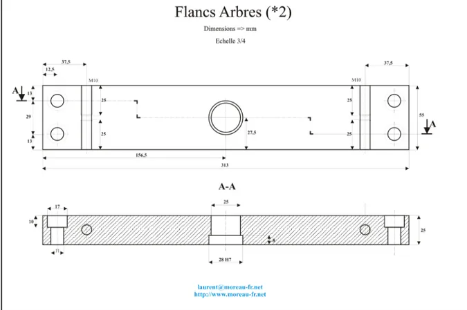
3.1.3. Flancs - Sides
Figure 3.3. Dessin des Flancs
3.1.4. Injector supports
Figure 3.4. Dessins des supports injecteurs
Display original size
3.2. Axle
The axle is supported by two bearings mounted by X
- Ø Internal = 12 mm - Ø external = 28 mm - Internal diameter of the bearing ring = H7g6 - External
diameter of the bearing ring = H7h6
Display original size
3.3. Injectors
3.3.1. The right section
Firstly I constructed some injectors using hydraulic copper piping.
3.3.2. Profile Section
Chapitre 4. Alternator Table of content
4.1. Introduction
4.2. Classic car alternator ( brushes + inductor) 4.2.1. Caractéristiques 4.2.2. Advantages 4.2.3. Disadvantages
4.3. Modified car alternator (permanent magnet) 4.3.1. Avantages
4.3.2. Inconvénients 4.3.3. Exemples de matériels 4.4. Alternators used in boat building 4.5. Moteur Bruschless
I was not sure which type of alternator would be the most efficient. As I explained in the first formula I expected there would be 30 amps of current with 12 volts produced. So the following data will give me an idea of what to use.
+ Current produced ~ 30 A + Tension = 12 V + Type of current = continuous + Speed of rotation +
Necessary torque
After research I foud three possible techologies which were appropriate. However this part of the system, being most expensive, I did not want to make an error.
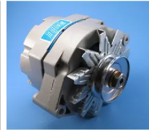
4.2. Classic car alternator ( brushes + inductor)
I found the following alternator in a garage.
4.2.1. Caractéristiques
- Manufacturer : "Bosch". - Power : 12V/90A. - Intergrated charge regulator. - Price : 120 euros. - no
torque information :-(
4.2.2. Advantages
- Regulation of the tension is possible
4.2.3. Disadvantages
- resistance due to the friction of the brushes - Wear of the brushes (maintenance) - Loss of energy due
to the induction current required
4.3. Modified car alternator (permanent magnet)
4.3.1. Avantages
Apart from the limitations of the bearing speed there are no restrictions The torque is proportional to the electrical charge
Replacement pieces are easily found in garages or at the breakers yard!
4.3.2. Inconvénients
The tension is variable
4.3.3. Exemples de matériels
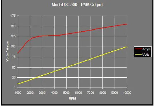
4.3.3.1. Windblue
Reaches 12 Volts at 1200 RPM The chart below represents actual output on a test stand. Voltage readings were recorded with the circuit open (No Load)while Amperage was recorded with the output shorted (Max Load). Your system setup will determine what output you will see in the “real world”. For example a dead battery will pull much more current similar to the shorted output reading than will a fully charged battery. Also the voltage will rise until it meets the voltage of your battery and then level off as the battery is “absorbing” the excess voltage as it charges. This unit can handle over 10,000 RPM with ease but since the output is unregulated you should be sure and run a 100 or 150 amp fuse on the output to prevent damage to the unit if your load becomes excessive. Also consider using a charge regulator so your batteries don’t become overcharged. On our test stand with a 12 Volt battery connected the PMA produced 120 Amps at 2000 RPM.
Figure 4.1. WindBlue Spécial hydro
Manufacturer: Windblue
4.3.3.2. Hydrogenappliances
LOTS OF LOW END POWER GENERATION ABILITY!!!! \ Capable of generating well over 12,000 Watts at speeds over 18,000 RPM. Great for charging BIG battery banks that are drained. Great for heavy amp loads! The higher the amp load the harder they work. Perfect for building simple, inexpensive and dependable wind or water turbines. A put-up and forget design! Expect decades of dependable service life. Bi-rotational. Makes power when turned in either direction. Note: Clockwise is the preferred direction since the nut tends to stay on and it cools better! All weather rated. Rain, ice and weather proof electronics. Light weight aluminum body. 17MM hardened shaft. D.C. output. Includes built in rectifier. 2.33 phase magnetic field spread for maximum efficiency +low cogging! Heavy Duty coils and diodes. Bearings rated for 115,000 hours + 14 powerful #42H Neodymium magnets. Warranty - 90 days parts and labor FOB Lancaster, CA
Figure 4.3. Hydrogenappliances Spécial hydro
Manufacturer: Hydrogenappliances
4.4. Alternators used in boat building
Manufacturer : "Leece-Neville". Power: 12V/51A ou 12/72A. Self excited adjustable tension
Brushes are a mixture of copper and graphite and are self lubricating Bearings last longer than the car alternator
Torque information is given
Prix : 376 euros (via French distributor). Manufacturer : Prestolite
Dealer : ProShip marine
There are two models avaliable (51 A et 72 A) and in reality the best model is the 51 A model as it is more adapted to this environment. Thus for 30 amperes this model requires a torque of 1.5 pounds per square foot at 2.04 N/m at a speed of 2000 rpm
Figure 4.5. photo de l'alternateur "Leece-neville" modèle 110-521 présenté sur le site proship
Display original size
I ordered this alternator from Proship : after 2 months I recieved the alternator but it was not the correct
alternator (It was not self exciting and without adjustable tension)
Self exciting is stated as 'SELF' in the in the Leece-Neville documentation. If they need 'ignition' they
are not self exciting, be careful!
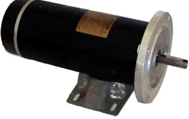
4.5. Moteur Bruschless
I found this brushless motor with a permanent magnet Manufacturer : ?
Power : 40 A à 1800 rpm for 18,75 livres/inch torque Permanent magnet
Price: $260
Figure 4.7. Brushless motor - 4 pôles
kansaswindpower
Chapitre 5. Experimentation and development Table of content 5.1. November 2003 5.2. January 2004 5.3. March2004 5.4. April 2004 5.5. Mai 2004 5.6. June 2004 5.7. August 2004 5.1. November 2003
Today I finished the mechanical part of the turbine. I just had to find a appropriate generator (if you have some information please send it to me) and connect it to the axle, then I had to design the correct form of the bodywork to contain the water.
5.2. January 2004
For the first time I mounted the turbine to test it with water it was dark and I only had a headlamp ;-0 and I was impatient to see the wheel turn. I was really impressed. It was satisfying to see the theory in practice. There was no vibration. I could not measure the speed of rotation with my eyes, but the speed was impressive! (I am going to find the speed with a strobe so I can make more precise calculations)
Note
During this experiment I was surprised by the flow of water exiting the wheel : the water continued in
the same direction in which it left the injector. After I applied some torque (friction) to the axel, the
water left the wheel perpendicular to the original flow (180 degrees)
5.3. March2004
bodywork is finished
5.4. April 2004
I took the big decision: I ordered the Leece-Neville model "110-521" via internet (12V-72A) by Proship. 2 days after the seller called me, telling me it would be a long wait : 8 to 10 weeks, so I didn't bother.
5.5. Mai 2004
Someone gave me a small step by step motor. I dedided to connect it to the turbine to carry out some tests. Theoretically , it could generate 4 amps. I searched for a fly wheel or 'cog' to link the wheel axle to the motor.
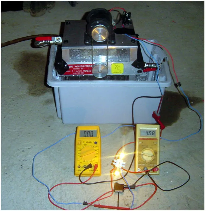
I received the Leece-Neville alternator, but there was a problem: a wire came out of the charge regulator. (no documentation was given with the product) By e mail I asked the supplier for information but they did not reply. I phoned them directly and I had a bad feeling, the response was not helpful at all. I contacted the manufacturer directly and they explained that the model I had ordered was not self excited. So I repackaged it and sent the it back. I connected the step by step motor. I used two 25watt bulbs. During this experiment I was able to produce 4.5 amps under 12 volts. After 24 hours I managed to explode the bearings but I knew this motor take this charge for a long time. But my objective was to see if it would work, and it did!
Figure 5.1. Essai en charge, moteur DC 50 w
5.7. August 2004
I came back from Bretagne with a washing machine engine made by polymotor (Italy). This one rapidly took his place on the turbine and generated 70 Wh, so 1.5 KW byday
Installation presque définitive avec voltmètre, ampermètre et compte tours intégrés.
Chapitre 6. Pictures Figure 6.1. begining ...
Figure 6.2. More ...
Figure 6.3. Turbine with DC 50 watts motor
Beautiful ;-)
Chapitre 7. Links Table of content
7.1. Informations and formulas 7.2. dealers & suppliers
7.2.1. Wheels 7.2.2. Alternators
7.2.3. Full turbines
7.1. Informations and formulas
very good site about hydolic Les roues des moulins à eaux
Directed by a retired engineer, this site is a gold mine ... You find the "calculation wheel" software with amazing features. Nantes university, web page of Claude SAINT-BLANQUET
Heat transfer specialist, its pages will get you to another world. As far as we are concerned, visit its section fluid mechanics
7.2. dealers & suppliers
7.2.1. Wheels
Australien whell dealer Rainbow Power Company
Find a wheel to the extrem side of the world by dealing with a very sympathetic character, what's best ? Ask "Dave" and tell him that you come from the "Frenchie" Moreau ...
7.2.2. Alternators 7.2.2.1. Continuous Current Manufacturer: Windblue Manufacturer: Hydrogenappliances 7.2.2.2. Alternative Current 7.2.3. Full turbines
7.2.3.1. 230Volts alternative current- 50 Hertz
Please find below links to manufacturers who cell turbine which produce alternative current
7.2.3.1.1. IREM
IREM, Italian society: http://www.irem.it
IREM SpA Via Abegg 75 - 10050 Borgone (TO) - ITALY Tel. +39 011 9648211 - Fax +39 011 9648222
Water is the ideal renewable power source to produce green energy, used by man since the beginning of time . Ecowatt water turbines, resulting from years of experience in the field, transform the energy of small streams into precious electricity, in a clean way and in full respect for the environment. These water generators are the ideal solution for those places where electrical energy is not available from the national grid. They solve the problem of energy supply in many situations, for example in isolated houses, alpine refuges and pastures, missions and small villages. Water generators can also ensure the operation of electric and electronic equipment for remote signalling, remote control and water purification. Specific water generators can operate in parallel with the grid in order to resell the green energy produced in excess. Ecowatt water turbines permit energy saving and provide green energy giving a considerable contribution to ecology, since they help avoiding the burning of vast quantities of fossil fuel and hydrocarbons, which are held to be widely responsible for air pollution, acid rain and the so-called "greenhouse effect".
7.2.3.1.2. Energie Douce
Figure 7.1. 220 V AC - 50Htz - 1500W
Dealer link : Energie Douce
7.2.3.2. Tension 12/24/48 V CC
7.2.3.2.1. Heliotron
Canadien supplier: http://www.heliotron.ca
The micro-hydro turbine PM-1000 is available in 12, 24, 48 Volts and can provide a power of 750W, from a small volume of water to charge batteries. A flow of water as small as 100 GPM flowing by gravity into a pipe 10 feet in height, or 5 GPM flowing in a pipe 200 feet high, can provide enough energy to cover electricity needs a small house. In the regions long rainy season and regions where there are rivers in the mountains, micro-hydro turbine can work well with the integration of solar modules in order to recharge the batteries. The micro-turbine will provide more energy in rainy season when the solar modules provide less during the same period.
7.2.3.2.2. Watermotor