ScienceDirect
Available online at Available online at www.sciencedirect.comwww.sciencedirect.com
ScienceDirect
Energy Procedia 00 (2017) 000–000www.elsevier.com/locate/procedia
1876-6102 © 2017 The Authors. Published by Elsevier Ltd.
Peer-review under responsibility of the Scientific Committee of The 15th International Symposium on District Heating and Cooling.
The 15th International Symposium on District Heating and Cooling
Assessing the feasibility of using the heat demand-outdoor
temperature function for a long-term district heat demand forecast
I. Andrić
a,b,c*, A. Pina
a, P. Ferrão
a, J. Fournier
b., B. Lacarrière
c, O. Le Corre
caIN+ Center for Innovation, Technology and Policy Research - Instituto Superior Técnico, Av. Rovisco Pais 1, 1049-001 Lisbon, Portugal bVeolia Recherche & Innovation, 291 Avenue Dreyfous Daniel, 78520 Limay, France
cDépartement Systèmes Énergétiques et Environnement - IMT Atlantique, 4 rue Alfred Kastler, 44300 Nantes, France
Abstract
District heating networks are commonly addressed in the literature as one of the most effective solutions for decreasing the greenhouse gas emissions from the building sector. These systems require high investments which are returned through the heat sales. Due to the changed climate conditions and building renovation policies, heat demand in the future could decrease, prolonging the investment return period.
The main scope of this paper is to assess the feasibility of using the heat demand – outdoor temperature function for heat demand forecast. The district of Alvalade, located in Lisbon (Portugal), was used as a case study. The district is consisted of 665 buildings that vary in both construction period and typology. Three weather scenarios (low, medium, high) and three district renovation scenarios were developed (shallow, intermediate, deep). To estimate the error, obtained heat demand values were compared with results from a dynamic heat demand model, previously developed and validated by the authors.
The results showed that when only weather change is considered, the margin of error could be acceptable for some applications (the error in annual demand was lower than 20% for all weather scenarios considered). However, after introducing renovation scenarios, the error value increased up to 59.5% (depending on the weather and renovation scenarios combination considered). The value of slope coefficient increased on average within the range of 3.8% up to 8% per decade, that corresponds to the decrease in the number of heating hours of 22-139h during the heating season (depending on the combination of weather and renovation scenarios considered). On the other hand, function intercept increased for 7.8-12.7% per decade (depending on the coupled scenarios). The values suggested could be used to modify the function parameters for the scenarios considered, and improve the accuracy of heat demand estimations.
© 2017 The Authors. Published by Elsevier Ltd.
Peer-review under responsibility of the Scientific Committee of The 15th International Symposium on District Heating and Cooling.
Keywords: Heat demand; Forecast; Climate change
Energy Procedia 148 (2018) 18–25
1876-6102 © 2018 The Authors. Published by Elsevier Ltd.
This is an open access article under the CC BY-NC-ND license (https://creativecommons.org/licenses/by-nc-nd/4.0/)
Selection and peer-review under responsibility of the scientific committee of the 73rd Conference of the Italian Thermal Machines Engineering Association (ATI 2018).
10.1016/j.egypro.2018.08.014
10.1016/j.egypro.2018.08.014
© 2018 The Authors. Published by Elsevier Ltd.
This is an open access article under the CC BY-NC-ND license (https://creativecommons.org/licenses/by-nc-nd/4.0/)
Selection and peer-review under responsibility of the scientific committee of the 73rd Conference of the Italian Thermal Machines Engineering Association (ATI 2018).
1876-6102 Available online at www.sciencedirect.com
ScienceDirect
Energy Procedia 00 (2018) 000–000
www.elsevier.com/locate/procedia
1876-6102 © 2018 The Authors. Published by Elsevier Ltd.
This is an open access article under the CC BY-NC-ND license (https://creativecommons.org/licenses/by-nc-nd/4.0/)
Selection and peer-review under responsibility of the scientific committee of the 73rd Conference of the Italian Thermal Machines Engineering Association (ATI 2018).
73rd Conference of the Italian Thermal Machines Engineering Association (ATI 2018),
12–14 September 2018, Pisa, Italy
Dual-fuel injection fundamentals: experimental – numerical analysis
into a constant-volume vessel
Lorenzo Bartolucci
a,*, Antonio P. Carlucci
b, Stefano Cordiner
a, Antonio Ficarella
b,
Domenico Laforgia
b, Vincenzo Mulone
a, Vittorio Rocco
a, Luciano Strafella
ba University of Rome Tor Vergata, Department of Industrial Engineering, via del Politecnico 1, Rome, 00133, Italy b University of Salento, CREA, via per Arnesano, 73100 Lecce, Italy
Abstract
Dual-fuel combustion mode in compression ignition engines has been tested thoroughly, showing high potential for the reduction of emissions (especially nitric oxides and particulate matter) while keeping unchanged the fuel conversion efficiency compared with conventional Diesel engines. Controlling the reactivity of the secondary fuel is crucial for this kind of application.
To this aim, a combined experimental/numerical approach is proposed in this study to provide, on one side, experimental data in controlled conditions for the calibration of the numerical models; on the other side, a numerical framework for the accurate simulation of the dual-fuel injection in engine-like operating conditions. More in detail, a constant-volume combustion vessel has been used to simulate and analyze the injection process varying the characteristic control parameters. Detailed high-resolution images of the injection and combustion processes were acquired for the validation of the numerical framework.
Numerical simulations, carried out by means of the CONVERGE CFD code using a Reynolds Average Navier Stokes (RANS) approach allow for understanding the key differences between the nominal and off-design settings. Results have been compared with the experimental data in terms of liquid spray penetration. A comparison with high resolution images has also been done to prove the accuracy of the model to describe the spray evolution in terms of spray characteristics. In the provided picture, this contribution aims at demonstrating the robustness of the experimental/numerical framework that is essential for further development of such engine solution.
© 2018 The Authors. Published by Elsevier Ltd.
This is an open access article under the CC BY-NC-ND license (https://creativecommons.org/licenses/by-nc-nd/4.0/)
Selection and peer-review under responsibility of the scientific committee of the 73rd Conference of the Italian Thermal Machines Engineering Association (ATI 2018).
* Corresponding author. Tel.: +393398778945.
E-mail address: [email protected]
Available online at www.sciencedirect.com
ScienceDirect
Energy Procedia 00 (2018) 000–000
www.elsevier.com/locate/procedia
1876-6102 © 2018 The Authors. Published by Elsevier Ltd.
This is an open access article under the CC BY-NC-ND license (https://creativecommons.org/licenses/by-nc-nd/4.0/)
Selection and peer-review under responsibility of the scientific committee of the 73rd Conference of the Italian Thermal Machines Engineering Association (ATI 2018).
73rd Conference of the Italian Thermal Machines Engineering Association (ATI 2018),
12–14 September 2018, Pisa, Italy
Dual-fuel injection fundamentals: experimental – numerical analysis
into a constant-volume vessel
Lorenzo Bartolucci
a,*, Antonio P. Carlucci
b, Stefano Cordiner
a, Antonio Ficarella
b,
Domenico Laforgia
b, Vincenzo Mulone
a, Vittorio Rocco
a, Luciano Strafella
ba University of Rome Tor Vergata, Department of Industrial Engineering, via del Politecnico 1, Rome, 00133, Italy b University of Salento, CREA, via per Arnesano, 73100 Lecce, Italy
Abstract
Dual-fuel combustion mode in compression ignition engines has been tested thoroughly, showing high potential for the reduction of emissions (especially nitric oxides and particulate matter) while keeping unchanged the fuel conversion efficiency compared with conventional Diesel engines. Controlling the reactivity of the secondary fuel is crucial for this kind of application.
To this aim, a combined experimental/numerical approach is proposed in this study to provide, on one side, experimental data in controlled conditions for the calibration of the numerical models; on the other side, a numerical framework for the accurate simulation of the dual-fuel injection in engine-like operating conditions. More in detail, a constant-volume combustion vessel has been used to simulate and analyze the injection process varying the characteristic control parameters. Detailed high-resolution images of the injection and combustion processes were acquired for the validation of the numerical framework.
Numerical simulations, carried out by means of the CONVERGE CFD code using a Reynolds Average Navier Stokes (RANS) approach allow for understanding the key differences between the nominal and off-design settings. Results have been compared with the experimental data in terms of liquid spray penetration. A comparison with high resolution images has also been done to prove the accuracy of the model to describe the spray evolution in terms of spray characteristics. In the provided picture, this contribution aims at demonstrating the robustness of the experimental/numerical framework that is essential for further development of such engine solution.
© 2018 The Authors. Published by Elsevier Ltd.
This is an open access article under the CC BY-NC-ND license (https://creativecommons.org/licenses/by-nc-nd/4.0/)
Selection and peer-review under responsibility of the scientific committee of the 73rd Conference of the Italian Thermal Machines Engineering Association (ATI 2018).
* Corresponding author. Tel.: +393398778945.
Lorenzo Bartolucci et al. / Energy Procedia 148 (2018) 18–25 19
ScienceDirect
Energy Procedia 00 (2018) 000–000
www.elsevier.com/locate/procedia
1876-6102 © 2018 The Authors. Published by Elsevier Ltd.
This is an open access article under the CC BY-NC-ND license (https://creativecommons.org/licenses/by-nc-nd/4.0/)
Selection and peer-review under responsibility of the scientific committee of the 73rd Conference of the Italian Thermal Machines Engineering Association (ATI 2018).
73rd Conference of the Italian Thermal Machines Engineering Association (ATI 2018),
12–14 September 2018, Pisa, Italy
Dual-fuel injection fundamentals: experimental – numerical analysis
into a constant-volume vessel
Lorenzo Bartolucci
a,*, Antonio P. Carlucci
b, Stefano Cordiner
a, Antonio Ficarella
b,
Domenico Laforgia
b, Vincenzo Mulone
a, Vittorio Rocco
a, Luciano Strafella
ba University of Rome Tor Vergata, Department of Industrial Engineering, via del Politecnico 1, Rome, 00133, Italy b University of Salento, CREA, via per Arnesano, 73100 Lecce, Italy
Abstract
Dual-fuel combustion mode in compression ignition engines has been tested thoroughly, showing high potential for the reduction of emissions (especially nitric oxides and particulate matter) while keeping unchanged the fuel conversion efficiency compared with conventional Diesel engines. Controlling the reactivity of the secondary fuel is crucial for this kind of application.
To this aim, a combined experimental/numerical approach is proposed in this study to provide, on one side, experimental data in controlled conditions for the calibration of the numerical models; on the other side, a numerical framework for the accurate simulation of the dual-fuel injection in engine-like operating conditions. More in detail, a constant-volume combustion vessel has been used to simulate and analyze the injection process varying the characteristic control parameters. Detailed high-resolution images of the injection and combustion processes were acquired for the validation of the numerical framework.
Numerical simulations, carried out by means of the CONVERGE CFD code using a Reynolds Average Navier Stokes (RANS) approach allow for understanding the key differences between the nominal and off-design settings. Results have been compared with the experimental data in terms of liquid spray penetration. A comparison with high resolution images has also been done to prove the accuracy of the model to describe the spray evolution in terms of spray characteristics. In the provided picture, this contribution aims at demonstrating the robustness of the experimental/numerical framework that is essential for further development of such engine solution.
© 2018 The Authors. Published by Elsevier Ltd.
This is an open access article under the CC BY-NC-ND license (https://creativecommons.org/licenses/by-nc-nd/4.0/)
Selection and peer-review under responsibility of the scientific committee of the 73rd Conference of the Italian Thermal Machines Engineering Association (ATI 2018).
* Corresponding author. Tel.: +393398778945.
E-mail address: [email protected]
Available online at www.sciencedirect.com
ScienceDirect
Energy Procedia 00 (2018) 000–000
www.elsevier.com/locate/procedia
1876-6102 © 2018 The Authors. Published by Elsevier Ltd.
This is an open access article under the CC BY-NC-ND license (https://creativecommons.org/licenses/by-nc-nd/4.0/)
Selection and peer-review under responsibility of the scientific committee of the 73rd Conference of the Italian Thermal Machines Engineering Association (ATI 2018).
73rd Conference of the Italian Thermal Machines Engineering Association (ATI 2018),
12–14 September 2018, Pisa, Italy
Dual-fuel injection fundamentals: experimental – numerical analysis
into a constant-volume vessel
Lorenzo Bartolucci
a,*, Antonio P. Carlucci
b, Stefano Cordiner
a, Antonio Ficarella
b,
Domenico Laforgia
b, Vincenzo Mulone
a, Vittorio Rocco
a, Luciano Strafella
ba University of Rome Tor Vergata, Department of Industrial Engineering, via del Politecnico 1, Rome, 00133, Italy b University of Salento, CREA, via per Arnesano, 73100 Lecce, Italy
Abstract
Dual-fuel combustion mode in compression ignition engines has been tested thoroughly, showing high potential for the reduction of emissions (especially nitric oxides and particulate matter) while keeping unchanged the fuel conversion efficiency compared with conventional Diesel engines. Controlling the reactivity of the secondary fuel is crucial for this kind of application.
To this aim, a combined experimental/numerical approach is proposed in this study to provide, on one side, experimental data in controlled conditions for the calibration of the numerical models; on the other side, a numerical framework for the accurate simulation of the dual-fuel injection in engine-like operating conditions. More in detail, a constant-volume combustion vessel has been used to simulate and analyze the injection process varying the characteristic control parameters. Detailed high-resolution images of the injection and combustion processes were acquired for the validation of the numerical framework.
Numerical simulations, carried out by means of the CONVERGE CFD code using a Reynolds Average Navier Stokes (RANS) approach allow for understanding the key differences between the nominal and off-design settings. Results have been compared with the experimental data in terms of liquid spray penetration. A comparison with high resolution images has also been done to prove the accuracy of the model to describe the spray evolution in terms of spray characteristics. In the provided picture, this contribution aims at demonstrating the robustness of the experimental/numerical framework that is essential for further development of such engine solution.
© 2018 The Authors. Published by Elsevier Ltd.
This is an open access article under the CC BY-NC-ND license (https://creativecommons.org/licenses/by-nc-nd/4.0/)
Selection and peer-review under responsibility of the scientific committee of the 73rd Conference of the Italian Thermal Machines Engineering Association (ATI 2018).
* Corresponding author. Tel.: +393398778945.
E-mail address: [email protected]
Author name / Energy Procedia 00 (2018) 000–000 2 Keywords: Spray; Dual-Fuel; Compression Ignition; Low-Pressure Injection
1. Main text
Fuel atomization and spray processes, highly dependent on injector flow dynamics, substantially affect Diesel engine performance and emissions. Several works have been performed so far demonstrating the relations between injector geometry, fuel characteristics, and operating conditions toward engine output, efficiency and emissions [1-5]. Som and Aggarwal in [2] showed the influence of the primary breakup on the combustion characteristics of Diesel compression ignition engines introducing a new breakup model in order to take into account all the physical phenomena occurring during the injection process. Other authors have focused their attention of the surrogate fuel properties and characteristics [6-7] and their modeling, highlighting the importance of taking into account the m-xylene in order to properly capture the ignition delay and fuel vaporization.
In the development of dual-fuel engines, accurate modeling is primarily important to study and optimize the combustion process of the primary fuel. In fact, the traditional dual-fuel operation is obtained by a low reactivity fuel (methane in most of the open literature) ignited by means of a pilot injection of high reactivity fuel, such as diesel fuel. Therefore, combustion modeling in dual-fuel conditions requires a reliable simulation framework of the pilot spray, which in turns requires the availability of multiple sets of experimental data for the sake of calibration.
Depending on the operating conditions, the fuel injection characteristics can drastically change and, at high level of fuel substitution (defined as the quantity of energy provided by the primary fuel with respect to the total energy introduced [8]) and low loads, the amount of diesel fuel injected can be significantly small. This is achieved by means of very low needle lift, and low injection pressure [9-10]. Under such operating conditions, the spray characteristics are modified and the injection modeling requires special attention. Relatively few works have been done looking at the spray behavior at low injection pressure and small mass injected [11-12]. In [12], Sun et al. highlighted the need of modifying the Kelvin-Helmhotz primary breakup model’s constants to accurately capture the atomization process at low pressure diesel injection.
In this scenario, this work aims at both providing reliable experimental data for diesel injection at low pressure and short energizing timings and propose a numerical framework for the accurate modeling of spray injection under such operating conditions.
Based on the main techniques developed for the experimental characterization of spray properties, and in particular spray penetration [13-14], high-speed imaging has been chosen for the characterization of a common rail injector, given the mostly non-evaporative conditions of the spray evolution. Then the CONVERGE CFD code has been used to perform the numerical simulation of the spray injections in order to define guidelines for modeling such phenomena. Numerical results have shown a great influence of the discharge coefficient for capturing the spray penetration, at low needle lift values. Moreover, results confirmed the need for a modification of the breakup model’s constants and a peculiar dependence on the number of parcels due to the small amount injected.
2. Experimental characterization of the spray penetration
The experimental activities have been carried out on the “Combustion and spray” lab, University of Salento. The penetration of the liquid fuel was measured combining an experimental phase realized using a constant-volume steel chamber with an accurate post processing of the acquired data. During experiments, a solenoid valve injector (model Bosch 0445110266-825) for common rail systems was employed, having five holes with a diameter equal to 0.170 mm, an included angle equal to 142° and the cone axis coincident with the axis of the injector body. The injector was mounted with its axis perpendicular to the rear surface of a parallelepiped - constant-volume chamber - made in steel. On each of the other three lateral surfaces, a circular optical access was positioned for externally lightening the chamber and/or capturing images of the sprays. The fuel feeding the injector was supplied from the common rail once pressurized by a high-pressure radial pump (moved by an electric motor) [15]. The injection pressure was tuned acting on the duty-cycle of the electrovalve positioned along the return line of high-pressure pump, while the injection event, in terms of nozzle opening and closing phases, was obtained through a homemade injector driving board [16-17]. The “start of injection” signal of the driving board also triggered the beginning of images acquisition by a MEMRECAM GXlink camera positioned in front of the optical access on the front surface of the chamber. The images were acquired
20 Lorenzo Bartolucci et al. / Energy Procedia 148 (2018) 18–25
Author name / Energy Procedia 00 (2018) 000–000 3 at a sample rate of 20 kHz and a 308 × 304 pixel resolution. Using the described experimental facility, it is possible to run experiments addressed to measuring the spray penetration with different values of injection duration, rail pressure, pressure and temperature into the constant-volume chamber and dwell in case of two consecutive injections. Once captured the spray images, they were processed using LabView software. The first step of the post-processing phase was the images conversion in black (chamber background) and white (spray). In order to increase the contrast between the spray and the chamber background, the spray was exposed to an external light source. The light reflections caused by the internal surfaces and edges of the constant-volume chamber and injector tip were mitigated sticking a black adhesive fabric layer type "mock velvet" on the walls inside the chamber. Instead, the injector tip was masked with the help of the software during the images processing phase, using masks and filters with proper thresholds, as it was not possible to apply the black layer on the tip. Moreover, in order to avoid fogging phenomena from residual drops of the injected fuel, the chamber was frequently washed with continuous fresh inert gas. Then, an automatic procedure was implemented, so that the penetration of each of the five sprays (i.e. the length of the segment joining the tip of the white zone associated to each spray to its nozzle exit) was calculated. Particular care was addressed to the definition of the threshold value for discriminating the presence or absence of the spray. In fact, high threshold values led to a spray morphology similar to the real one, but with the risk of observing a spray splitting or the narrowing of thin areas, like the one corresponding to injector’s tip. On the contrary, lower threshold values generated a more voluminous spray, giving as result a possible merging of different sprays close to the tip area. The images so captured by the camera show the spray projection on the plane orthogonal to the injector axis. Therefore, in order to obtain the real penetration, the penetration estimated through the images post-processing were divided by the sine of half the included angle, 71°. The last post-processing phase consisted in an average operation applied to the penetration of each spray for each acquired image. The penetration so obtained was therefore the average penetration associated to the injector given the setting values for injection pressure, duration, chamber pressure and temperature. More details about the post-processing of the spray images are reported in [17].
3. Numerical Approach
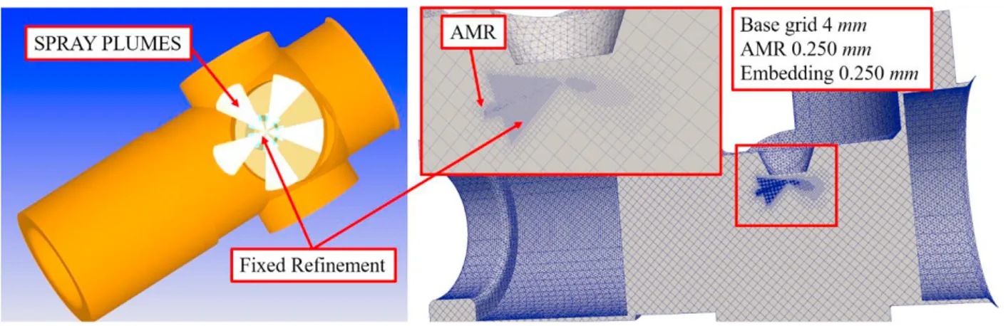
The 3D-CFD simulations have been carried out with CONVERGE CFD v2.4.14 [18] on the Marconi Cluster at the CINECA facility [19]. The multi-hole liquid spray has been modeled using an Eulerian-Lagrangian approach. The computational domain has been carefully represented in the 3D model (Figure1-left) and Adaptive Mesh Refinement together with Fixed Refinement strategies have been used to provide high accuracy when required by the numerical simulation. Grid size setup has been selected according to [20] (Figure 1-right).
Information about the energizing time, total injected mass and injection pressure have been carefully set in order to match the experiments. However, details such as the mass-flow rate profile or the actual injection time were not available and have been discussed and studied for accurate calibration.
More in details, for the mass-flow rate, the tool developed at the University of Valencia by the Internal Combustion Engine group [21] has been used in order to set a reasonable rate profile of the injection process. Moreover, according
at a sample rate of 20 kHz and a 308 × 304 pixel resolution. Using the described experimental facility, it is possible to run experiments addressed to measuring the spray penetration with different values of injection duration, rail pressure, pressure and temperature into the constant-volume chamber and dwell in case of two consecutive injections. Once captured the spray images, they were processed using LabView software. The first step of the post-processing phase was the images conversion in black (chamber background) and white (spray). In order to increase the contrast between the spray and the chamber background, the spray was exposed to an external light source. The light reflections caused by the internal surfaces and edges of the constant-volume chamber and injector tip were mitigated sticking a black adhesive fabric layer type "mock velvet" on the walls inside the chamber. Instead, the injector tip was masked with the help of the software during the images processing phase, using masks and filters with proper thresholds, as it was not possible to apply the black layer on the tip. Moreover, in order to avoid fogging phenomena from residual drops of the injected fuel, the chamber was frequently washed with continuous fresh inert gas. Then, an automatic procedure was implemented, so that the penetration of each of the five sprays (i.e. the length of the segment joining the tip of the white zone associated to each spray to its nozzle exit) was calculated. Particular care was addressed to the definition of the threshold value for discriminating the presence or absence of the spray. In fact, high threshold values led to a spray morphology similar to the real one, but with the risk of observing a spray splitting or the narrowing of thin areas, like the one corresponding to injector’s tip. On the contrary, lower threshold values generated a more voluminous spray, giving as result a possible merging of different sprays close to the tip area. The images so captured by the camera show the spray projection on the plane orthogonal to the injector axis. Therefore, in order to obtain the real penetration, the penetration estimated through the images post-processing were divided by the sine of half the included angle, 71°. The last post-processing phase consisted in an average operation applied to the penetration of each spray for each acquired image. The penetration so obtained was therefore the average penetration associated to the injector given the setting values for injection pressure, duration, chamber pressure and temperature. More details about the post-processing of the spray images are reported in [17].
3. Numerical Approach
The 3D-CFD simulations have been carried out with CONVERGE CFD v2.4.14 [18] on the Marconi Cluster at the CINECA facility [19]. The multi-hole liquid spray has been modeled using an Eulerian-Lagrangian approach. The computational domain has been carefully represented in the 3D model (Figure1-left) and Adaptive Mesh Refinement together with Fixed Refinement strategies have been used to provide high accuracy when required by the numerical simulation. Grid size setup has been selected according to [20] (Figure 1-right).
Information about the energizing time, total injected mass and injection pressure have been carefully set in order to match the experiments. However, details such as the mass-flow rate profile or the actual injection time were not available and have been discussed and studied for accurate calibration.
More in details, for the mass-flow rate, the tool developed at the University of Valencia by the Internal Combustion Engine group [21] has been used in order to set a reasonable rate profile of the injection process. Moreover, according
Figure 1 - Sketch of the full geometry (left) - mesh strategy and grid sizes (right)
to different studies [22-23] the real injection time has been increased with respect to the actual energizing time in order to take into account the delay observed by the needle actuation during the transient process, through a sensitivity analysis. The actual injection duration has been increased of about 10% with respect to the voltage signals.
Sensitivity analyses have been performed for the discharge coefficient parameter, as well as for the number of parcels breakup model constants. The calibration has been performed for the fastest injection conditions (setup A - 300 µs) (Table 1) and same setup has been used for the longer injection process (setup B - 450 µs), confirming the robustness of the numerical framework here proposed. Both the experiments were performed ad ambient temperature and 25 bar for the vessel pressure.
Table 1. Sensitivity analysis.
Parameter Signal duration 300 µs – Injection pressure 500 bar – Vessel pressure 25 bar Discharge Coefficient 0.265 0.515 0.765
Number of Parcels per nozzle 285 2850 28500
Break-up model KH-standard KH-modified TAB
4. Discussion of the results
4.1. Effect of the break-up model
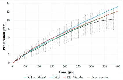
Firstly, the break-up model has been studied for the case setup A. In particular, the standard Kelvin-Helmholtz model has been tested using the nominal value for its time constant and with modified value according to Sun [12]. Moreover, the standard Taylor Analogy Breakup (TAB) model has been tested for the sake of completeness.
Results are reported in Figure 2 in terms of spray penetration.
It is worth noting that both the standard KH and the TAB are not capable of capturing the spray evolution from the beginning of the injection, due to the delayed spray atomization. The modification of the KH model’s time constant allowed for an improvement of the accuracy of the model if compared with the experimental data, differences tend to increase towards the end of the injection process. However, it is worth noting that the small amount of fuel injected may also affect the accuracy of experimental data, especially towards the end of the injection process.
Figure 2 - Spray penetration comparison against experimental data for three different break-up model settings
22 Lorenzo Bartolucci et al. / Energy Procedia 148 (2018) 18–25Author name / Energy Procedia 00 (2018) 000–000 5 4.2. Effect of the number of parcels
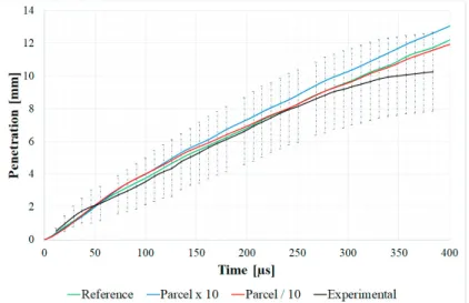
The number of parcels have been changed from a very low value of 285 parcels per nozzle increasing the amount of a factor ten up to the maximum value of 28500 parcels per nozzle. Results of this comparison are reported along with the experimental spray penetration in Figure 3.Results show how an optimum of the total number of parcels
occurs due probably to the low amount of fuel that affects the accuracy of representation of the droplet dynamics as long as a high number is reached.
4.3. Effect of the discharge coefficient
Finally, the effect of the discharge coefficient has been evaluated. Values have been ranged between 0.265 and 0.765, with an intermediate value of 0.515. In fact, as commented already in the literature [24], the discharge coefficient allows describing the area available for the fuel jet taking into account indirectly the link between pressure and momentum. This parameter is key to capture the spray penetration over time: it is evident from the analysis of Figure 4 that values of this parameter in the order of 0.7 may assure levels of penetration coherent with experimental
Figure 3 - Comparison against experimental spray penetration for three different total number of injected parcels
Figure 4 - Comparison against experimental data for three different discharge coefficient
4.2. Effect of the number of parcels
The number of parcels have been changed from a very low value of 285 parcels per nozzle increasing the amount of a factor ten up to the maximum value of 28500 parcels per nozzle. Results of this comparison are reported along with the experimental spray penetration in Figure 3.Results show how an optimum of the total number of parcels
occurs due probably to the low amount of fuel that affects the accuracy of representation of the droplet dynamics as long as a high number is reached.
4.3. Effect of the discharge coefficient
Finally, the effect of the discharge coefficient has been evaluated. Values have been ranged between 0.265 and 0.765, with an intermediate value of 0.515. In fact, as commented already in the literature [24], the discharge coefficient allows describing the area available for the fuel jet taking into account indirectly the link between pressure and momentum. This parameter is key to capture the spray penetration over time: it is evident from the analysis of Figure 4 that values of this parameter in the order of 0.7 may assure levels of penetration coherent with experimental
Figure 3 - Comparison against experimental spray penetration for three different total number of injected parcels
Figure 4 - Comparison against experimental data for three different discharge coefficient
data. On the other hand, also according with literature, the coefficient of discharge at low lift may be lower, indicating a contraction of the area available for the flow [25]. Besides the calibration of the model to represent with proper level of accuracy the experimental results reported here, general conclusions on the calibration of the discharge coefficient would require the internal simulation of the flow into the injector.
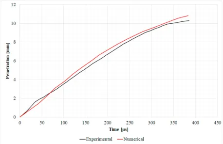
4.4. Final settings adjustment
Based on the final settings for spray, some sensitivity analyses on the turbulent model and diffusivity coefficients have been performed. Keeping the constants’ values within range similar to literature, it has been possible to improve the agreement with the experimental data, especially towards the end of the injection process. More in detail, the time constant of the KH model has been set equal to 1.73 as suggested by O'Rourke and Amsden [26] in order to reduce the time for the breakup process. Moreover, in order to speed up the breakup induced by the RT sub-model the time constant of this model has been set equal to 0.1, while the size constant has been set equal to 0.1. The diffusion is very important to calculate accurately the liquid length penetration. In order to take into account a variation of the slope of the experimental result, the turbulent Schmidt number has been set equal to 0.5 with a value of 0.1045 for the constant Cµ of the k-ε RNG model. Results for this final parameter setup are reported in Figure 5.
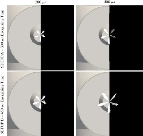
4.5. Comparison of the final set against experimental images.
Once defined the numerical setup, the comparison with the experimental data has been carried out also in terms of direct comparison of the 3D numerical spray plots against experimental images (Figure 6) for both the case setup A and B.
Results show how the general trend and shape of the spray plumes are captured by the numerical simulations even though some discrepancies in the single plumes are evident which can be inferred to the real geometry of the injector which can lead to differences in the nozzle-to-nozzle shots as shown by Torelli et al. in [27], and that can be particularly sensitive to the small amount of fuel injected.
24 Lorenzo Bartolucci et al. / Energy Procedia 148 (2018) 18–25Author name / Energy Procedia 00 (2018) 000–000 7
5. Conclusions
A 3D CFD analysis of the spray injection at low pressure and short energizing timings has been described using the CFD code CONVERGE. A RANS approach has been used to properly set all the parameters and the constants of the numerical framework here proposed. The main results of the analysis can be resumed according to the following points:
A perturbation of the Kelvin-Helmholtz model’s time constant is required in order to capture the primary breakup at low pressure (and hence velocity) operating conditions;
An optimum in the overall number of injected parcels can be found as a compromise between having too low mass per parcels and too high inertia respectively for the higher and lower number of parcels; The discharge coefficient has a dramatic effect on the spray penetration. Despite the small amount of fuel
injected, the value is a relatively high value.
The proposed setup, without any changes, has been found to be accurate for both the energizing timings tested experimentally.
Acknowledgements
The CINECA award under the ISCRA initiative is acknowledged, for the availability of high performance computing resources and support.
Authors would like to acknowledge MSc Student Marco Mazzetta for his contribution to the numerical results presented in the paper.
Authors would also like to acknowledge MSc students Cristian Leucci e Francesco Liquori for their support to the experimental activities presented in the paper.
Figure 6 - Comparison against experimental images of the Lagrangian numerical spray plumes
References
[1] Sibendu Som, Anita I. Ramirez, Douglas E. Longman, Suresh K. Aggarwal, Effect of nozzle orifice geometry on spray, combustion, and emission characteristics under diesel engine conditions, Fuel, Volume 90, Issue 3, 2011, Pages 1267-1276, https://doi.org/10.1016/j.fuel.2010.10.048. [2] S. Som, S.K. Aggarwal, Effects of primary breakup modeling on spray and combustion characteristics of compression ignition engines, Combustion and Flame, Volume 157, Issue 6, 2010, Pages 1179-1193, https://doi.org/10.1016/j.combustflame.2010.02.018.
[3] Seang-wock Lee, Daisuke Tanaka, Jin Kusaka, Yasuhiro Daisho, Effects of diesel fuel characteristics on spray and combustion in a diesel engine, JSAE Review, Volume 23, Issue 4, 2002, Pages 407-414, https://doi.org/10.1016/S0389-4304(02)00221-7.
[4] Su Han Park, Seung Hyun Yoon, Chang Sik Lee, Effects of multiple-injection strategies on overall spray behavior, combustion, and emissions reduction characteristics of biodiesel fuel, Applied Energy, Volume 88, Issue 1, 2011, Pages 88-98, https://doi.org/10.1016/j.apenergy.2010.07.024.
[5] Patterson, M. and Reitz, R., "Modeling the Effects of Fuel Spray Characteristics on Diesel Engine Combustion and Emission," SAE Technical Paper 980131, 1998, https://doi.org/10.4271/980131
[6] Pei Y, Mehl M, Liu W, Lu T, Pitz WJ, Som S. A Multicomponent Blend as a Diesel Fuel Surrogate for Compression Ignition Engine Applications. ASME. J. Eng. Gas Turbines Power. 2015;137(11):111502-111502-9. doi:10.1115/1.4030416.
[7] Som, S. and Longman, D.E. and Luo, Z. and Plomer, M. and Lu, T., Three Dimensional Simulations of Diesel Sprays Using n-Dodecane as a Surrogate, 2011
[8] Dwivedi UU, Carpenter CD, Guerry ES, Polk AC, Krishnan SR, Srinivasan KK. Performance and Emissions Characteristics of Diesel-Ignited Gasoline Dual Fuel Combustion in a Single-Cylinder Research Engine. ASME. J. Eng. Gas Turbines Power. 2014;136(10):101504-101504-10. doi:10.1115/1.4027273.
[9] E. Scott Guerry, Mostafa S. Raihan, Kalyan K. Srinivasan, Sundar R. Krishnan, Aamir Sohail, Injection timing effects on partially premixed diesel–methane dual fuel low temperature combustion, Applied Energy, Volume 162, 2016, Pages 99-113, https://doi.org/10.1016/j.apenergy.2015.10.085.
[10] Kyle A. Hodges, Andrea Aniello, Sundar Rajan Krishnan, Kalyan Kumar Srinivasan, Impact of propane energy fraction on diesel-ignited propane dual fuel low temperature combustion, Fuel, Volume 209, 2017, Pages 769-775, https://doi.org/10.1016/j.fuel.2017.07.096.
[11] F.J. Salvador, J.-V. Romero, M.-D. Roselló, D. Jaramillo, Numerical simulation of primary atomization in diesel spray at low injection pressure, Journal of Computational and Applied Mathematics, Volume 291, 2016, Pages 94-102, https://doi.org/10.1016/j.cam.2015.03.044. [12] Young Sun and Rolf D. Reitz, Modeling Low-Pressure Injections in Diesel HCCI Engines, Proceedings of ILASS Americas, 20th annual conference on liquid atomization and spray systems, 2007
[13] Todd D Fansler and Scott E Parrish “Spray measurement technology: a review”, Measurement Science and Technology, Vol. 26, n. 1. [14] Lyle M. Pickett, Caroline L. Genzale, Julien Manin, Louis-Marie Malbec and Laurent Hermant “Measurement Uncertainty of Liquid
Penetration in Evaporating Diesel Sprays”, Proceedings of ILASS Americas, 23rd Annual Conference on Liquid Atomization and Spray Systems, Ventura, CA, May 2011.
[15] P. Carlucci, D. Laforgia, A. Ficarella, L. Strafella “Improvement of a dual fuel biodiesel-producer gas engine performance acting on biodiesel injection parameters and strategy”, Fuel 209 (2017) 754-768 (DOI: 10.1016/j.fuel.2017.07.100).
[16] Carlucci AP, D’Amico L, De Domenico S, Ficarella A, Santino A, Strafella L, et al. Biodiesel production from Cynara Cardunculus L. and Brassica Carinata A. Braun seeds and their suitability as fuels in compression ignition engines. Ital J Agron 2016;11:47–56. http://dx.doi.org/10.4081/ija.2016.685.
[17] P. Visconti, P. Primiceri, L. Strafella, A. P. Carlucci, A. Ficarella “Morphological analysis of injected sprays of different bio-diesel fuels by using common rail setup controlled by programmable electronic system”, International Journal of Automotive and Mechanical Engineering 14 Issue 1 (2017) 3849-3871 (DOI: 10.15282/ijame.14.1.2017.4.0314) ISSN 2229-8649.
[18] “CONVERGE CFD.” [Online]. Available: https://convergecfd.com/. [19] “https://www.cineca.it/.”
[20] Senecal PK, Pomraning EE, Richards KJ, Som SS. Grid-Convergent Spray Models for Internal Combustion Engine CFD Simulations. ASME. Internal Combustion Engine Division Fall Technical Conference, ASME 2012 Internal Combustion Engine Division Fall Technical Conference doi:10.1115/ICEF2012-92043.
[21] https://www.cmt.upv.es/ecn03.aspx
[22] Allocca, L., Bartolucci, L., Cordiner, S., Lazzaro, M. et al., "ECN Spray G Injector: Assessment of Numerical Modeling Accuracy," SAE Technical Paper 2018-01-0306, 2018.
[23] Juan P. Viera, Raul Payri, Andrew B. Swantek, Daniel J. Duke, Nicolas Sovis, Alan L. Kastengren, Christopher F. Powell, Linking instantaneous rate of injection to X-ray needle lift measurements for a direct-acting piezoelectric injector, Energy Conversion and Management, Volume 112, 2016, Pages 350-358, https://doi.org/10.1016/j.enconman.2016.01.038.
[24]Ganippa, L., Andersson, S., and Chomiak, J., "Transient Measurements of Discharge Coefficients of Diesel Nozzles," SAE Technical Paper 2000-01-2788, 2000, https://doi.org/10.4271/2000-01-2788.
[25] L.-Y. Zhou, S.-F. Dong, H.-F. Cui, X.-W. Wu, F.-Y. Xue, F.-Q. Luo, Measurements and analyses on the transient discharge coefficient of each nozzle hole of multi-hole diesel injector, Sensors and Actuators A: Physical, Volume 244, 2016, Pages 198-205, https://doi.org/10.1016/j.sna.2016.04.017.
[26] O'Rourke, P.J. and Amsden, A.A.,- "The TAB Method for Numerical Calculation of Spray Droplet Breakup"
[27] Torelli, R., Matusik, K., Nelli, K., Kastengren, A. et al., "Evaluation of Shot-to-Shot In-Nozzle Flow Variations in a Heavy-Duty Diesel Injector Using Real Nozzle Geometry," SAE Technical Paper 2018-01-0303, 2018, https://doi.org/10.4271/2018-01-0303.