A
A
l
l
m
m
a
a
M
M
a
a
t
t
e
e
r
r
S
S
t
t
u
u
d
d
i
i
o
o
r
r
u
u
m
m
–
–
U
U
n
n
i
i
v
v
e
e
r
r
s
s
i
i
t
t
à
à
d
d
i
i
B
B
o
o
l
l
o
o
g
g
n
n
a
a
DOTTORATO DI RICERCA
Science for Conservation
Ciclo XXII
Settore scientifico disciplinare di afferenza: CHIM/12
TITOLO TESI
MULTI-POLLUTANTS IMPACT ON MODERN CEMENT
BUILT HERITAGE
Presentata da:
Izabela Joanna Ozga
Coordinatore
Dottorato
Relatori
Prof.
Rocco
Mazzeo
Prof.ssa
Cristina
Sabbioni
Prof. Luciano Morselli
Acknowledgements
This work was carried out under the project “European Ph.D. in Science for Conservation (EPISCON)”, promoted by the European Commission with 6FP EU- Marie Curie EST Action.
I wish to express my appreciation to the coordinator of the EPISCON Project Rocco Mazzeo.
I would like to thank my supervisors, Cristina Sabbioni and Luciano Morselli, for the invaluable support, encouragement, supervision and useful suggestions throughout this research work.
I am indebted to Nadia Ghedini and Alessandra Bonazza from Institute of
Atmospheric Sciences and Climate, ISAC-CNR, Bologna, for their friendship and professional collaboration.
I am grateful to Elena Bernardi from Department of Industrial Chemistry and Materials, University of Bologna, for guidance and valuable advices.
I would also like to convey thanks to Francesca Tittarelli and Orlando Favoni from Department of Materials and Environmental Engineering and Physics, Technical University of Marche, for useful discussions and access to the laboratory facilities.
Index
Introduction 1
1. Impact of multi-pollutants on modern cement built heritage 3
1.1. Cement mortars 5
1.2. Impact of air pollutants on cement mortars 9
1.2.1. The carbonation process 10 1.2.2. The sulphation process 11 1.2.3. The cement - NOx interaction 17 1.2.4. Formation of black crust 18
2. Presentation of the selected sites 21
2.1. Centennial Hall, Wroclaw (Poland) 21
2.2. Chiesa dell'Autostrada del Sole, Florence (Italy) 23
2.3. Casa Galleria Vichi, Florence (Italy) 25
3. Experimental work 27
3.1. Sampling 27
3.1.1. The Centennial Hall – sampling 27 3.1.2. Chiesa dell'Autostrada del Sole - sampling 32 3.1.3. Casa Galleria Vichi - sampling 34
3.2. Analytical techniques 37
3.2.1. Optical Microscopy 37 3.2.2. Scanning Electron Microscopy 37 3.2.3. X-ray Diffractometry 38 3.2.4. Differential and Gravimetric Thermal Analysis 38
3.2.5. Ion Chromatography 39
3.2.6. Carbon Compound Discrimination and Measurements 40 3.2.7. Induce Coupled Plasma-Optical Emission Spectroscopy 42
4. Results and discussion 45
4.1. Experimental data of Centennial Hall 45
4.1.1. Optical Microscope Observations 45 4.1.2. Scanning Electron Microscope Observations 48 4.1.3. X-Ray Diffraction Analysis 51 4.1.4. Differential and Gravimetric Thermal Analysis 53 4.1.5. Ion Chromatography data 55 4.1.6. Carbon Compound Discrimination and Measurement 57 4.1.7. Induce Coupled Plasma-Optical Emission Spectroscopy 59
4.1.8. Concluding remarks 65
4.2. Experimental data of Chiesa dell'Autostrada del Sole 66
4.2.1. Optical Microscope Observations 66 4.2.2. Scanning Electron Microscope Observations 68 4.2.3. Induce Coupled Plasma-Optical Emission Spectroscopy 69
4.2.4. Concluding remarks 72
4.3. Experimental data of Casa Galleria Vichi 73
4.3.1. Optical Microscope Observations 73 4.3.2. Scanning Electron Microscope Observations 75 4.3.3. X-Ray Diffraction Analysis 77 4.3.4. Differential and Gravimetric Thermal Analysis 79 4.3.5. Ion Chromatography data 81 4.3.6. Carbon compound Discrimination and Measurements 83 4.3.7. Induce Coupled Plasma-Optical Emission Spectroscopy 86
4.3.8. Concluding remarks 94
Conclusion 95
Introduction
The rapid industrial and urban development occurred in recent decades has influenced the regional air quality by increasing the emission in the atmosphere of gaseous pollutants and aerosols from combustion processes. It is now well known that air pollution has impact not only on the human health but also accelerates the deterioration of building’s façade, monuments and outdoor statues located in urban areas. The dry and wet deposition of air pollutants is demonstrated to be the most important damage factor in building material deterioration; in particular, aggressive airborne particulate matter has been proved to have a driving role in soiling of monument surfaces. The phenomenon of air multi-pollutants deposition has been extensively studied focusing on natural stones, especially marble and limestone, considering their wide use in the construction of many famous European monuments. The research performed on the deterioration of the built cultural heritage due to atmospheric pollutants indicates that SO2 and particulate matter, primarily from the combustion of fossil fuels, are the most dangerous agents in case of marbles, limestone and dolostones. However, the decrease of SO2 emission from industry and domestic fuel burning in recent years in many parts of Europe and the increase in traffic (raising the atmospheric concentration of nitrogen compounds, ozone and particles) have created a new multi-pollutant situation. Only recently, a special attention has been given to the dark component of aerosols, referred to black carbon (soot), which causes aesthetic impairment (blackening) of the building façade in areas protected from rain run-off. The formation of the so called black crusts effects in increase of material roughness and retention of particulate matter by building surfaces.
Despite many studies dedicated to the environmental damage of cultural heritage, in case of cement mortars, commonly used in the 20th century architecture, the deterioration due to air multi-pollutants impact is still not well explored and requires deeper investigation. The present work centers on cement material-environment interaction, focusing on the investigation of the damage of the 20th century architecture induced by air multi-pollutants. For this purpose three European sites, exposed in different urban areas, have been selected for sampling and analysis of damage layers: Centennial Hall, Wroclaw (Poland), Chiesa dell'Autostrada del Sole, Florence (Italy), Casa Galleria Vichi, Florence (Italy).
Through the analytical studies of the samples collected at the buildings under consideration, the complete characterization of damage layer formed on cementitious monuments was achieved for the first time. The results from experimental work allowed the identification and prioritization of the air pollutants responsible for the surface deterioration considering the location of the buildings under study. The comprehensive diagnosis of damage layer and identification of the anthropogenic pollutants influencing its formation, represents a prerequisite for the sustainable protection and conservation of the modern built cultural heritage. The knowledge achieved during this research will be also useful in the construction sector for investigating the durability of modern building materials.
1. Impact of multi-pollutants on modern cement built heritage
The 20th century architecture, characterized by concrete constructions such as high buildings and gigantic bridges, seems to be indestructible. However, it has now been recognized that many modern buildings undergo rapid deterioration, especially in areas with high concentrations of air pollutants. It is demonstrated that the deposition of gaseous multi-pollutants and aerosols plays a major role in causing the deterioration of monuments and built cultural heritage in European cities.
The deposition of air pollutants (SO2, NOx, O3, aerosols, etc.) on building materials can be divided into two sub-processes: dry and wet deposition: (1) dry deposition by the transport of particulate and gaseous contaminants from the atmosphere onto surfaces in the absence of precipitation (Davidson and Wu, 1989) (2) wet deposition by transfer of trace gases and particles occurring in an aqueous form (rain, fog, snow). Dry deposition is slow and continuous, whereas wet deposition delivers sudden and infrequent pollutants in dilute solution (Morselli et al., 2003). The most studied process, in case of building material deterioration especially marble, limestone, sandstone, is dry- and wet- deposition of SO2, which cause growth of gypsum crystals. The major pathways of acid deposition, for example of SO2, can be summarized as follow: SO2 oxidized mainly by reaction with OH radicals leading to the formation of sulphuric acid (H2SO4), which rapidly nucleate to form aqueous H2SO4 droplets, acting themselves as condensation nuclei as cloud droplets. The aqueous phase formation of H2SO4 proceeds via absorption of SO2 in cloud droplets or moist particles and subsequent oxidation reaction. Finally, the aerosol sulphate and gaseous SO2 are subjected to below cloud scavenging by rainfall, removing a large fraction of atmospheric SO2 by acid precipitation (Steiger, 2003). The dry deposit of atmospheric sulphur components involves the gaseous SO2 and particulate sulphate. The overall rate of dry deposition depends on the material properties such as chemical composition and surface wetness, and the reactivity of the atmospheric trace gas of interest (Steiger, 2003). In order to determine and compare the effects of atmospheric deposition on different building materials (stones and mortars) and the mechanism of degradation that occurs on construction materials, exposure tests were performed by Zappia et al., (1998). For the exposure tests, samples of different stones (Carrara marble, Travertine, Trani and Portland
limestone) and mortars (lime, pozzolan and cement mortars) were exposed for 6, 12 and 24 months in two sites: Milan (as an example of urban site) and Ancona (as an example of maritime site).
The results obtained can be summarized as follows:
1. Sulphation is the main process of degradation that occurs on both stones and mortars specimens.
2. The exposed materials showed different degrees of sulphation (Figure 1.1), highlighted the reactivity to SO2 of stones and mortars exposed. Considering the total sulphur detected on the samples, mortars have been demonstrated to be more reactive than stones. This is mainly due to the micro-structural properties such a porosity, in fact mortars have a higher porosity than stones, and therefore higher potential of interaction with pollutants.
3. Taking into account the exposition to the rain run-off, the highest amount of airborne ion concentrations (sulphate, sulphite, nitrate, nitrite, chloride, fluoride, oxalate) respect to the bulk material, was observed in the areas completely protected.
Figure 1.1. Total sulphur (µg cm-2) measured on stones and mortars exposed for 12 months in Ancona and Milan (Zappia et al., 1998).
The literature contains numerous studies on the environmental degradation of building materials, such as natural stone and brick (Sabbioni, 1995; Riontino, et al., 1998), but very few data are available on the impact of air pollutants on mortars, in particularly cement mortar, which is the sign of the modern architecture. Only in recent years have been published a series of works, which have filled in part this gap.
1.1. Cement mortars
Cement mortars belongs to hydraulic mortars group, characterized by the capacity to set and harden under water.
The first evidence of humans using a form of “hydraulic” mortars, was discovered during the excavation of the underground aqueduct of Megara (500 B.C.), where a reservoir was coated with a pozzolanic mortar. This was a lime based mortar, made with an additive of volcanic ash, which gave to it hydraulic properties. The development of hydraulic mortars and theirs application was observed in ancient Greece; the Greek employed pozzolanic mortar obtained by adding volcanic ash from the Thira or Nisiros islands in Greece or from Dikearchia (Pozzuoli) in the Greek colony in Italy. However, it was the Romans, who improved the use and methods of this type of mortars; they substitute the ordinary sand in lime mortar into sand of volcanic origin from the village Pozzuoli close to Vesuvius. This village gave the name to mortars known as pozzolanic mortar and cement (van Balen et al., 2003, Werynski, 2006). The hydraulic properties of this mortars are principally due to presence in pozzolan of aluminium oxide (alumina) and silicon oxide (silica), that thanks to their amorphous, vitreous state and high specific surface area react with lime and water to form calcium silicates and aluminates hydrates (van Balen et al., 2003). The same effect was achieved by later Romans, using rich in silica and alumina ground fired clay (chamotte) or “cocciopesto” (finely ground bricks or tiles) instead of pozzolana. One of the first important works of Romans is the ancient theatre of Pompeii accommodating 20000 spectators (in 75 BC). Numerous works, which are admirable from both technical and architectural perspective follow, such as Coliseum (82 BC), Pantheon (123 BC) and several water reservoirs, like the one in the city of Nimes in France (150 AD). Worth mentioning is the written text “De architectura Libri Decem” by Marcus Vitruvius Polioin (13 B.C.), giving directions to architects for the preparation of a mortar which sets both in air and in water.
In medieval times there was no development of the art of making hydraulic mortar. In the middle of 1700 's AD, an English engineer John Smeaton discovered the hydraulic reaction during observation that lime mortars with lime, which were produced from the burning of
limestone containing clay (silica and alumina), could set both in the air as well as – more importantly - in water. This observation is considered to be the first essential step for the production of cement in the form in which it is produced today. Similar developments of that period were achieved by L. J. Vicat and Lesage in France.
The fundamental step for the creation of cement in the form it is used today, is attributed to the English engineer Joseph Aspdin, who took out a patent in 1824 for “Portland Cement”, which mixed with water and sand gives Portland cement mortar (often known simply as cement or OPC mortar). This name was given because the colour of hardened cement was very similar to the colour of rocks in Portland.
The Portland cement is one of the most common sorts of cement used to produce mortars and concrete since 20th century. First step in Portland cement production is preparation of clinker, through the heating of blended limestone, clay and marlstone. Clinker (95 %), mainly composed of CaO, SiO2, Al2O3 and Fe2O3, is mixed with calcium sulphate (anhydrite, hemihydrate, dihydrate (2-5 %)) and ground to form the cement powder - Portland cement (Czarnecki et al., 1996, Werynski, 2006). The chemical and mineralogical composition of it is presented in Table 1.1 and Table 1.2.
Table 1.1. Chemical composition of Portland cement (Czarnecki et al., 1996).
Chemical formula Notation Chemical name Mass (%)
CaO C Calcium oxide 62-68
SiO2 S Silicon oxide 18-25
Al2O3 A Aluminium oxide 4-8
Fe2O3 F Ferric oxide 3-4
MgO M Magnesium oxide 0.5-2.5
Na2O+K2O N+K Alkali 0.4-3
SO3 Sulfur trioxide 0.8-3
Table 2.2. Mineralogical composition of Portland cement (Czarnecki et al., 1996).
Mineral Chemical formula Notation Chemical name Mass (%) Alite 3CaO·SiO2 C3S Tricalcium silicate 30-65 Belite 2CaO·SiO2 C2S Dicalcium silicate 15-45 Celite 3CaO·Al2O3 C3A Tricalcium aluminate 5-15 Ferrite 4CaO·Al2O3·Fe2O3 C4AF Tetracalcium aluminoferrite 5-15 Gypsum CaSO4·2H2O Calcium sulfate dihydrate 2-5
The addition of water to the clinker causes the process called cement hydratation, during which in the same time undergo two types of reactions: hydration and hydrolysis. Hydration reactions of typical constitutes of Portland cement (alite, belite, celite, ferrite) are presented in Table 1.3. The most abundant hydration products are calcium silicon hydrate (C-S-H) around 70 % and calcium hydroxide Ca(OH)2 around 20 %. The amount of calcium hydroxide results in highly alkaline (pH between 12.5 and 13) and is responsible for material durability.
Table 1.3. Hydratation reactions of typical constitutes of Portland cement (Werynski, 2006).
Mineral: Hydratation reactions: Comments: Alite 2(3CaO·SiO2) + 6H2O → 3CaO·2SiO2·3H2O +
3Ca(OH)2 + Q*
really fast, cause setting and strength development in the first few weeks Belite 2(2CaO·SiO2) + 5H2O → 3CaO·2SiO2·4H2O +
Ca(OH)2 + Q
slower than of alite, this reaction is responsible for strength growth.
Celite 2(3CaO·Al2O3) + 21H2O → 4CaO·Al2O3·13H2O
+ 2CaO·Al2O3·8H2O + Q the fastest among all hydration reactions Ferrite 4CaO·Al2O3·Fe2O3 + CaSO4 + 16H2O →
Ca4·(AlO3·)2SO4·12H2O + Ca(OH)2 + 2Fe(OH)3
starts quickly as water is added, but then slows down
*
heat
All hydration reactions are exothermal, the biggest amount of heat (Q) is produced in hydration of 3CaO·Al2O3 and the smallest of 3CaO·SiO2 (Werynski, 2006).
The hydration of cement is a complicated process taking into account all reactions between water, different phases of clinker and gypsum, which is added to regulate time of setting. At the beginning of this process, when water is put into cement, big amount of alkalis, calcium ions, sulphates, and smaller amount of silica, iron and aluminium ions go into solution. Gypsum starts to react with 3CaO·Al2O3 in the following reaction:
3CaO·Al2O3 + 3CaSO4·2H2O + 26H2O →3CaO·Al2O3·3CaSO4·32H2O,
causing formation of hexacalcium aluminate trisulfate hydrate called ettringite, which belongs to the minerals group known as AFt phases. Gypsum undergoes to a total
transformation into ettringite in first 24 hours of reaction. Alite begins fast reaction with water producing calcium hydroxide. Ettringite and calcium hydroxide are the first products of cement hydratation. In the first 24 hours basic microstructure form appears, consisting of C-S-H needles and C-S-H leafs playing role of connection among separate cement particles. During further hydratation the density of microstructure rises, hardening increases with decreasing speed (Werynski, 2006).
When the source of sulphate (gypsum) is finished the ettringite subsequently starts to react with 3CaO·Al2O3 in reaction:
3CaO·Al2O3·3CaSO4·32H2O + 3CaO·Al2O3 + 4H2O →3Ca4·(AlO3·)2SO4·12H2O,
producing monosulfate from minerals group called “AFm phases”.
Duration and progress of hydratation process depends on different factors. The most important are chemical and mineralogical composition of cement, water/cement ratio, temperature of hydratation, different supplements adding during or in the beginning of hydratation. It is assumed that 70 % of cement paste volume is composed of hyratation products and around 30 % of pores (Werynski, 2006).
1.2. Impact of air pollutants on cement mortars
The studies dedicated to the concrete construction corrosion are mainly focused on the interaction of the cement components with chlorides and sulphates from ground waters (Petri and Kawalec, 1998), while few works have been performed towards the understanding of the interaction of cement matrix with atmospheric multi-pollutants.
Buildings, especially in urban areas, exposed to acid rain precipitation undergo faster deterioration, which in case of cement materials can be observed by white or yellow efflorescence, micro cracks, surface swelling (Petri and Kawalec, 1998). Deterioration of Portland cement mortar, caused by acid deposition, was investigated by several laboratory and field tests performed in different conditions, summarized in Table 1.4 and 1.5. Laboratory and exposure experiments showed that acid rain dissolves calcium hydroxide, the dissolved amount increase with the increase in the acidity of simulated acid rain solution and the decrease in the flow rate (Okochi et al., 2000). A field exposure experiment, carried out for two years indicated that the carbonation of calcium hydroxide and the formation of other corrosion products, such as chloride, nitrate, and sulphate were limited to the surface of mortar specimens. The neutralization progressed more deeply in mortar specimens sheltered from rainwater than in those washed by rainwater (Okochi et al., 2000; Derry et al., 2001).
Rainwater with high concentration of ions such as SO42-, NO3-, Cl-, dissolves easily calcium hydroxide Ca(OH)2, which is responsible for durability of cement. The typical neutralization reaction of Ca(OH)2 can be presented as following:
2HCl + Ca(OH)2 → 2H2O + CaCl, 2H+ + Cl- + Ca(OH)2 → 2H2O + Ca2+ + 2Cl-.
Salts, which are formed during this process, can be dissolved and washed out by rain water, or penetrate with water to inner part of surface. During this process, pH of concrete decreases and deterioration rises, in case of reinforced concrete, corrosion of the reinforcing steel additionally occurs.
The literature dedicated to modern hydraulic mortars deterioration due to the atmospheric multi-pollutants deposition has indicated the following points as requiring further investigation: CO2/H2CO3 (carbonation), SO2/H2SO4 (sulphation), NOx/HNO3-cement components interaction (Marinoni et al., 2003; van Balen et al., 2003). It is known that the deposition of air pollutants and aerosols on carbonate stone materials, in areas sheltered from rain run-off, causes formation of black damage layer (Bonazza et al., 2005); this phenomenon in case of cementitious material is still not investigated.
1.2.1. The carbonation process
Carbonation process is defined as interaction between CO2 and concrete components. This mechanism is based on absorption of carbon dioxide, which converts calcium hydroxide and also hydrated calcium silicates and aluminates into calcium carbonate, that process is restricted by presence of water and relative humidity 40-70 % (Yates, 2003; Alexander et al., 2007; Pede and Guimareas, 2007). Calcium carbonate appears as white efflorescence on concrete surface and it is easily washed out by rain water. Process of carbonation can be presented in reactions:
Ca(OH)2 + H2O + CO2 → CaCO3 + 2H2O; 10 (C-S-H) + 17CO2 → 17CaCO3 + 10SiO2 + 40 H2O.
The process of carbonation can cause also decomposition of ettringite, which acts as binder in cement paste, into gypsum, calcium carbonate and alumina gel in the following reaction (Nishikawa et al., 1992; Grounds et al., 1988):
3CaO·Al2O3·3CaSO4·32H2O + 3CO2 → 3CaCO3 + 3CaSO4·2H2O + Al2O3·xH2O + (26-x)H2O.
The carbonation reactions result in lowering of the pH and destabilizing all the cement hydration products. The decrease of the pH causes the decrease of the Ca/Si ratio of hydrated calcium silicate. It is assumed that 50 % of the CaO present in C-S-H of non-carbonated paste with pH ranging from 13 to 14, will transform into CaCO3 in carbonated concrete reducing pH to 9 (Chang and Chen, 2006). The lower pH has also impact on
stabilities of ettringite and monosulphate: ettringite become unstable below pH of 10.7, while monosulphate below 11.6 (Gabrisova et al., 1991; Zivica and Bajza, 2001).
The carbonation of concrete depends mainly on environment condition, such as CO2 concentration, relative humidity (RH), ambient temperature and pressure, as well as properties of cement: porosity and permeability, water/cement ratio, hydratation condition, age and moisture content (Zivica and Bajza, 2001).
1.2.2. The sulphation process
Interaction between buildings materials and SO2 is assumed to be one of most important factor in buildings materials deterioration. The investigation by laboratory and field exposure test (Table 1.4 and 1.5), and historical buildings built in OPC, show that sulphation is the most common deterioration process on the cement mortars. According to the studies presented in Tables 1.4 and 1.5, in general, the process of SO2 on cement mortars produces effect similar to the effect of CO2: sulphur dioxide converts components of cement paste into soluble salts, which are subsequently leached away eroding the surface and increasing porosity. The diffusion of SO2 through the exterior layer into the interior of the concrete and subsequently dissolution of SO2 in the pore liquid leads to formation of sulphite acid; than to the formation of calcium sulphurous, and its oxidation under the formation of calcium sulphate or gypsum. Products of this reaction (such as gypsum) have significantly higher volume than the starting calcium compounds, therefore within the pores it causes enormous stresses and then swelling and cracking (Sabbioni et al., 2001; Zivica and Bajza, 2001; Sabbioni et al., 2002).
The interaction between atmospheric SO2 and materials of the buildings is via the well-known processes of dry and wet deposition (acid deposition). The studies performed using micro-chambers to study the effect of dry and wet deposition on the cement mortars (Martinez-Ramirez, 1998), reports that sulphur dioxide in dry forms has little impact on Portland cement mortars. It has been shown that in case of dry deposition SO2, the chemical reaction between the mortar components and the gases increases attending the following order:
The author also shows that the conversion of SO2 to SO4= increases, when the cement/H2O ratio decreases.
The investigation by laboratory and field exposure tests, reported in Tables 1.4 and 1.5, show that sulphation process is restricted by the concentration of SO2, relative humidity and the properties of material, such as Al2O3 content and total porosity (Martinez-Ramirez, 1999; Martinez-Ramirez et al., 2002; van Balen et al., 2003).
The products of sulphation process on the cement mortars due to the atmospheric sulphur components or to the sulphate from the ground waters are gypsum (CaSO4·2H2O), ettringite (3CaO·Al2O3·3CaSO4·32H2O) and thaumasite (CaSiO3·CaSO4·CaCO3·15H2O). Gypsum (CaSO4·2H2O) is the first product formed during the hydraulic mortar–SO2 interaction, it is formed during reaction of SO2 with calcium hydroxide in the following reaction:
Ca(OH)2 +SO2 +
2 1
O2 + H2O → CaSO4·2H2O.
Gypsum is characterized by higher solubility and volume than Ca(OH)2, and its formation effects in loss of strength and durability of cement paste. The problems generated by the formation of gypsum depends on different situations: first, after its formation on the surface, it can be easily washed away from the areas exposed to precipitation, eroding the surface and increased porosity due to its high solubility compared to the compounds of the original materials. On the other hand, the sulphation leads to the formation of black crusts on the surface of low porosity materials (marble and compact limestone) or occurs inside the pores in materials with high porosity, such as mortars and sandstones (Riontino et al., 1998; Sabbioni et al., 1998; Marinoni et al., 2003).
Ettringite is a mineral formed due to the reaction between sulfates, calcium aluminates and water. It can be found in cement materials in three forms: primary ettringite, delayed ettringite formation (DEF) and secondary ettringite. Primary ettringite is a product of hydratation and it is not hazardous (described in Chapter 1.1).
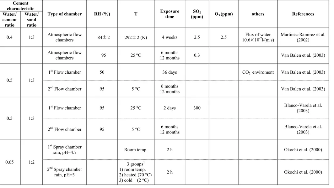
Table 1.4. a Laboratory chamber tests on cement mortars. Cement characteristic Water/ cement ratio Water/ sand ratio
Type of chamber RH (%) T Exposure time SO2
(ppm) O3 (ppm) others References
0.4 1:3 Atmospheric flow chambers 84±2 292±2 (K) 4 weeks 2.5 2.5 10.6Flux of water ×10-7l/(m·s) Martinez-Ramirez et al. (2002)
Atmospheric flow
chambers 95 25°C 12 months 6 months 0.3 Van Balen et al. (2003)
1st Flow chamber 50 36 days CO2 enviroment Van Balen et al. (2003)
0.5 1:3
2nd Flow chamber 95 5 °C 6 months
12 months Van Balen et al. (2003)
1st Flow chamber 95 25 °C 2 days 300 Blanco-Varela et al.
(2003) 0.5 1:3
2nd Flow chamber 95 5 °C 6 months
12 months
Blanco-Varela et al. (2003) 1st Spray chamber
rain, pH=4.7 Room temp. 2 h Okochi et al. (2000)
0.65 1:2 2nd Spray chamber rain, pH=3 3 groups1 1) room temp. 2) heated (70 °C) 3) cold (2 °C) 2 h Okochi et al. (2000)
Table 1.4. b Laboratory chamber tests on cement mortars. Cement characteristic Water/ce ment ratio Water/sa nd ratio
Type of chamber RH (%) T Exposure Time SO2
(ppm) O3 (ppm) others References
0.4 3:1 Spray chamber rain, pH = 4 35 °C2 90 days Martinez-Ramirez and
Thompson (1999)
100 Room temp. 1cycle: (24h in solution /24h drying) Sersale et al. (1998) Spray chamber 1cycle: (120h spraying / 48h drying) Sersale et al. (1998)
1 1st group at room temperature until next exposure
2nd group for 4 hours at room temperature, then heated at 70 °C 4 hours, and again at room temperature until next exposure
3rd cooled about –2 °C for 4 hours and then at room temperature until next exposure
Table 1.5. Field exposure experiments of cement mortars.
Exposure side to rain water: Material Water/cement ratio Water/sand ratio Site Time of exposure
not sheltered sheltered partly completely sheltered References
Portland cement 0.65 1:2 Kanagawa University in Yokohama City,
urban area in Japan. 2 years yes no yes
Okochi et al. (2000)
City centre site: Southwark, London.
Portland Cement 0.8 1:4
Suburban site: Horsted, Chatham, Kent
April – November
in one year yes no yes
Derry et al. (2001)
Modern hydraulic
mortars 1:3
City centre, large industrial area: Milan, Ancona
6 months 12 months
24 months yes yes yes
Zappia et al. (1998)
There has been many studies dedicated to delayed ettringite formation which is associated with damaging sulphate attack. Its formation occurs when primary ettringite it is subjected to temperatures between 70 °C and 90 °C and undergoes decomposition into monosulphate, then, during the temperature drop, monosulphate reacts with water (moisture) and sulphate, and ettringite (DEF) is formed again. This reformation of ettringite causes the new crystal growth inducing stresses in materials and subsequently cracking. The process is limited by moisture conditions and internal sulphate sources (Stark and Bollmann, 2002; Collepardi, 2003; Ekolu et al., 2006 ). The secondary ettringite is formed due to external sulphate sources. However, whilst the formation of secondary ettringite due to sulphate from ground water is well understood, the process due to atmospheric sulphur component is not well investigated. This type of ettringite is produced in reaction between gypsum and calcium aluminates hydrate (van Balen et al., 2003):
3 CaSO4·2H2O + 3CaO·Al2O3·6H2O + 20 H2O → 3CaO·Al2O3·3CaSO4·32H2O.
This reaction is regulated by access to water (relative humidity), temperature, concentration of SO2 and materials properties such as Al2O3 content and porosity. The crystal growth in the voids of cement matrix results in expansion effect (Collepardi, 2003). Thaumasite (calcium silicate carbonate sulphate hydrate) is a third mineral after gypsum and ettringite found as product of sulphate attack in cement modern construction. Naturally, thaumasite occurs mainly in metamorphic rocks, having crystallizes in the hexagonal system and needle-shaped, that is similar to ettringite structure. The formation of thaumasite in cement-based materials depends on the presence of ions, such as carbonate, sulphate and silicate, associated with calcium cations, and is limited by access to water (Crammond, 2002; Romer, 2003; van Balen et al., 2003; Collett et al., 2004; Ma et al., 2006; Bellman and Stark, 2007). The process of its formation can be presented in formula:
CaSO4·2H2O + CaCO3 + CaSiO3·H2O + 12 H2O → CaSiO3·CaSO4·CaCO3·15H2O.
The destructive effect of thaumasite formation consists of the decomposition of C-S-H compounds, which creates “mushy concrete” and decreases the strength of the material.
However, while there has been performed a lot of studies mainly linked to formation of this mineral due to groundwater, this process is still not well understood. The research on the thaumasite form of sulphate attack (TSA) has been carried out by “Thaumasite Expert Group” (TEG) (1999). Through the investigation, the risk factors responsible for thaumasite formation were defined as presence of sulphates ions, ground water, carbonate (in coarse and fine aggregates) and low temperature (<15 ºC). Anyhow, further researches lifted up this theory, showing that among this four factors, sulphate source must be always present (external or internal) and in conditions to penetrate into the cement matrix from outside (i.e. high concentration of SO2 in atmosphere). In fact, the presence of ground or mobile water is not required, the low temperature accelerate thaumasite formation, but it can be also found in warm climate, carbonate can come from external sources not just from aggregates (Sims et al., 2004). It has been also revealed that thaumasite can be formed also during transformation of ettringite (van Balen et al., 2003; Köhler et al., 2006).
1.2.3. The cement - NOx interaction
It is known that in urban areas sulphur dioxide and nitrogen oxides are the most important gases associated with acidity precipitation (Morselli et al., 2008). The effect of NOx on Portland cement is practically not documented. Nitrogen oxides present in atmosphere under suitable conditions can deposit on concrete surface. NO2 or nitric acid are relatively unstable and can easily undergo oxidation. Reaction of NO3 with cement matrix component is analogical with the one of CO2 and SO2. The salts (called calcium nitrate) formed during the reaction:
Ca(OH)2 + 2HNO3 + H2O → Ca(NO3)2·4H2O
are very soluble, therefore no expansive phenomena occurs. Instead, the leaching appears on the attacked layer when NO2 comes in the contact with concrete (Zivica and Bajza, 2001). However, it is very difficult to determine the effect of NOx, which plays also roles as oxidant (for example in sulphation process) and oxidation catalysts (Massey, 1999). There has been performed some tests of cement paste corrosion in acid solution, which has shown the magnitude of the aggressive effect of three acids solution in following order
HNO3 > HCl > H2SO4, anyhow this result are difficult to evaluate in historical building effected by rainwater and acid deposition (Pavlik, 1994; Okochi et al., 2000).
1.2.4. Formation of black crust
The deposition and accumulation of multi-pollutants and products of chemical reactions occurring in material surfaces, in areas protected from rain run-off, leads to formation of the so-called black crust. The formation of the black damage layer results not only in aesthetic impairment (blackening) of the building façade but also causes material loss (Ghedini et al., 2006). The characterization of the black crusts on natural stone has indicated gypsum as main component followed by calcite with embedded airborne particulate matter, including carbonaceous and aluminosilicate particles and also metal particles mainly composed of iron (Del Monte et al., 1981; Sabbioni and Zappia, 1991; Zappia et al., 1993; Ghedini et al., 2000; Bonazza et al., 2005). The carbonaceous particles are responsible for darkening of the surface and, due to heavy metal content, act as catalytic support for the heterogeneous oxidation of SO2 (Benner et al., 1982; Hutchinson et al., 1992; Sabbioni, 1992).
The black damage layer on cement-based mortars is modestly known in monuments and construction sector. The analyses of black crusts from the indoor walls of a concrete tunnel indicated gypsum as the main components with embedded particulate matter produced by fuel combustion. In particular, embedded in the gypsum matrix were found aluminosilacate particles from coal combustion and carbonaceous particles with oil-derived fuels origin (Marinoni et al., 2003).
The studies performed on black crust on the stone monument indicate that sulphur and carbon are the most important elements of anthropogenic origin present in the damage layers on monuments located in urban areas (Sabbioni and Zappia, 1992; Sabbioni et al., 1998; Ghedini et al., 2000).
Carbon in damage layers of monuments in marble and limestone can have different origins: (1) calcium carbonate deriving from underlying material; (2) deposition of atmospheric particles from combustion sources; (3) biological weathering; (4) decay of organic treatment applied in the past ( Zappia et al., 1993). Due to the presence of calcium carbonate in damage layers, the measurement of the total carbon is not sufficient to
quantify the carbon of atmospheric origin, therefore the total carbon (TC) is considered to be composed of two fractions:
TC = CC + NCC,
where CC is the carbonate carbon (originating from the building materials), and NCC is the non carbonate carbon, which in turn is composed of elemental carbon (EC) and organic carbon (OC):
NCC = EC + OC,
both EC and OC are closely related to atmospheric pollutants. The EC is a certain tracer for combustion, being entirely due to particles emitted by combustion processes into atmosphere; in monuments deterioration it causes blackening of the surface (Bonazza et al., 2007). The organic carbon (OC) is linked to a number of different and often simultaneous origins, including the atmospheric deposition of primary and secondary pollutants (Saiz-Jimenez, 1993; Turpin and Huntzicker, 1995; Cachier, 1998), biological weathering (Saiz-Jimenez, 1995); and the decay of protective organic treatments (Rossi Manaresi, 1996).
Few works reported the quantitative measurements of the carbon content in the damage layers formed on the stone monuments (Zappia et al., 1993; Ghedini et al., 2000; Bonazza et al., 2005; Ghedini et al., 2006); in case of cementitious materials used in 20th century architecture, this subject is not been explored.
The first data set on carbon fractions in surface damage layers on European stone monuments has been published by Bonazza et al. (2005). During this research, methodology combining thermal and chemical treatments was applied to quantify OC and EC fractions in damage layers on European monuments. This, in order to determine the role of carbonaceous aerosols in surface blackening, in terms of the amount of anthropogenic carbon in black crust composition. The results obtained demonstrate that OC and EC fractions are always present in the damage layers on monuments. In general the OC fraction predominates over the EC one, which was particularly evident in the damage layers collected from the monument sides exposed directly to air pollution due to
traffic. This work demonstrated also that damage layers are a record of the environmental changes occurring over time at each specific site, with their chemical composition reflecting that of the atmospheric combustion sources. In particular, they act as cumulative markers of the historical sequence of sources producing the atmospheric pollution responsible for their formation (Bonazza et al., 2005).
2. Presentation of the selected sites
The aim of this work is to evaluate the impact of air multi-pollutants on modern built heritage; for this purpose three buildings from 20th century architecture exposed in different urban atmospheres were selected: Centennial Hall (Wroclaw, Poland), Chiesa dell'Autostrada del Sole (Florence, Italy) and Casa Galleria Vichi (Florence, Italy).
2.1. Centennial Hall, Wroclaw (Poland)
The Centennial Hall (Figures 2.1, 2.2, 2.3) is located in the urban area of Wroclaw, situated in one of the most industrialized and polluted regions of Poland, called Silesian Coal Basin. In this area in 1992 was produced 23 % of Poland’s total SO2 emission, though it occupies only 2 % of the country’s area. In the past, Poland was a country having large heavy and power industry based on coal as a primary energy source. Since 1990, due to the Government’s effort through legislative, regulatory and economic means, considerable improvements have been achieved in reducing air pollution in the country’s industrial areas (Nagy et al, 2006). The Centennial Hall is located in close neighbourhood of coal power stations; the closest one is just 5 km away from the monument.
The hall was built in 1913 according to the plans of Max Berg, to commemorate the 100th anniversary of victory over Napoleon in the Liberation Wars of 1813-15. In 2006 it was added to UNESCO’s prestigious list of World Heritage Sites, as one of the most important achievements of 20th century architecture.
Centennial Hall is a landmark in the history of reinforced concrete architecture; it was one of the world's biggest dome-like structure. This is a pioneering construction of modern architecture, which shows an important interchange of influences in the early 20th century, becoming a key reference in the later development of reinforced concrete structures. The building has the form of a symmetrical quatrefoil (Figure 2.3), with an inner diameter of 69 m and a height of 42 m, creating a vast circular central space, with seating for up to 6000 people.
Figure 2.2. Centennial Hall, Wroclaw (Poland).
Figure 2.3. Centennial Hall, Wroclaw (Poland) source:
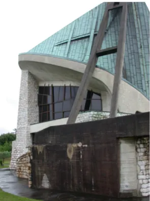
2.2. Chiesa dell'Autostrada del Sole, Florence (Italy)
Chiesa dell'Autostrada del Sole (Church of the Highway of the Sun) is situated West of Florence (Italy), between Autostrada del Sole (Highway of the Sun) and the A11 Firenze-Mare highway. The Autostrada del Sole or Autostrada A1 is the longest Italian motorway which connects Milan with Naples through Bologna, Florence and Rome, and it is considered the “spinal cord” of the country’s road network.
The Chiesa dell'Autostrada del Sole was built between 1960 and 1963 according to plan of architect Giovanni Michelucci with intention to honor the workers who had died constructing Italy's highways, and was also intended for use by people traveling those highways.
The project of the church reflects both modern and traditional church design. The "cross" floor plan and stone facing are meant to induce a traditional sense while the tent-like vertical elements and copper roofing reflect modern design tastes. The church stands 27.5 m high.
Building maintenance is performed in regular cleaning program; last restoration work was performed two years before sampling.
2.3. Casa Galleria Vichi, Florence (Italy)
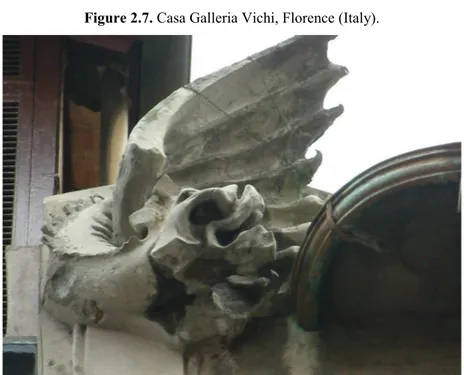
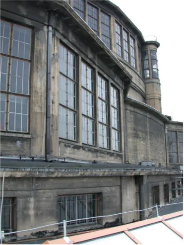
Casa Galleria Vichi (Figures 2.6 and 2.7) is located in the historic centre of Florence (Italy), where traffic is the most significant source of air pollution. The palace is directly exposed to vehicle traffic pollutants emitted from road adjacent.
The Casa Galleria Vichi was designed by architect Giovanni Michelazzi in 1911, commissioned by Argia Marinai Vichi as home and gallery and it still serves this purpose today. The concrete palace was built in the style of art nouveau and is the unique example of liberty style in the centre of Florence. The eccentric narrow façade encloses structural and sculptural fantasy motif composed by a mix of artificial stone, steel and glass. Every floor is characterized by a central stained glass window designed following the typical line curve "a colpo di frusta" cut in horizontal elements. The ground and first floor (Figure 2.6) are utilized for commercial use and are more fanciful ornamented with sculptures and reliefs, for example with the eagle holding the lamp, while upper floors to residential use, are less decorated with pilasters around the central windows. The crown of the façade is decorated with two dragons (Figure 2.8).
Figure 2.7. Casa Galleria Vichi, Florence (Italy).
3. Experimental work
3.1. Sampling
The investigation of the impact of air multipollutants on the 20th century architecture was performed through the laboratory analyses on samples collected from three buildings described in Chapter 2. The sampling sessions were performed taking into account the different levels of the buildings and the protection from rain: sheltered, partly sheltered and exposed areas. Following the analysis criteria, the damage layer was sampled in the form of incoherent deposit for chemical analyses, and in fragments for morphological observation and mineralogical characterization. The samples of damage layer were collected using a brush. In case of coherent crust, strongly attached to the surface, was applied a scalpel to scrape it away, limiting removal of the undamaged material. The fragments were collected using scalpel and hummer taking into account the minimum invasiveness of the operations.
3.1.1. The Centennial Hall – sampling
The samples, in form of damage layer and fragments, were collected taking into account the height from ground level and the protection from rain run-off, on different sides of the Centennial Hall. The plan of the building with sampling points is shown in Figure 3.1. During sampling the dark damage layer appeared in areas protected from rain wash out (Figures 3.2 and 3.3), with maximum thickness in the highest part of the building (Figure 3.4). In some cases the crust was strongly attached to the surface (coherent crust), making it difficult to scrape away. The samples collected with a brief description are listed in Tables 3.1. a and b.
Table 3.1.a.List of samples collected on Centennial Hall, Wroclaw (Poland). Sample Height (m) Side/ sampling area Protection from rain Description
CH1 1.5 North partly sheltered fragment (substrate + damage layer) CH2 1.5 North sheltered grey coherent crust
CH3 1.5 North partly sheltered grey coherent crust
CH4 1.5 South partly sheltered fragment (substrate + damage layer) CH5 1.5 South sheltered grey crust
CH6 1.5 North-East sheltered grey coherent crust
CH7 12 East sheltered fragment (substrate + damage layer) CH8 12 East partly sheltered fragment (substrate + grey damage layer) CH9 12 East partly sheltered grey coherent crust
CH10 12 East sheltered fragment (substrate + grey damage layer) CH11 12 East sheltered fragment (substrate + damage layer) CH12 12 South-East partly sheltered crust from yellow area
CH13 14 South-East partly sheltered grey crust CH14 14 South partly sheltered grey coherent crust CH15 14 East partly sheltered dark crust
CH16 14 North unsheltered coherent crust from yellow area CH17 14 South-East partly sheltered dark coherent crust
CH18 14 North sheltered dark crust
CH19 14 South sheltered fragment (substrate + damage layer) CH20 14 South-East sheltered fragment (substrate + damage layer) CH21 14 East partly sheltered fragment (substrate + damage layer)
Table 3.1.b.List of samples collected on Centennial Hall, Wroclaw (Poland). Sample Height (m) Side/ sampling area Protection from rain Description
CH22 12 South sheltered fragment (substrate + damage layer) from the building on the second floor CH23 12 South sheltered fragment (substrate + damage layer) from the building on the second floor CH24 12 South partly sheltered grey coherent crust from the wall of the building on the second floor CH25 27 East fragment found on the floor
CH26 27 substrate
CH27 27 substrate
CH28 27 West partly sheltered fragment (substrate + damage layer) CH29 27 West partly sheltered fragment (substrate + damage layer) CH30 27 West partly sheltered grey crust
CH31 27 North partly sheltered crust from yellow area CH32 27 South-East partly sheltered crust from yellow area
CH33 27 South-East sheltered fragment (substrate + damage layer) CH34 40 North-East sheltered dark coherent crust
CH35 40 North-East partly sheltered coherent crust from yellow area
CH36 40 North-East sheltered fragment (substrate + dark damage layer) CH37 40 North sheltered fragment (substrate + dark damage layer) CH38 40 North-West sheltered thick dark crust with rough surface CH39 40 East sheltered fragment (substrate + damage layer) CH40 40 East sheltered fragment (substrate + damage layer) CH41 40 North-East sheltered fragment (substrate + damage layer) CH42 12 North West sheltered grey coherent crust
Figure 3.1. Plan of the Centennial Hall (North-West), sampled areas within the red, yellow, green circles.
Figure 3.2. Centennial Hall (Wroclaw), there are observable areas with black crust.
Figure 3.3. Centennial Hall, sampled areas with black crust.
3.1.2. Chiesa dell'Autostrada del Sole - sampling
Samples were collected from the concrete wall on the northern part of Chiesa dell'Autostrada del Sole as it is shown in Figures 3.5, 3.6 and 3.7. This part as well as the whole Church, was restored (cleaned) two years before sampling. Under visual assessment, the damage layer was not observed on the jointing mortars and on the concrete parts of the church. The samples collected in form of fragments for subsequent analysis are listed with short description in Table 3.2.
Table 3.2. Samples collected on the Chiesa dell'Autostrada del Sole (Florence).
Figure 3.5. The concrete wall* in the northern part of the Chiesa dell'Autostrada del Sole (Florence). *The concrete wall appears black because the picture was taken in a rainy day and the wall was wet.
Sample Height
(m) Side/sampling area Protection from rain Description FIC_sub North, concrete wall unsheltered substrate
FIC1 0.5 North, concrete wall unsheltered fragment (substrate + damage layer) FIC2 1.70 North concrete wall unsheltered fragment (substrate + damage layer) FIC3 1.50 North concrete wall unsheltered fragment (substrate + damage layer)
Figure 3.6. Chiesa dell'Autostrada del Sole (Florence), sampled area.
3.1.3. Casa Galleria Vichi - sampling
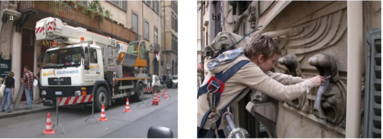
The samples were collected on the facade (South-West) of Casa Galleria Vichi (Florence, Italy) by scalpel or brush, moving on a platform lift as it is shown in Figure 3.8. Sampling was started from above, at a height of 19 m on the left side, then moved to the centre and went to the right side. The same pattern, with horizontal bands, was repeated at other levels as it is presented in Figure 3.9.
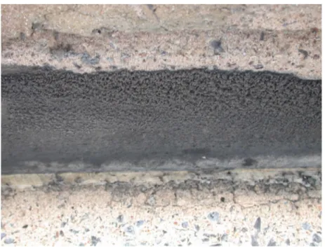
Under visual assessment, the damage layer appeared in areas protected from rain run-off. There were distinguished two types of damage layers; dark coherent crust strongly attached to the surface (Figure 3.10), and incoherent grey deposit with powder consistency (Figure 3.11). In addition fragments with black crust and substrate were collected. The list of the collected samples with their position and brief description is reported in Table 3.3.
Table 3.3. List of samples collected at Casa Galleria Vichi (Florence).
Sample Height (m) Side/ sampling area Protection from rain Description
BOS1 19 dragon of the left sheltered dark coherent crust, rough surface BOS2 19 central part sheltered fragment (substrate + damage layer) BOS3 19 dragon on the right partly sheltered dark coherent crust, probably biological BOS4(2) 19 dragon on the right substrate
BOS5 19 central part sheltered grey incoherent deposit
BOS6 15 shell on the left sheltered dark coherent material, smooth surface BOS7 15 mask on the left substrate
BOS8 15 mask on the left sheltered dark grey incoherent deposit BOS9 15 frame partly sheltered grey incoherent deposit
BOS10 15 mask on the right sheltered dark coherent crust, smooth surface BOS11 15 frame on the right partly sheltered grey incoherent deposit
BOS12 11 frame sheltered grey incoherent deposit BOS13 7 mask on the right sheltered dark incoherent crust
BOS14 5 sculpture on the right partly sheltered dark coherent crust, rough surface BOS1516 5 sculpture on the left partly sheltered dark coherent crust, rough surface
Figure 3.9. Sampling: (a) platform lift, (b) collection of the black crust from area protected from rain ran-off.
Figure 3.10. (a), (b) Sampling points of coherent black crust, Casa Galleria Vichi (Florence).
Figure 3.11. Casa Galleria Vichi. Sampling point, (a) and (b) incoherent grey deposit, easily collected by
brush a b) a) b) b) a)
3.2. Analytical techniques
3.2.1. Optical Microscopy
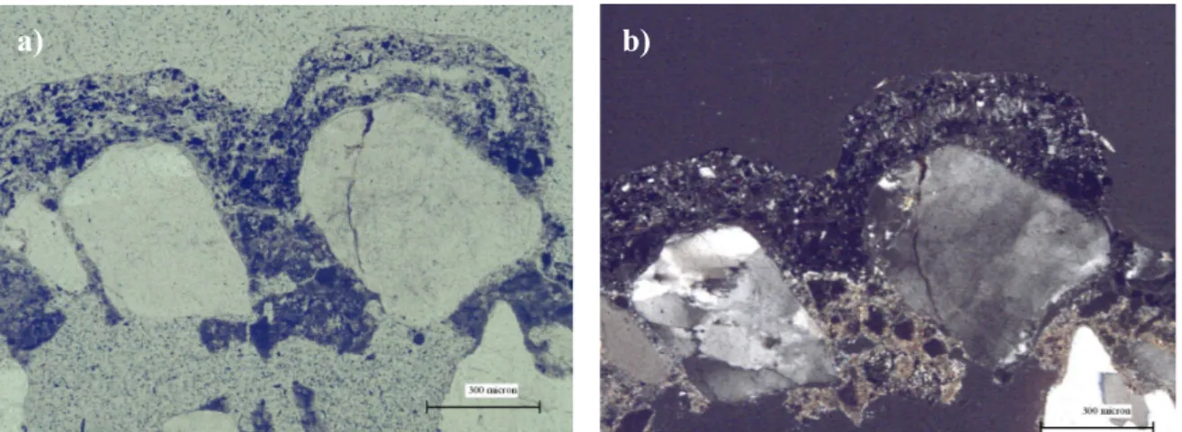
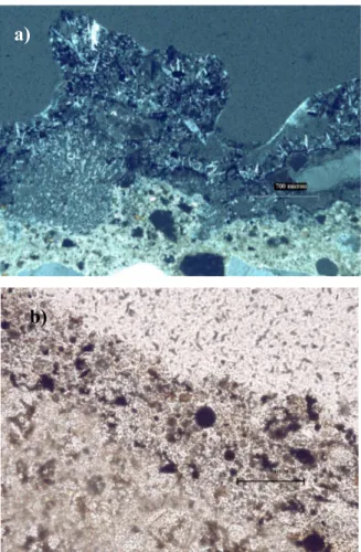
The textural and petrographical features of the samples collected from Centennial Hall, Wroclaw (Poland), Chiesa dell'Autostrada del Sole, Florence (Italy) and Casa Galleria Vichi, Florence (Italy) were observed in transversal thin section using an Olympus BX51 microscopy, equipped with a scanner and the MICROMAX software “Primoplus_32” vers.8.11.02. The aim is the characterisation of the damage layers sampled and of the underlying building material by the mineralogical and petrographical point of view.
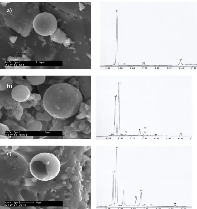
3.2.2. Scanning Electron Microscopy
Scanning electron microscopy (SEM) with energy dispersive X-ray analyser (EDX) is a method generally employed for high-resolution imaging of surfaces of the sample and identification of its elemental chemical composition. The SEM scans the sample surface with a high-energy beam of electrons in a raster scan pattern. The advantages of SEM over optical microscopy include higher magnification (over 100000 times) and greater depth of field up to 100 times that of optical microscopy. The EDX method allows a fast and non-destructive chemical analysis with a spatial resolution in the micrometer regime. It is based on the spectral analysis of the characteristic X-ray radiation emitted from the sample atom upon irradiation by the focussed electron beam of SEM.
The SEM instrument has many application across different industrial sectors; taking into account the high magnification together with localised chemical information, it becomes an useful tool for solving a great deal of common conservation issues, such as soot particle analysis and identification of material defects.
The morphological and elemental characterization of surface damage layers collected from the buildings under study were performed by scanning electron microscope equipped with an energy-dispersive analyser - SEM-EDX Philips XL 20. Samples were mounted on aluminium stubs and coated with a thin layer of graphite to allow surface conductivity. The
application of graphite films is necessary for the correct identification of the emission spectrum of sulphur.
3.2.3. X-ray Diffractometry
X-ray diffractometry (XRD) is a widely used technique to identify crystalline phases, based on their crystal structure. Working principle of XRD is based on the detection of the scattered intensity of a X-ray beam diffracted at angles determined by the spacing of the planes in the crystals and the type and arrangement of the atoms.
XRD is applied in conservation sciences in determining the nature of pigments, deterioration and alteration products both for buildings materials and metal objects.
The X-ray diffractometery in this case was used to identify the main crystalline phases of the damage layers and underlying material collected from the selected buildings. The powdered samples (minimum 3 g) distributed on a Plexiglas stub were analysed by Philips PW 1730 diffractometer equipped with a copper anticathode and a nickel filter. The measurement conditions have a diffraction interval of 2 θ, between 5 ° and 50 °, and a 2 °/minute step at 40 kV voltage and 30 mA current intensity.
This analytical methodology permits the acquisition of qualitative and semiquantitative data on the crystalline phases present in a concentration of at least 3-4 %.
3.2.4. Differential and Gravimetric Thermal Analysis
Thermal analysis techniques determine changes on physical properties and reaction products when a substance is heated under controlled condition. Differential thermal analysis (DTA) monitors changes in thermal properties, either exothermic or endothermic, by detecting the differences in temperature between the sample and inert reference standard. The DTA curve provides data on the transformations that have occurred, such as phase transitions, crystallization, melting and sublimation. Peaks produced during heating are characteristic for specific materials, while the area under the peaks is a measure of the quantity of active material (material, which gives exothermal or endothermal changes in the sample). Thermal gravimetric analysis (TGA) measures the weight loss of material as
function of temperature. The two techniques, DTA and TGA, complement each other to record weight changes and differential thermal analysis curves.
DTA-TGA has long been applied mainly at the study of minerals and polymers and also is commonly used in environmental research.
In this case the DTA-TGA analyses were performed in order to quantify gypsum, carbonates and portlandite in the collected samples by the instrument METTLER TOLEDO TGA/SDTA 851, equipped with a TSO 800GC1 programmable gas switch. The 25-80 mg of powdered sample, placed in 150 microlitre capacity aluminium crucibles, was analysed at constant oxygen flow, temperature ranging between 25-1100 °C and thermal gradient equal to 10 °/min.
3.2.5. Ion Chromatography
Ion chromatography (IC) is a form of liquid chromatography that uses ion-exchange resins to separate atomic or molecular ions based on their interaction with the chromatographic system. Its greatest utility is for analysis of anions, cations and biochemical species such as amino acids and proteins. Most ion-exchange separations are done with pumps and metal columns. Ion chromatography has been widely used to analyse the anionic and cationic components in waters related to acid rain. It is also the most popular and powerful tool for analysis of environmental samples, because of its high accuracy and reliability.
The ion chromatographic analyses are carried out using the Dionex Chromatograph (4500i model), equipped with: conductivity detector (Dionex CD II), injection loop from 5 to 500 µl (inc. 0.010 ID Peek mode), variable wavelength spectrophotometric reader (VDN 2), gradient pump module (GPM-2), micromembrane anion suppressor (Dionex AMMSI), and data acquisition and instrument control (Dionex AL-450 II). As far as sensivity is concerned, the low concentration limit is 0.01 ppm, while for Cl−, NO3− the limit is 0.001 ppm. The instrument is also equipped with an AS14 Ionpac 4mm column for the discrimination and measurement of anions. An Ag 4A-SC Ionpac 4x50mm pre-column and an AS 4A- SC Ionpac 4x250 mm column are required for the measurement of sulphates. The analysis is suitable for measuring the soluble anions. In this case we focused on the following anions: SO4═, NO3–, NO2–, Cl–, Br–, CHO2–, C2H5O2═, C2O4═, in order to understand the acidic deposition on the buildings.
The preparation of the sample and the subsequent analyses includes:
• Prior to analysis, the samples, in form of powder were weighed; the average amount of sample required was ≈ 100 mg. It was put into a glass container, where 50.00 ml of ultra pure (reagent grade) water were added. The container was sealed and put into an ultra sound bath for 30 minutes at a controlled temperature of less than 30 °C.
• The solution obtained was then utilised for the IC anion determination. The amount of ion solution required was 1 ml, which is injected into the instrument by means of a filter of 0.2 µ of porosity.
• A buffer solution Na2CO3/ NaHCO3 (1.8 mM : 1.7 mM) in ultrapure water (reagent grade) employed as eluent.
The amount of every ion must be correlated with the quantity of sample weighed, and expressed as a percentage or in ppm.
3.2.6. Carbon Compound Discrimination and Measurements
The carbon fractions present in the damage layers, collected at the selected sites, were discriminated and measured by flash combustion/gas chromatographic analysis using a conductibility detector (CHNSO EA 1108 FISONS Instruments), according to the methodology published by Ghedini et al. (2006).
The procedure is based on the three distinct stages, each performed on a different part of the same damage layer specimen: 1) total carbon is quantified by burning one part of the bulk sample; 2) non carbonate carbon is obtained by the combustion of a second part of the sample after carbonate decomposition and the complete removal of carbon dioxide; 3) elemental carbon is measured by oxidation of the residue obtained after eliminating the inorganic matrix and organic species by means of a chemical treatment.
The quantity of powdered black crust required for the overall procedure is about 1 g. The procedure is summarized in the following steps:
Step I. Total carbon (TC)
About 10 mg of bulk ground sample, precisely weighed is directly placed into a silver capsule, where it is fully oxidized and quantified by flash combustion/gas chromatographic analysis.
Step II. Non carbonate carbon (NCC)
About 10 mg, exactly weighed, of ground sample is placed in a silver capsule, where it undergoes acidification to remove carbonates by means of maintenance in an atmosphere of HCl concentrate solution until microeffervescence stops. It is then preserved for 12 h in a KOH drier to eliminate CO2, HCl, and H2O before being analyzed by the instrument for non carbonate carbon quantification.
Step III. Carbonate carbon (CC)
Carbonate carbon is calculated as the difference between TC and NCC.
Step IV. Elemental Carbon (EC)
The procedure established for elemental carbon quantification can be presented in the following six stages.
1. An exactly weighed quantity of ground black crust, ranging between 200 mg and 1 g, depending on its EC content and the type of preparation equipment, is placed in an airtight tube, and 2 ml of Na2CO3 saturated solution is added. The tube is then hermetically sealed and heated at 120 °C for 2 h. The cooled sample is centrifuged at 5.000 revs/min for about 10 min and, after liquid-phase removal, is washed with 2 ml of tepid distilled water and is recentrifuged.
2. Subsequently, the residue is treated, under agitation in an open tube, in steps of 20 ml, with a concentrated solution of HCl (37 %), until the effervescence stops; the complete decomposition of carbonates and the removal of CO2 are then obtained by heating the suspension to 40−50 °C. After cooling, the residual sample is centrifuged and rinsed as described above.
The treatment with the Na2CO3 saturated solution (1) leads to the solubilisation of lowest soluble salts (e.g., CaHPO4, SrSO4, CaC2O4) because of the formation of carbonates, which are then removed, together with the carbonates present as mineralogical components of the original sample, using the HCl treatment (2).
3. The residual sample undergoes five alternate digestion steps at 120 °C for 1 h performed with 2 ml HCl 37 % and at 120 °C for 30 min with 2 ml KOH 30 %. Each digestion step is followed by centrifugation and washing with 2 ml of distilled water after the acid digestion and with 2 ml of distilled water, acidified with HCl solution, after the basic one.
The HCl treatments allow the dissolution of basic materials and the decomposition of silicates, while the repeated KOH attacks produce the complete dissolution of the acid
substances, the quartz, and the amorphous silica derived from the HCl action on silicates. The five alternate attacks with HCl and KOH concentrated solutions are indispensable for isolating elemental carbon from particularly complex matrixes.
4. If, after the above steps, the residual sample still reveals the presence of silicates, their complete removal can be obtained by means of a final treatment with NH4F·HF, at 120 °C, until the dissolution of salts, followed by centrifugation and washing with distilled water. 5. For each sample, the liquid phases derived from all treatments, including washing, are collected, mixed, pH adjusted to about 10, added to 25−30 mg of Zn2+ (as ZnCl2), and stirred. The soft jellylike mass resulting from the formation of zinc hydroxide, which contains EC, is isolated by centrifugation, is washed, and is added to the residue of the previous treatment.
6. The sample is finally dried at 180 °C until reaching constant weight, after which it is analyzed by combustion (CHNSO) to evaluate the elemental carbon content.
Step V. Organic carbon (OC)
Organic carbon is then calculated as the difference between NCC and EC.
3.2.7. Induce Coupled Plasma-Optical Emission Spectroscopy
Induced coupled plasma-optical emission spectroscopy is an analytical technique used for elemental chemical analyses. The sample to be analysed must be in liquid form, if solid normally is first dissolved or digested before being fed into the plasma.
The procedure is based on conversion of the molecules of the liquid sample to individual atoms and ions using high temperature ratio frequency induced argon plasma. The sample is introduced into plasma as solution. The analyzed sample is pumped to a nebulizer by peristaltic pump. The purpose of nebulizer is to convert the sample to the fine spray and mix with argon in the spray chamber, where only droplets in a narrow size range are carried into the plasma and instantly excited by the high temperature.
A number of atoms pass into the excited state and, when relax to the ground state, emit radiations characteristic for each element. The emitted radiations are easily detected and the elements identified through an optical spectrometer (in general in the UV, Vis or NIR region). The intensity of the radiation is proportional to the concentration of that element within the solution and so can be used for quantitative purposes.
The concentration of elements in damage layer and underlying material collected on the buildings under study was determined using inductively coupled plasma - optical emission spectrometer (ICP-OES), Circular Optical System CIR.O.S.CCD.
Preparation of the sample for ICP-OES analyses:
• Powdered samples were weighed; the average mass of sample required was ≈ 0.1 g. • The weighted sample was treated with acids mixture: HF (2 ml) + HCl (6 ml) +
HNO3 (2 ml), then the solution was put into the microwave oven in the following conditions: t = 25 min; T = 200 °C; p = 10-15 bar; P = 400 W.
• After heating, to the dissolved samples was added a solution of H2BO3 (22 ml) 4 % and filled with H2O double-distilled till volume of 50 ml.
In order to identify the origin of the elements, the data obtained during ICP-OES analysis were processed with two statistical techniques i.e. student’s t-test and principle components analyses, and the enrichment factors were calculated.
• Student’s t - test
Student’s t-test is a one of the most commonly technique used for testing the hypothesis on the basis of the difference between sample means (William at al., 1992). In this case one tailed t-test was applied to the mean concentrations and the corresponding standard deviations of the elements in substrate and damage layer, to find the elements with a significant positive difference in concentration between damage layer and substrate. The following equation was used:
,
where X1and X2are the mean concentrations of element X in damage layers and substrate respectively, 1 x S and 2 x
S are standard deviations of the two means: damage layers and
substrate, n is number of measured values (n1 in damage layer, n2 in substrate).
Considering the positive differences (X1-X2), if the │tcalculated│> ttable,where ttable is critical
values of t, at level of significance α=0.05 and the degree of freedom N= (n1+n2−2), we can say that the concentration of the element X in the damage layer is significantly (statistically) higher than in the substrate.
2 2 1 2 2 2 2 1 )/ 1 2 ( n S n S X X t x x calculated = − −