Information Engineering Department
University of Pisa
Ph.D. Thesis
“MEM Resonators for RF Applications and
Chemical Sensing”
Curriculum “Micro and nanoelectronic technologies, devices and systems”
XIX CICLO
Tutors: Ph. D. Student:
Prof. A. Nannini Ing. Dario Paci
Acknowledgements
I would like to thank everybody who helped me during these three years of Ph.D., first of all my parents who gave me the necessary support to achieve my goals. I would like especially thank my advisors Andrea Nannini and Francesco Pieri for their helpful suggestion and for the topic they proposed to me to investigate. A great thank you also to people from IMEC, especially Harrie Tilmans and Steve Stoffels, who collaborated with me during my staying at IMEC, as well as to people from PEL-ETHZ, where I spent three very fruitful months.
Then I thank all the people of the Microsystems Laboratory, professors researchers and other Ph.D students, as Antonio, Lucanos and Pietro which shared with me this important experience of my life. Thank also to the master degree students, as Massimo and Andrea, which achieved their thesis with an activity developed at Microsystems Laboratory and which gave in this way also a big contribution to this Ph.D. thesis.
And a final thank you to my beloved girlfriend Giovanna, who stayed always close to me, through all this time, even if sometimes I was too much concentrated on my work or I was even in another country to pursue my Ph.D.
Indeed she was the most important person for me during these last three years and without her no result would be possible or important.
“There are more things in heaven and earth, Horatio, Than are dreamt of in your philosophy.”
Introduction
MEMS (MicroElectroMechanical Systems) offer nowadays several stimulating possibilities to the research of new devices and new architectures for electronics systems. Such devices are composed of mechanical components and transducers, which convert electrical signals (voltages or currents) in mechanical quantities (such as forces, displacements) and vice versa. Their main feature is that they can be fabricated with technologies similar to the ones used to produce integrated circuits, so that MEMS can be fabricated on a chip and in some cases on the same chip together with an electronics system if their fabrication process is fully IC-compatible.
The way MEMS can be produced allows the integration in a system on a package or even in a system on a chip of devices once macroscopic, like many sensor or like mechanical resonators, commonly quartzes, often used in electronics systems as frequency references.
Among MEMS, MEM resonators are particularly attractive: indeed the expression “MEM resonator” includes a lot of different devices, whose operating principle is based on the mechanical resonance of one or more moveable part composing the device.
Several are the proposed potential applications of MEM resonators: they can be used as frequency references in electronic systems or as fundamental components in electronic filters, local oscillators or mixers in RF communication systems. They can be even designed so as to maximize the sensitivity of their resonance frequency to temperature, humidity or the adsorption of a particular kind of molecule, in order to obtain sensors of these respective physical quantities.
MEM resonators for RF applications are especially important because they potentially allow the integration on a single-chip RF transceiver of some of the components, as filters and oscillators, which are currently out-of-chip components. Furthermore, the possibility of integrating a large number of resonators on a single chip leads to the possibility of new architectures for RF transmission systems [1]. In a different field, resonators for chemical sensing can allow new solutions for chemical analysis: a huge number of sensors on a single chip will make the detection of a very large
number of different molecules possible, enabling very complex, simultaneous analyses and making the idea of a “lab on a chip” viable.
Fundamental parameters for a MEM resonator are the resonance frequency and the quality factor. This last parameter measures the frequency selectivity of the filter: a high quality factor means high selectivity in filter architectures and a low phase noise in oscillator architecture.
The goal of this Ph.D. thesis is to give a small, but hopefully important contribution to the research in the field of MEM resonators, and in particular to the design of RF MEM resonators and resonator-based chemical sensors.
The research activity discussed in this thesis starts from the design of MEM resonators for RF applications with resonance frequency in the range 5-50 MHz and high quality factor, intended to be used as filters or as frequency selective element in oscillator. These devices are based on bending polysilicon beams. Among them two innovative devices are presented: the first, namely free-free third-mode resonator with flexural supports, allow theoretically to reach higher resonance frequencies and lower insertion losses than other resonators based on bending beams; the second is a resonator with tuneable resonance frequency.
The design, and the characterization of these devices, will be largely discussed in the following, as well as the results from FEM simulations, which were especially useful to understand the behaviour of these devices when it was different from the expected one. The fabrication of the devices was carried out using THELMA process, provided by STMicroelectronics.
Since the importance of the long-term stability of the resonance frequency of the device if it is used as a frequency reference, the effect of temperature on the resonance frequency of flexural-beam resonators was studied both analytically and by FEM simulations. On the other hand the effect of residual stresses was taken into account, because it can make the device to have a resonance frequency different to the nominal one.
Last but not least, an equivalent circuit for the designed resonators was extracted. Equivalent circuits for MEMS are very important both to allow the simulation of MEMS together with electronics systems with a typical tool for the simulation of electronics circuits (for example Pspice), and to provide a handy and quick synthesis and analysis tool to the system-level designer. Practically equivalent circuits are necessary to facilitate the integration of MEMS with electronic circuits almost as much as the fabrication processes.
The topology of the flexural-beam resonators presented in this thesis was optimized to reach a high resonance frequency. Nonetheless, this kind of resonator can reach only resonance frequency not higher than 100 MHz. To reach higher resonance frequencies, which are needed for several RF applications, it is necessary to choose another kind of MEM resonators, the
so-called bulk-mode resonator, which are based on mechanical structures, such as squares or disks, which are locally compressed or expanded at the resonance. The deformed shape at the resonance of different devices can be dissimilar, but in any case bulk-mode resonators generally allow to obtain a resonance frequency as high as 1 GHz, retaining quality factor higher than in flexural-beam resonators (from 1000 to 100.000 in dependence of the resonance frequency).
Thus, in the framework of a collaboration with the international research centre IMEC (Interuniversity MicroElectronics Centre) of Leuven (Belgium), bulk-mode disk resonators were studied in order to find a way of optimizing their layout. The fundamental task of this optimization was the maximization of the quality factor of the device at the particular resonance frequency given by the specification.
An analysis of the main physical mechanisms determining the quality factor was consequently done. This analysis led to the theoretical models and simulation methods, which will be shown in this thesis and which were essential to optimize the devices design.
While this activity was carried out with respect to MEM resonators for RF application, another research was pursued in the field of MEM resonators for chemical sensing.
In this thesis, the design, fabrication and characterization of an innovative MEM microbalance will be presented. A microbalance is a resonator, which changes its resonance frequency proportionally to the mass of a particular molecule adsorbed by a sensitive layer deposited on the device. Such layer has to be chosen to adsorb maximally one kind of molecule and minimally all the other kind of molecules. A microbalance can be thus used to sense the presence of a particular gas, as well as complex organic molecules, such as proteins or DNA. But it can be even used for other purpose, as for example the measurement of the thickness of a layer deposited on a chip during typical steps of IC fabrication process, such as sputtering or evaporation.
The microbalance which will be presented in this thesis is innovative both because of its mechanical structure and for the actuation.
The resonator is magnetically driven, exploiting the “bias” provided by an external and constant magnetic field, which interacts with an input current flowing in a loop, generating a Lorentz force, which actuates the device. Besides the magnetic field is also used to sense the device movements, which leads to variation of the flow of the magnetic field through another metallic loop, generating an electromotive force as an output signal. Magnetic actuation and sensing are not often used in MEMS, despite their potentiality and only in few cases they are used together.
Finally, a very important feature of the presented device is that it is fabricated with a low-cost CMOS-compatible process. The first steps of the process were carried out using the standard mixed technology BCD6 (including BJT, CMOS and DMOS), provided by STMicroelectronics, while the last steps, including the release of the mechanical structure were accomplished in the Microsystems Laboratory of the Information Engineering Department of the University of Pisa.
1. State of the art of MEM resonators for RF
applications and chemical sensing
1.1 MEM resonators: from the working principle to
the applications
Before any discussion about the topic dealt with in this thesis, it is necessary to define the class of devices addressed: a “MEM resonator” is a micro-electro-mechanical system (MEMS), that is, a machine composed by micrometric transducers, changing electrical signals into mechanical ones and vice versa, and mechanical moveable parts, which can be integrated together on a chip by technologies similar to the ones used to fabricate integrated electronics circuits and sometimes they can be even fabricated on the same chip with an electronic system, if the fabrication processes for MEMS and electronics are compatible. A MEM resonator is usually composed of a mechanical structure (rotor) and one or more transducers, which are used to actuate a force by an electrical signal (input signal), driving consequently the structure into motion, and to transduce its movements in another electrical signal (output signal) proportional to their amplitude (Figure 1). The relation between input electrical signal and force actuated on the rotor depends on the kind of actuation, but can be generally considered as linear at least for small signals, unless the resonator is used as a component in mixers [1] or is characterized employing some particular system of measurements, which requires a non-linear actuation [2]. The same usually holds also for the relation between rotor movements and output signal. If the driving signal is a sinusoid with frequency equal to one of the resonance frequencies of the mechanical structure, the rotor movements are much higher than if the input signal was at a frequency far from any resonance frequencies. As a consequence, being the electrical output signal proportional to the amplitude of rotor movements, also the output signal will be a sinusoid at the same frequency of the input signal and with amplitude higher than at any other frequency.
Generally in a MEM resonator, the mechanical structure and the input transducers are properly designed in order to obtain the highest movements amplitude, when the input signal frequency is equal to one particular
frequency chosen among all the resonance frequencies, while the movements amplitude is minimized for all the other resonance frequencies: in this case, if the resonator is considered as a “black box”, the whole device can be considered as an electrical bandpass filter with central frequency equal to the selected resonance frequency. The same can be obtained also by properly designing the output transducers in order to reduce the output electrical signal amplitude when the device resonates at resonance frequency different from the chosen one. If it is not possible to lessen enough the output signal for all the resonance frequency different from the central frequency of the filter, it can be useful to have a large separation between the selected resonance frequency and all the others, in order to have ideal bandpass behaviour, at least in a certain range of frequencies.
Besides the resonance frequency, the other fundamental parameter, which characterizes a MEM resonator is the frequency selectivity, that is, the ability of cut the input signal at frequencies close but different to the central frequency of the filter.
The selectivity of a resonator is measured by the “quality factor” Q. One of the possible definitions for the quality factor is:
0 3dB f Q B− = (1)
where f0 is the resonance frequency and B-3dB is the 3dB bandwidth, the distance from the resonance frequency at which the output signal is 3dB lower than at the resonance. It is clear that this definition is strictly related to the frequency selectivity concept and that the higher the Q, the higher the selectivity.
Figure 1: Standard structure of a MEM resonator.
Rotor (Resonant mechanical
structure)
Transducer Force Displacement Transducer
Input electrical signal
Output electrical signal
1.1.1 Actuation and sensing mechanisms
The main actuation mechanism used in MEM resonators is based on the electrostatic force: with respect to two conductors (i.e. a capacitor), if they are at a different electric potential they exert a force on each other and if one of the two can move in a direction it can be driven into motion and consequently work as rotor, or be connected to the rotor to actuate it. As an
example, it is possible to consider the parallel plate capacitor in Figure 2a: one of the conductors can move in a rigid way in a direction
parallel to the other one. In this condition, according to the virtual work principle, the actuated force Fe is:
2 0 2 1 1 2 2 e e x x U C H F V V u u d ε ∂ ∂ = = = ∂ ∂ (2)
where Ue is the energy stored in the electric field, ux a infinitesimal displacement in x direction, C the capacitance and V the applied voltage; ε0 is the dielectric constant of the air between the two conductors, H their thickness (in z direction) and d the distance. This kind of electrostatic actuation, constant with the actuation was used often in the oldest resonators [3], but it is not too much efficient.
If the moveable plate is forced to move in direction perpendicular to the other conductor as in Figure 2b, the actuated force is:
(
)
2 0 2 2 1 1 2 2 e e y y y U C HL F V V u u d u ε ∂ ∂ = = = ∂ ∂ − (3)where L is the length along which the electrodes face each other. This time the force is L\d times higher than in the previous case, so that designing long and close electrodes, it is easy to reach values of the force even 100 times higher than in the previous case, applying the same actuation voltage. The drawbacks of the configuration in Figure 2b is that the force depends on the moveable plate displacement uy, introducing a limit to the linearity of equations, which rules the device behaviour. However the displacement amplitude is generally much smaller than the gap between electrodes, so that this electrostatic actuation is generally preferred to the other one, not only for the resonators but also for other MEMS.
In both cases the relation between the input voltage and the actuated force is quadratic, and thus non-linear, so that the signal is generally
superposed to a DC voltage VDC higher enough than the signal Vs, in order to make Eqs. (2) and (3) linear with respect to VS for small value of the signal1.
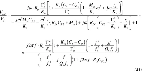
The actuators in Figure 2 can be used also as sensing elements, i.e. to convert the movements of the rotor in an output electrical signal. If a DC bias voltage VDC is applied between the two electrodes and if the moveable plate displacement uy in direction perpendicular to the electrodes is a function of the time (Figure 2b, with VDC = VS), a current I flows in the capacitor:
(
)
(
0)
2 1 2 y y DC DC DC DC y y u u CV C C HL I V V V t t u t d u t ε ∂ ∂ ∂ ∂ ∂ = = = = ∂ ∂ ∂ ∂ − ∂ (4)Considering rotor displacements ux in the other direction (Figure 2a, with VDC = VS) an expression similar for the current can be extracted:
(
)
1 0 2 DC x x DC DC DC x CV C C u H u I V V V t t u t d t ε ∂ ∂ ∂ ∂ ∂ = = = = ∂ ∂ ∂ ∂ ∂ (5)Like the actuation, the sensing mechanism exploiting rotor movements in direction perpendicular to the plates is non-linear but more efficient than the one which converts movements parallel to the electrodes in current, so that it is anyway preferred to this. In general the rotor can also deform, as in the bi-dimensional example in Figure 3. In this case, the forces per unit length, fx along x and fy along y can be defined as:
( )
( )
( )
( )
( )
( )
2 , , , 1 , 2 , , x x y y c x t u x t f x t V f x t c x t u x t ∂ ∂ = ∂ ∂ (6)where c is a capacitance per unit length. While the linear current density j flowing through the capacitor will be, if a DC bias voltage VDC is applied:
( )
( )
,( )
( )
,( )
,( )
( )
,( )
, , , , y x DC DC x y u x t c x t c x t u x t c x t j x t V V t u x t t u x t t ∂ ∂ ∂ ∂ ∂ = = + ∂ ∂ ∂ ∂ ∂ (7) 1 2 ( )2 2 2 DC S DC DC S V = V +V ≈V + V VEqs. (6) and (7) can be easily generalized to the 3D case, defining current density, forces and capacitance per unit area.
Other mechanisms used to actuate MEM resonators or sense their movements exploit magnetic interactions, piezoelectricity, thermal expansion (thermomechanical actuation) and piezoresistivity. These actuation/sensing mechanism are the same used in also all the other MEMS, but in the following they will be discussed with respect to their usage in MEM resonators.
Figure 2: Electrostatic actuation/sensing: a) the moveable plate is forced to move in direction parallel to the plates (x direction); b) the rotor can move only in direction perpendicular to the plates (y direction). The moveable plates are connected to the anchor through a spring.
Figure 3: Electrostatic actuation/sensing of a deformable rotor, leading to a distributed load/current: the moveable electrode is a cantilever, a slender beam clamped at one end.
x y
b)
Fe uy x y Fe uxa)
V V x y fy uy V fx uxFigure 4: Thermomechanical actuation exploiting the bimorphic effect: a cantilever is made of two layers with different coefficient of thermal expansion α1 and α2, so that heating the
cantilever it is possible to bend it.
The magnetic driving [4] generally exploits the Lorentz force acting on a current-carrying wire in a magnetic field, and will be discussed in detail in chapter 4. In this case the input signal is the current flowing in the wire and the relation between driving signal and actuated force is linear. Also a magnetic sensing [6] is possible and in this case the change in magnetic flux through an integrated moving inductance can be exploited. The implementation of magnetic actuation or sensing is complicated by the need of generating a magnetic field and is less efficient than electrostatic when device dimensions scale down. Being necessary to reduce the dimension of devices to reach high resonance frequencies, the magnetic actuation and sensing can be used only for low-frequencies applications.
Piezoelectric actuation and sensing [7] are based on the fact that some particular materials deform if an electric field is applied on them and is directed in a proper direction. They are more efficient than electrostatic, but require the deposition of materials such as AlN (aluminium nitride) or PZT (lead zirconate titanate), which cannot be easily included in fabrication flows compatible with standard electronic processes like the CMOS. This technological complexity generally prevents from implementing piezoelectric actuation and sensing, because the possibility of integration of
x
y
Temperature increase
α
1α
2α
1>
α
2MEMS together with electronics is one of the main advantages of these devices.
The thermal expansion of materials can be exploited to actuate a resonator if it is composed of materials with different coefficients of thermal expansion (CTE) α [8] as the bilayer cantilever in Figure 4: heating the cantilever a compressive stress is exerted on the layers with the highest CTE, while a tensile stress loads the material with the lowest CTE. Thus a stress gradient in transverse direction (y direction in Figure 4) is obtained and it makes the cantilever to bend. This effect is known also as bimorphic effect. The heating of the cantilever can be achieved by driving a current I in heating resistors integrated along the cantilever. The relation between input current and actuated force is non-linear, being non linear the heat q generated by the current (q = RI2 due to the Joule heating). Another important drawback of this actuation is that the highest frequency of the actuated force is limited by the thermal time constant. The time needed for the heat transfer by conduction cuts the higher-frequency excitations. Thus this actuation mechanism was used only for low-frequency resonators (less than 1 MHz) [8].
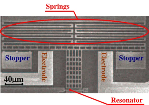
Figure 5: SEM picture of a lumped-parameter resonator taken from [11]. Regions considered as concentrated springs and mass are indicated.
Springs
Finally, the piezoresistivity can be used as a sensing mechanism [4]: resistors made of crystalline materials as silicon, change the value of their resistivity if they are stressed. In this case the resonator output voltage can be extracted by a Wheatstone bridge where one of the resistances is under stress and the others not. Also transistors show piezoresistivity [5]: in this case it is possible to exploit the stress-induced change of electron mobility in the channel.
This sensing mechanism can be easily implemented in CMOS compatible processes, and it is certainly efficient if the resonator or a portion of it is made of crystalline materials where it is possible to fabricate diffused resistors. However piezoresistive sensing is plagued by thermal drifts.
1.1.2 A possible classification of MEM resonators
In the past years many different kinds of resonators have been proposed, so that there are a lot of possible classifications of these devices. One of these involves the way they are actuated and their movements are sensed, so that it is possible for example to talk about electrostatically, magnetically or piezoelectrically actuated resonator. Another classification is connected to the way of model the mechanical structure: it is generally a deformable solid, which can be described as a distributed-parameter system [9], but sometimes it can be considered as a mass-spring-damper system [10], at least for the lowest resonance frequencies. This is possible if the mechanical structure can be separated in two region: one big and rigid whose inertial properties are mainly important and which can be considered as the mass; the other smaller but composed by one ore more flexible structures, which can be considered as pure springs, because their mass can be neglected with respect to the mass of the other region. In this case the resonator can be modelled as lumped-parameter system [10].
The first resonators proposed in literature [3] were lumped-parameter resonators. A more recent example is shown in the SEM picture in Figure 5 [11], where the “mass” and the “springs” are indicated too.
As an example of distributed-parameter resonator, a flexural-beam resonator is shown in Figure 6 [12]. This last device is composed of a beam, that is, a solid with one dimension (length) much higher than the other two (width and thickness), whose deformed shape or mode shape at the resonance is given by a pure bending of the beam.
With lumped-parameter resonator is impossible to reach resonance frequency higher than some hundreds of kHz and it is a limit for a lot of applications, so that generally distributed-parameter resonators were more successful.
Figure 6: SEM picture of a flexural-beam resonator from [12]. Electrodes are indicated as well as the distributed-parameter structure, called “resonator”.
Figure 7: SEM picture of a bulk-mode disk resonator from [13]: if a sinusoidal signal is applied to input electrodes the disk is alternatively compressed and expanded in radial direction.
Among distributed-parameter resonators an important division can be done between flexural resonators and bulk-mode resonators: flexural resonators can be plate or beam as the one in Figure 6, or even systems of more beams connected together, which bend when they resonate, while bulk-mode resonators show resonance bulk-mode shapes defined by a deformation of the volume, or better by an acoustic wave confined inside the volume. Examples of bulk-mode resonators are bars, which are alternatively compressed and expanded in longitudinal direction, as well as disks or square blocks, alternatively compressed and expanded (Figure 7, [13]).
1.1.3 MEM resonators applications
Being MEM resonators basically filters, they can be used in all the applications which include filters or components based on filter. Furthermore, if packaged under vacuum2, they often show a very high quality factor, so that they can be used as frequency-selective elements in oscillator.
Besides, they can be integrated on the same chip with electronics, with advantages in terms of occupied space, with respect to non-integrable solutions. Consequently they are very attractive for all the applications in portable devices, and especially in portable RF communication systems [1] (i.e. GPS, mobile). They can be used as filters or fundamental components in local oscillator, but also to obtain mixers [1], exploiting the intrinsic non-linearity of electrostatic actuation.
They could be useful also for communication systems on satellite, where the miniaturization is very important in order to save weight and the under vacuum package is not needed anymore, because the spatial environment is already at a high level of vacuum.
To be useful for RF applications, MEM resonators have to reach resonance frequency at least higher than 1 MHz, and for some applications even higher than 1 GHz. Given this limits, actuation and sensing in RF MEM resonators are electrostatic, because it do not limit the higher reachable resonance frequency, as magnetic and thermomechanical sensing/actuation do. Electrostatic actuation and sensing are preferred also to piezoelectric, because of its easier technological implementation. RF MEM resonators are generally distributed-parameters resonators because of the impossibility of reaching high resonance frequencies with
2
As shown in the following one of the main mechanism which limits the quality factor of these devices is the energy dissipation due to the interaction between air and resonator surface (air damping).
parameters resonators. The use in RF communication systems is the more attractive application for MEM resonators and the research around this topic is the main subject of this thesis. Thus it will be separately dealt with in the next section. But there are a lot of other possible applications of MEM resonators: they can be used to create frequency reference not only for RF applications but also for all the low-frequency portable applications where a clock is needed.
Besides a MEM resonator can be used as a sensor: a temperature change leads to a change of the resonance frequency of the mechanical structure, as well as the deposition of some material on the surface. Thus using the resonator as a frequency-selective element in an oscillator it is possible to obtain a temperature sensor [14], or by covering the resonator with a proper sensitive layer adsorbing only a particular analyte (the water and thus the humidity, a particular inorganic molecule or a complex organic module as DNA or a protein) [5].
Of course if a temperature sensor is the target, all the molecules adsorbed by the surface introduce an error and, vice versa, if sensing a particular analyte is desired, temperature changes and adsorption of other analytes decrease the sensors selectivity. On the other hand the sensitivity of the resonance frequency to temperature adsorbed mass is only a problem for MEM resonator used as components of filters and oscillators in communication systems: temperature and mass adsorption lead to long-term instability of the central frequency in the first case and of the oscillation frequency in the second case. Limiting the interference introduced by the mass adsorption is thus another reason to package MEM resonator for RF applications under vacuum, while proper materials and topologies [15] have to be chosen in order to reduce the effect of temperature.
The state of the art of chemical sensors based on MEM resonators will be discussed in the 3rd section of this chapter as the second fundamental topic of this thesis. Now the only thing which is interesting to anticipate is that electrostatic actuation and sensing is not obliged as for RF resonators, because it is not necessary that they resonate at high frequency, so that all the actuation and sensing mechanism discussed in this section have been proposed in literature about MEM resonators for chemical sensing.
MEM resonators were proposed also as magnetic sensors: in [16] an external magnetic filed is detected by sensing the movements’ amplitude of a resonator actuated by the Lorentz force exerted on a current-carrying wire. The movements’ amplitude is proportional to both the external magnetic field and the current flowing in the wire. MEM resonators can even work as pressure because of the dependence of their quality factor on the pressure [2].
Finally, MEM resonators were proposed even as components in scanning probe microscope systems [6] and in electrometers [17].
Figure 8: Typical cross-section of an FBAR [21].
Figure 9: Range of use of MEM resonators, quartzes, SAW and FBAR for RF applications.
1.2 MEM resonators in RF communication systems
MEM resonators are very attractive for RF communications, basically because they can be integrated on chip. This advantage is very important especially if their use in filters and oscillators is considered: nowadays bulky and non-integrable devices as quartz and SAW filters are commonly used to obtain filters and oscillators at frequencies below 1 GHz.
100 MHz 1 GHz 10 MHz
Quartzes SAW FBAR
MEM Resonators Flexural-beam resonators Bulk mode resonators 10 GHz
A quartz filter is simply a portion of piezoelectric material such as PZT, with two electrodes attached to two sides of the device. The piezoelectric effect is used to drive into vibration the quartz crystal, by applying an external voltage signal between the two electrodes. But quartz vibrations amplitude influences the current flowing in the device, so that the impedance of the quartz is minimum when the input voltage frequency is equal to the resonance frequency of the quartz and is very high when the input signal frequency is far from the resonance frequency. Practically quartz can be modelled as a series RLC circuit. These devices are very huge and cannot be integrated, but they have very good performance from some hundreds of kHz to 100 MHz: in this range they show very high quality factors and small insertion losses, which are defined as the ratio in dB between the voltages at the output and at the input terminals/ports of a filer at the central frequency, when the output terminal/port is loaded with a standard impedance (generally a 50 Ω resistance). Besides they show also a small sensitivity to the temperature, long-term stability of the resonance frequency and slow aging [18]. If having low insertion losses is very important for a filter, because they quantify the attenuation introduced by the device, an high quality factor is very important for a filter used as frequency-selective element in an oscillator, because an high quality factor reduces the phase noise [19], that is, the short-term variations of the frequency of the output signal from the oscillator, so that an high quality factor of the frequency-selective filter increases the oscillator short-term stability.
SAW (Surface acoustic wave) filters are made of piezoelectric materials as quartz filters, but instead of exploiting a bulk resonance in these filters the wave is confined to the surface. Except for this difference the working principle is the same. They are smaller than quartz filters but cannot be integrated on the same chip with the other electronic components of a communication system, because of the substrate needed to fabricate it (generally LiTaO3 o LiNbO3), which is not compatible with fabrication process for electronics. They are generally used for applications between 100 MHz and 1 GHz and consequently they are especially suitable to be employed as intermediate frequency (IF) filters. Their performance is very good with respect to the quality factor and the long-term stability but worse than quartz performance with respect to the insertion losses [18].
Another class of devices have been recently proposed as fundamental components for RF filter and oscillators: they are called FBAR (Field Bulk Acoustic Resonators). They can work at frequencies from 600 MHz to 10 GHz, but their performance with respect to the quality factor and the insertion losses are excellent especially in the range between 1 GHz and 10 GHz, so that Agilent include them in its commercial duplexers [20]. FBAR can be considered as a sort of integrated quartz filters [21]: they are
generally made of a piezoelectric layer (typically AlN) deposited on a bottom electrode, which lies on some layers of different materials (Figure 8), working as a “distributed reflector”: choosing properly the acoustic impedance and the thickness of each layer in the reflector it is possible to confine the acoustic wave inside the piezoelectric layer; on the other side the same target is automatically obtain because the piezoelectric layer is interfaced with the air, apart from the small region where the second electrode is applied. The resonance frequency increases if the thickness of the piezoelectric layer decreases, and cannot be lower than 600 MHz because too thick piezoelectric layer are required to reach this frequency, leading to a too complex process. Unlike quartz and SAW filters, FBAR are IC (integrated circuits) compatible and it is a very important advantage.
RF MEM resonators have to be compared to SAW and Quartz filters because the highest resonance frequency MEM resonators can reach nowadays is 1.5 GHz [22], even if one of the research issues for RF MEM resonators is increasing the highest resonance frequency, in order to enlarge the range of applications for these devices. Figure 9 summarizes the range of frequencies where each device can be used.
The quality factor of MEM resonators is generally very high and sometimes comparable with quartzes quality factor [23], but their main advantage is the possibility of being integrated on the same chip with the electronics of the communication system. This leads to more compact RF receivers and transmitters for portable applications and to a reduction of parasitic elements introduced by the off chip connection, resulting in smaller power dissipation [1]. But the small dimensions of MEM resonators and the possibility of integrating filters and local oscillators with the other electronic components can lead also to revolutionary architectures for communication systems, as suggested by C.T.-C. Nguyen in [1]. For example the possibility of having a large quantity of filter integrated in a small space allows to design a bank of filters with different central frequencies and high quality factor, which can be used to select the channel just after the antenna and before the LNA (Low Noise Amplifier), obtaining the architecture represented in Figure 10 for an RF receiver with SSB (Single Side Band) demodulator. This bank of selectable filters is a very efficient implementation of an accordable filter with high quality factor, which would be very useful for the first selection of the channel, because it would reduce the complexity of the LNA: in such a way, indeed, the other channels are much more attenuated than if a classical electronic accordable filter is used, so that the specification of linearity for the LNA can be less strictly (this specification being generally due to the need of decreasing the effect of cross-channel interference). Furthermore also noise specification can be
released because the input noise is largely cut owing to the high selectivity of MEM filters.
In the receiver in Figure 10 the selection among one of filters in the bank is done with MEM integrated switches. Besides, also the mixer is replaced with a MEM resonator-based device. It is interesting to consider that a single resonator can have at the same time the function of multiplier and intermediate frequency filter: if the actuation is electrostatic and if a sinusoidal voltage at different frequency is added to the input signal, according to Eqs. (2) to (3) and (6) the quadratic non-linearity of the resonator produces a component of the force equal to the product of the local oscillation and the signal, while the mechanical structure selects the force frequency components around the resonance frequency.
A MEM resonator-based mixer has the great advantage to be a passive element: its power consumption is much lower than the one of the mixers based on active components, which is generally used in RF transmission systems.
MEM resonators can be used to obtain not only high selectivity filers but also relatively large bandwidth filers with high stopband rejections: this can be obtained by coupling two or more resonators with a mechanical element such as a soft beam [24] (Figure 11), or by an electrical coupling element, such as a capacitor [25]. In such a way, if designed properly, the overall resonator has two or more very close resonance frequencies, so that the bandwidth is increased with respect to the case of a single-resonator filter, even if a ripple in the passband is introduced (Figure 11). The high quality factor of each resonator assures a great stopband rejection in multi-resonator filters.
Thus MEM resonators use for RF applications is very attractive owing to the high quality factor, the possibility of large scale integration and the large amount of different devices which can be replaced by a MEM resonator-based counterpart.
But, apart from the quality factor, the performance indicators of RF MEM resonator are generally worse than quartz and SAW filters: the insertion losses are higher and the long-term stability is less than quartz, because of the dependence of resonance frequency on temperature, humidity and mass adsorption and desorption of the resonator surfaces. The problems related to humidity and mass adsorption/desorption can be solved by packaging under vacuum the resonator [26], while with respect to temperature the problem is more complicated as shown in chapter 2.
The biggest problem is connected to the insertion losses. In resonators with electrostatic driving and sensing the insertion losses can be reduced increasing the electromechanical coupling, that is, the actuated force when a unitary input voltage is applied and the output current per unitary
displacement. According to Eqs. from (2) to (7), the easiest way to achieve a higher electromechanical coupling is to increase the bias DC voltage applied between the rotor and both input and output electrodes. But to obtain acceptable insertion losses, many authors ([23],[24]) proposed bias voltage from 10 V to 100 V, which are too high for portable communications systems, usually working with bias voltages below 5 V. Charge pumps circuits, even MEMS-based [27], were proposed to solve the problem, but even considering this possibility the bias voltage cannot off course reach value as high as 100 V. Another way to increase the electromechanical coupling is to optimize the electrodes and the mechanical structure or select the better resonance modes. This strategy can lead to a reduction of both bias voltage and insertion losses and is the strategy developed also in this thesis and in the author’s master thesis [18] as discussed in the chapter 2.
Figure 10: Innovative architecture for an RF receiver for SSB modulated signal, presented in [1]. The components replaced with MEMS are in grey.
Figure 11: Schematic representation of the two resonance modes for a two-resonator filter and of the expected frequency response (from [24]). The resonator is composed of two flexural-beam resonators connected by a coupling beam: on the first resonance mode the two beams move symmetrically, on the second one anti-symmetrically.
Coupling
beam
Finally, the insertion losses can be reduced also increasing the quality factor Q: the output current at the resonance is proportional to Q if the resonator can be represented as a second order system, as it is generally reasonable ([9],[10]). This is a further reason to maximize the quality factor, besides its importance to have high-selective resonator-based filters, multi-resonator filters with high stopband rejection and multi-resonator-based oscillator with low phase noise (high short-term stability). For all this reasons the maximization of quality factor was the main issue of the work about modelling and design of disk resonators, which is discussed in chapter 3.
A parameter strictly connected to the insertion losses is the motional resistance, which is the electrical resistance the resonator can be consider equivalent to at the resonance.
Summarizing, in the research about electrostatically driven RF MEM resonators, the main open issues are, in order of importance:
I. Reducing the insertion/losses (motional resistance), without increasing the bias voltage
II. Increasing the quality factor
III. Increasing the maximum resonance frequency which can be obtained
IV. Increasing the long-term stability of the resonance frequency (temperature effect)
Issues I, II and III were considered in the design of beam flexural resonators presented chapter 2 of this thesis as well as in the optimization of the design of bulk-mode disk resonators discussed in chapter 3. With respect to long-term stability (point IV) an estimation of the sensitivity to temperature of resonance frequency was done only for the flexural-beam resonators.
In the following some solutions presented in literature to solve especially problem I, II and IV are presented. The mechanical structures are generally made of single-crystal Silicon, Polysilicon or Poly Silicon-Germanium (SiGe), a promising structural material for CMOS-compatible process to fabricate MEMS [28]. Recently diamond and Silicon Carbide (SiC) resonators were as well proposed in order to reach high resonance frequencies through the high Young’s modulus of these materials ([11],[22],[29]).
1.2.1 Flexural resonators
Because of the reasons already discussed (resonance frequencies needed and technological complexity) the large majority of RF MEM resonators have an electrostatic actuation and sensing, apart few cases with piezoelectric actuation and/or sensing [30]. Also the RF resonators cited from literature in the following, as well as the RF devices developed in this thesis, have electrostatic sensing and actuation, thus starting from this point all the RF MEM resonator considered in this thesis, will have electrostatic actuation and the sensing.
Besides, being the resonance frequencies achievable with lumped-parameter resonators well below 1 MHZ, the RF MEM resonators are always distributed parameters systems and they are divided in flexural resonators and in bulk-mode resonators, as already said.
Flexural-beam resonators were the earliest distributed-parameter resonators proposed and among them clamped-clamped beam resonators were the first: the resonant mechanical structure is a beam anchored at both the ends, where beam cross section cannot move or rotate, which means that the ends are both clamped (Figure 6). It is a very easy structure composed by only one beam, and among all the resonators composed of only one beam it is the one which has the higher resonance frequency, if the comparison is done among beams with the same length and cross-section. For example if compared with a cantilever resonator, which is a beam clamped at one end and free at the other (as the structure in Figure 3), the resonance frequency of the fundamental mode of clamped-clamped beam is about six times higher than the first resonance frequency of a cantilever with the same lengths and cross-section. This relation is strictly dependent on the different boundary conditions and can be verified using the formulas in [31].
Like every flexural resonator, clamped-clamped beams can be laterally actuated, as the one in Figure 6 [12], when resonator and electrodes lies on the same plane parallel on the substrate, or they can be vertically actuated by an electrode lying on the substrate beneath the beam [1], as the resonator in Figure 12. In the first case the beam bends in direction parallel to the substrate, while in the second case in direction perpendicular to the substrate.
Clamped-clamped beam resonators have a significant quality factor (some thousands), when they work in vacuum and their resonance frequency is less than 15 MHz ([12],[32]). But their quality factor dramatically decreases increasing the resonance frequency [32], so that for higher frequencies clamped-clamped resonators are practically useless. Thus a more complex device, the so-called free-free beam resonator, was proposed: this architecture enhances the quality factor (and thus it also reduces insertion losses) and allows to reach resonance frequencies as high as 90 MHz,
retaining a quality factor more than 20 times higher than a clamped-clamped beam working at the same frequency [33]. A SEM picture of a free-free resonator is presented as Figure 13a.
Figure 12: Schematic representation of a one-port clamped-clamped beam resonator actuated by an electrode lying on the substrate. The figure is taken by [1].
Figure 13: Free-free resonator with torsional supports from [33]: a) SEM picture; b) schematic structure.
a)
In order to understand how the free-free design can improve the quality factor with respect to clamped-clamped beam resonators, it is necessary to discuss shortly the physical mechanisms which limit a resonator quality factor. An expression alternative to (1) for the quality factor Q is:
2 imm L W Q W π = ∆ (8)
where Wimm is the energy stored in the resonator at the resonance and ∆WL, the energy lost per cycle. Thus the quality factor can be extracted by measurement of the frequency response, using Eq. (1), but it can be also estimated from (8), the only thing needed is to find the energy losses or damping mechanisms. In Figure 14 the three main energy losses are represented for a clamped-clamped beam resonator:
a. The surface losses, due (at atmospheric pressure) mainly to the air damping, that is, to the collisions of the air molecules at the resonator surfaces.
b. The intrinsic losses, due to internal friction and vibration-induced heat generation (thermoelasticity). They are localized inside the material and are strictly connected to material properties.
c. The anchor losses, due to interaction between the resonator and the substrate: because of resonators movements a propagating acoustic wave is driven in the substrate at the resonance and the amount of energy stored in the wave is lost, unless it is reflected back by some material discontinuity in the substrate.
The discussion, held in the last years by academics, about the estimation the quality factor in MEM resonators will be detailed later in this chapter, because it was very important for this Ph.D. thesis, whose aim is also to give a small contribution to this subject (see chapter 3). At this point the only important aspect of the problem is that by the dependence of quality factor on the pressure ([2],[32]), it can be demonstrated that the air damping is the higher loss, and thus limits the quality factor at atmospheric pressure. But both to increase the quality factor and to improve the long-term stability of the resonance frequency, resonators has to work in vacuum and in this case the internal losses are always too small to explain the measured quality factor ([18],[36]). Besides in many cases a smaller quality factor was measured increasing the anchor size [37], so that it was concluded by many
authors that anchor losses cause the main energy dissipation in vacuum. In chapter 3 it will be shown that this dependence between anchor size and quality factor is not always true. It holds, however, in the aforementioned cases [37], so that the observation can support the thesis of the centrality of the anchor losses.
To reduce anchor losses and thus increase quality factor, in [33] was proposed an architecture where the beam driven by the input electrode (or main beam) is minimally coupled with the anchor, so that the energy fed by the input signal is maximally confined inside the beam and does not flow
into the substrate through the anchors. This condition is obtained (Figure 13b) by connecting the main beam to the anchors through two other
beams namely supports. The main beam has ‘free’ ends, so that its resonance frequencies can be found solving the problem for a free-free beam (from this come the device name). Supports minimally affect the principal beam mode shape at the resonance, if they are connected at the nodes of the deformed shape of the main at the resonance. The nodes are points which do not move, but around which the beam cross-section is free to rotate. Thus the supports must also not exert any bending moment on the main beam. This can be obtained by considering the beams as mechanical lines of transmission and choosing the supports length in order to obtain a λ/4 adaptation, with a perfect analogy with the λ/4 adaptation usually done in electric transmission lines: the supports when the main beam bends (in z direction according to Figure 13b), are twisted, so that they behave as torsional support and in this case the dynamic equations relating the torsional moment and the derivative of the twisting angle with respect to the time have exactly the same form of the equations relating voltage and current in electric transmission lines, if the moment is replaced by the voltage, the derivative of the angle with respect to the time by the current and the velocity of the torsional acoustic wave by the light velocity.
This λ/4 adaptation leads to the possibility to obtain MEM resonator with Q about 8000 till about 90 MHz, achieving a great improvement with respect to clamped-clamped resonators.
With respect to the maximum achievable resonance frequency, the free-free beam resonance frequencies are equal to the one of a clamped-clamped beam, so that concerning this point the two solutions are practically equivalent. The only small disadvantage of free-free beam is that it occupies a slightly larger surface of the chip, because of the supports.
Another possible architecture is anyway presented by Nguyen for a free-free resonator (Figure 15). This time the resonator is laterally driven and consequently also the supports bend because the free-free beam bends in a direction parallel to the substrate.
Figure 14: Damping source limiting the quality factor in a MEM resonator, shown in the schematic longitudinal cross-section of a vertically actuated clamped-clamped beam resonator.
Figure 15: 3D sketch of the free-free resonator with flexural supports presented in [38].
Also in this case the supports are connected with the main beam at its nodal points and a sort of λ/4 adaptation is done, even if dynamic equations for a bending beam are not equivalent to equations for an electrical transmission line, and thus the analogy is less rigorous than in the case of free-free resonator with torsional supports. The adaptation anyway works, leading to quality factor around 10000 at 10 MHz [38].
The problem of supports adaptation in a free-free resonator with flexural supports will be detailed in chapter 2, where structures similar to the one in Figure 15 will be presented.
In [33] and [38] are presented resonators where the free-free beam resonates on its first resonance mode; designing resonators with free-free beam resonating on higher resonance modes is a way to reach higher resonance frequencies and lower motional resistances with flexural-beam
Internal losses
Anchor losses
Substrate
Air Damping Driving Electroderesonators. Nguyen did it for free-free resonators with torsional supports [39], while in the author’s master thesis, from which these Ph.D. research activities start, a free-free resonator resonating on the third resonance mode with flexural support is presented [18] almost at the same time as the device in [39].
To complete the state of the art of flexural-beam resonator it is mandatory also to introduce another possibility of MEM resonators: their resonance frequency can be varied changing the bias DC voltage applied between rotor and electrodes and thus a MEM resonator can be an accordable filter. This effect is well known in literature ([38],[40]) and will be quickly discussed in chapter 2. But it was also observed that in free-free resonators an increasing of bias DC voltage reduces the quality factor [38]. This quality factor decrease is probably due to the fact that λ/4 adaptation works exactly only at the resonance frequency the free-free beam is supposed to resonate. If it resonates at a different frequency owing to the effect of bias voltage, the adaptation does not work anymore. In chapter 2 a possible solution to this problem is presented, in order to show a way to exploit the intrinsic accordability of a high-Q filter such as the free-free resonator.
1.2.2 Bulk-mode resonators
Even exploiting higher order modes, it is impossible to reach resonance frequency higher than 500 MHz [18] because of the small dimensions needed. As a matter of fact, it is not practical to design flexural resonators at frequency higher than 100 MHz ([18],[33],[38],[39]), in order to obtain reasonable value for the motional resistance, retaining low bias voltage.
Thus, to obtain higher resonance frequencies the bulk-mode resonators were introduced: the most simple bulk-mode resonator is a beam inside which a longitudinal compressive wave propagates [23] (Figure 16). The beam resonates at about 12 MHz and has a Q about 180000, but the rigidity of the structure and the inefficient electromechanical coupling (the only parts of the beam facing the electrodes are the two short ends), lead to a high motional resistance despite the high-Q.
Bulk-mode resonators better performing than the compressed beam in [23], are the square ([29], [41]) and the disk ([13],[22],[37],[42]) resonators. In both cases if the resonator alternatively is expanded and compressed increasing and decreasing its volume without changing its shape, the device is a contour mode resonator, because it resonates on a contour resonance mode ([13],[22],[37],[41]) (Figure 17a). But, if the actuation electrodes are properly shaped, it is possible to exploit resonance mode shapes according to
which the mechanical structure is expanded in a direction and compressed in the orthogonal direction, preserving its volume ([29],[42]). These resonance modes are called Lamé modes (Figure 17b). All these devices show very high quality factors at every frequency from the value of 130000 at 13.1 MHz presented in [41] to the quality factor about 2600 at 1.156 GHz in [37]. The last value is obtained by exciting the third contour mode of a silicon disk, with a disk radius equal to 10 µm. Using other materials more rigid than silicon, such as diamond, it is possible to reach frequency even higher preserving very high quality factor. In [22] a nanocrystalline diamond disk resonator is presented: its radius is again 10 µm, resulting in a resonance frequency about 1.5 GHz with a quality factor higher than 10000. The disk resonates on the second contour mode.
Furthermore, square and disk resonators reduce a lot the motional resistance with respect to the beam under compression in [23], because they show a better electromechanical coupling, having a larger lateral surface which can be faced by electrodes.
A further reduction of the motional resistance can be achieved with the radial bulk annular resonator (RBAR) presented in [44], where theoretically the resonance frequency is proportional to the difference between the internal and external radius of the ring (Wr in Figure 18), while the motional resistance increase if the average radius increase (rav in Figure 18). The authors of [44] propose a design to obtain a Poly-Silicon-Germanium resonator at 1 GHz with 50 Ω of motional resistance guaranteed if the quality factor is at least 10000. It could be a very advanced result, if confirmed by experimental results.
Figure 16: SEM picture of the bulk-mode beam resonator presented in [23]: the arrows represent the directions of propagation of the progressive and regressive longitudinal compressive waves.
Figure 17: Deformed shapes of bulk-mode disk resonators: a) a disk vibrating on its first contour mode; b) a disk vibrating on its first Lamé mode. The relaxed geometry edges are represent by a black line in both case, while the map of colours show the displacements amplitude (from blue which is zero to red which is the maximum displacement). Both the deformed shapes were taken from FEM eigenfrequency simulations performed with FEMLAB [43].
Figure 18: Schematic top view and radial cross-section of the radial bulk annular resonator (RBAR) presented in [44].
At frequencies higher than 100 MHz it is possible to obtain results which cannot be achieved with flexural-beam resonators, but in the frequency range between 1-100 MHz the flexural-beam resonators show acceptable performance, even if worse with respect the quality factor (less than 10000 vs. more than 100000) and they have at least the advantage to be
much more compact than bulk-mode resonator: the square resonator in [41] occupies an area larger than 300x300 µm, while a free-free resonator at the same frequencies needs an area smaller than a square 100x100 µm. Thus if the resonance frequency required belong to the interval 1-100 MHz and the
quality factor required is not too high, it could be useful to choose a flexural-beam resonator in order to save area and put more devices on the
same chip. Thus in the first part of the research activity presented in this thesis the devices proposed in the author’s master thesis were characterized, identifying possible improvements. Their performance with respect to temperature variations was modelled as well as the effect of residual stresses on the resonance frequency and equivalent electrical circuits were extracted to better understand their behaviour and to make easier their use by system-level designers in complex electronics systems. But owing to the great importance of the range of frequencies from 100 MHz to 1 GHz for RF communications systems [1], in a second part, the optimization of the design of a MEM disk resonator was considered3. The main target of the design was the maximization of the quality factor and for this purpose a strategy based on FEM simulations to evaluate the Q was found. Thus this chapter about the state of the art of RF MEM resonator will be concluded by a short description of the different theoretical models, analytical approximations and simulative approaches presented in literature as methods to estimate the quality factor.
1.2.3 The problem of estimation of the quality factor of RF MEM resonator
Due to the great importance of the quality factor for RF MEM resonators, a lot of research has been done to find methods to estimate it. Air damping, intrinsic dissipation mechanisms and above all anchor losses has been investigated.
Air damping can be simply due to the drag force generated by to the friction between air and resonator surface ([45],[46]). But if the resonator moveable structure is surrounded by thin layers of air, the damping is strictly connected to the thin film properties. This situation usually occurs when the resonator is electrically actuated, because according to Eqs. from (2) to (7) the gap between the rotor and the electrodes has to be reduced as much as possible, in order to increase the electromechanical coupling and consequently the insertion losses. If the resonator movements are parallel to
3
This activity was carried out in collaboration with IMEC (Interuniversity MicroElectronics Centre).
the air film (as in Figure 2a) the structure is affected by a slide film damping [47], if the rotor moves in direction perpendicular to the film (as in Figure 2b), so that it compresses it, the resonator loses energy through a squeeze film damping [46].
Squeeze film damping has been studied by many authors for many different MEM structures ([48],[49],[50]) and it generally reduces to very small value the resonator quality factor when the electrodes/rotor gap scale down (if d is the electrodes/rotor gap, the damping is proportional to 1/d3 as it is possible to find from [48], [49] or [50]). Thus electrostatic actuation and sensing are generally unfitted to be used in resonator working in air, because of the squeeze film damping, even if with some bulk resonators with electrostatic actuation and sensing it is possible to reach high quality factor also at atmospheric pressure ([22],[37]).
However, as it was already discussed, in RF MEM resonators air damping is totally removed by packaging the device under vacuum. Of course this leads to a higher technological complexity and increase devices costs, but the advantages are considerable not only because of the increase of the quality factor but also with respect to the long-term stability of the device resonance frequency [26], which is fundamental when the resonator is used as oscillator component. A lot of research activities in the world are about RF MEM resonators packaging, involving also zero-level packaging [51], in order to reduce package leakages and the package cost. If the air damping is removed by a proper packaging, only intrinsic and anchor losses limit the quality factor.
Internal damping is strictly connected with the properties of the materials the resonator is made of, so that the choice of proper materials is primary to reduce the effect of this energy loss. Intrinsic dissipation include a great number of mechanisms which can be modelled by considering the material as viscoelastic ([18],[34]), but also assuming the damping source as caused by a thermoelastic dissipation or by the phonon-phonon effect [52]. Both losses are due to the interaction between an acoustic wave propagation and heat transfer.
Phonon-phonon dissipation happens because an acoustic wave propagating in a material disturbs the condition of equilibrium of thermal phonons corresponding to the thermal lattice vibration. The recovering of the equilibrium condition produces the loss of a part of the energy stored in the acoustic wave [53]. This effect usually leads to a very small energy dissipation and can be generally neglected in MEM resonator [52].
More important is the thermoelastic damping: if the resonator vibrates, the mechanical structure is alternatively locally compressed and expanded. According to the model for thermoelastic damping presented in [35], a time-variant state of compression leads to a heat generation. Thus, owing to heat
![Figure 5: SEM picture of a lumped-parameter resonator taken from [11]. Regions considered as concentrated springs and mass are indicated](https://thumb-eu.123doks.com/thumbv2/123dokorg/7291172.85905/15.892.219.708.464.812/figure-picture-parameter-resonator-regions-considered-concentrated-indicated.webp)
![Figure 6: SEM picture of a flexural-beam resonator from [12]. Electrodes are indicated as well as the distributed-parameter structure, called “resonator”](https://thumb-eu.123doks.com/thumbv2/123dokorg/7291172.85905/17.892.284.609.104.413/flexural-resonator-electrodes-indicated-distributed-parameter-structure-resonator.webp)
![Figure 13: Free-free resonator with torsional supports from [33]: a) SEM picture; b) schematic structure](https://thumb-eu.123doks.com/thumbv2/123dokorg/7291172.85905/27.892.191.699.452.842/figure-free-resonator-torsional-supports-picture-schematic-structure.webp)
![Figure 22: Cross-section of a chemical sensor based on a piezoelectric resonator from [65]](https://thumb-eu.123doks.com/thumbv2/123dokorg/7291172.85905/43.892.230.664.108.318/figure-cross-section-chemical-sensor-based-piezoelectric-resonator.webp)