UNIVERSITÀPOLITECNICA DELLEMARCHE
SCUOLA DIDOTTORATO INSCIENZE DELL’INGEGNERIA
CORSO DIDOTTORATO ININGEGNERIAINDUSTRIALE
Task Optimization
of Functionally Redundant
Parallel Kinematics Machines
Ph.D. Dissertation of:
David Corinaldi
Advisor:
Prof. Massimo Callegari
Ph.D. Course Coordinator: Prof. Ferruccio Mandorli
UNIVERSITÀPOLITECNICA DELLEMARCHE
SCUOLA DIDOTTORATO INSCIENZE DELL’INGEGNERIA
FACOLTÀ DIINGEGNERIA
Alla mia famiglia
e a chi ne farà parte.
To my family
and to those who will join it.
Acknowledgments
This thesis was written under the supervision of Prof. Massimo Callegari. He devoted his time, resources and knowledge to my growth, supporting me with his willingness and understanding. A sincere thank goes to him. Moreover, I would like to thank Prof. Ferruccio Mandorli, coordinator of the Ph.D Course, who carefully followed my training course.
The hospitality of Prof. Jorge Angeles allowed me to make a valuable research expe-rience abroad at McGill University. In addition, I would like to thank him for having shared his research branch and his deep knowledge with me. His expertise and his successful career are inspiring me greatly.
I also thank all the members of the Machine Mechanics Group. A constant comparison with them was very helpful. The group was very friendly and its contagious sympathy made time at UnivPM really enjoyable.
Finally, I would like to express my deep gratitude to the reviewers Prof. Jorge Ange-les and Prof. Marco Carricato for their helpful suggestions and comments that have improved this thesis.
Ancona, Feb. 2017
Ringraziamenti
Questa tesi è stata redatta sotto la supervisione del Prof. Massimo Callegari. Egli ha contribuito con tempo, risorse e conoscenze alla mia crescita, sostenendomi con la sua disponibilità e comprensione. A lui va un sentito ringraziamento. Inoltre, vorrei ringraziare il Prof. Ferruccio Mandorli, coordinatore del Corso di Dottorado, che ha attentamente seguito il mio percorso educativo.
L’ospitalità del Prof. Jorge Angeles mi ha permesso di vivere una esperienza di stu-dio all’estero presso la McGill University davvero interessante. Oltre a questo, lo vorrei ringraziare per aver condiviso il presente filone di ricerca e le sue profonde conoscenze. La sua competenza e la sua carriera di successo sono una grande fonte di ispirazione.
Ringrazio anche tutti i membri del gruppo di Meccanica delle Macchine. Un confronto continuo con loro è stato molto ulile. Il gruppo si è dimostrato davvero amichevole e la sua contagiosa simpatia ha reso le giornate in ufficio piacevoli e divertenti. Infine, vorrei esprimere la mia profonda gratitudine ai revisori della tesi Prof. Jorge Angeles e Prof. Marco Carricato per i loro prezioni consigli e commenti che mi hanno permesso di migliorare questa tesi.
Ancona, Feb. 2017
Abstract
The work developed in this thesis results from a research project carried out during my PhD Program that aimed at the development of tools and techniques to support the execution of industrial tasks in the automation field. Nowadays, the use of industrial robots in new Flexible Manufacturing Systems (FMS) is increasingly popular because of their versatility. Frequently, these manipulators have a full ability to position and to orient their moving platform so as to cover a more varied range of tasks to be per-formed. However, there is a large class of industrial tasks in which the orientation of the robot terminal in one direction has no influence to the accomplishment of a task; for example, in a milling process, a further rotation along the tool axis in addition to that of the spindle is not required. Clearly this implies a redundancy between the manipulator and the task at hand, leading to the following question: what orientation along this axis should the moving platform take during the task? What posture, corre-sponding to this moving platform pose, should the manipulator assume?
Redundancy provides alternatives, but often the problem is neglected in practical ap-plications and the choice of the convenient orientation is casual. The need of better performance has recently driven research toward the formulation of questions about optimization problems and their subsequent solution by means of specific algorithms. In the definition of the problem, we entrust to an objective function, often related to indices that quantify the robot kinematic/static or dynamic performance, that depend on the posture assumed by the manipulator. The main topic of the present thesis is thus redundancy, called specifically functional redundancy that has been recently un-earthed but that has involved serial manipulators so far; although the extension of some theories to the parallel robot class is often deducted, a comprehensive study about parallel manipulators is missing. Parallel kinematics machines are known to have strengths like higher rigidity, accuracy and load capacity if compared with serial robots, features that make them more attractive for machining purposes. Drawbacks for their implementation reside in the complexity of their kinematics and in the high number of singular postures they usually have, inherent in the multi-limb architecture. This thesis addresses the optimization problem of finding the best posture of parallel manipulators when they perform tasks in functional redundancy conditions. The op-timization problem is dealt with in terms of formulation and numerical solution. The work is focused on a particular class of parallel robots, namely robots that provide motions of pure rotation of their mobile platform. Such choice allowed us to highlight some advantages related to a particular architecture that they share. The mentioned
study of finding the best posture is then extended to an optimal planning of pointing trajectories, with special emphasis on manufacturing tasks.
The approach followed in this research project required the integration of various dis-ciplines: the theory of kinematic chains, trajectory planning and dynamics of multi-body systems. The research methodology combines theoretical study, assisted by mathematical programming software, and virtual simulations to verify results, per-formed by dynamic multi-body software. Unfortunately, the validation of results on physical prototypes is postponed to future works.
This thesis is organized as follows. Chapter 1 presents the research project and pro-vides an up-to-date review of six-axis parallel kinematics machines used in manufac-turing, as well as common industrial tasks that employ axially symmetric tools. A unified redundancy analysis for both serial and parallel manipulators is developed in Chapter 2. In order to reduce the complexity of the kinematics of these machines, the convenient idea of dividing a six-axis robot in two separate machines with lower mobility is introduced. Thereby, the positioning problem is neglected, since the func-tional redundancy that arises is associated with a rotafunc-tional degree of freedom, and the study in Chapter 3 focuses on a class of spherical parallel machines. In Chapters 4 and 5 kineto-static and dynamic analyses of parallel robots are respectively addressed with the purpose of evaluating their performance by means of suitable indices. The study of singular configurations is reported in Chapter 6 with emphasis on the singularity-surface representation in the space of Euler-Rodrigues parameters. Then, the posture optimization is used for redundancy solution in Chapter 7. Robot dexterity, dynamic manipulability and swiftness for a prescribed pointing direction of the tool were max-imized. The optimal postures are then found for the overall machine workspace and comments about the analogies of the results for the class of manipulators were made. A further optimization problem, with a level more complex than the previous one, uses an average value of the indices to draw a pointing trajectory by means of recent techniques for creating Bézier curves on a sphere. In this way the trajectory follows attractive regions around points of kinematic and dynamic isotropy (Chapter 8). The last Chapter 9 gathers the obtained results and leaves room for comments and future insights.
Finally, the topic of this dissertation is the optimization of tasks of functionally re-dundant parallel manipulators. The functional redundancy of these robots is exploited with respect to the task to be performed. this is the case of a task that requires a fewer number of degrees of freedom than those available by the manipulator. The objective function of the optimization problem refers to indices aimed at the improvement ei-ther the accuracy of the mobile platform orientation or the dynamic performance that plays an important role when the tool accelerations are not negligible. Numeric results show the same isotropy directions for both kinematic and dynamic optimization, even among all the considered classes of robots. They reveal a bond with the geometry of the manipulators, as it can be deduced from the dependency of the indices from
the posture. Moreover, the proposed methods for posture optimization and for opti-mum trajectory planning ensure computational efficiency while avoiding singularity representation.
Contents
0.1 List of Notation and Acronyms . . . 1
1 Introduction 3 1.1 Overview of the Research Project . . . 3
1.1.1 Initial objective . . . 5
1.1.2 Methodology and tools . . . 5
1.1.3 Publications arising from the research . . . 6
1.2 Industrial Parallel Robots . . . 6
1.2.1 Characteristics of PKMs . . . 7
1.2.2 PKM machining centers (1960-2000) . . . 8
1.2.3 Advances on PKM . . . 9
1.3 Industrial relevance of five-dof tasks . . . 11
1.3.1 Machining with PKMs . . . 12
2 Kinematic Redundancy 17 2.1 Definitions . . . 17
2.2 Redundancy Analysis . . . 19
2.2.1 Serial Kinematic Chains . . . 20
2.2.2 Parallel Kinematics Machines . . . 23
2.2.3 Global mobility inspection . . . 26
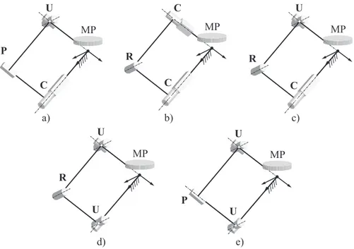
3 A class of tripod SPMs 27 3.1 Decomposition in minor-mobility PKMs . . . 27
3.2 A classification of SPMs . . . 30
3.3 An isostatic SPM class . . . 31
3.3.1 Redundancy Analysis . . . 32
3.3.2 Relevant joints screws . . . 32
3.3.3 Global Mobility Verification . . . 35
4 Kinetostatic Performance Index 43 4.1 General Velocity Analysis . . . 43
4.1.1 SPM Jacobian Matrices . . . 45
4.2 Condition Number . . . 47
4.2.1 Global Condition Number . . . 49
5 Dynamic Performance Indices 51
5.1 Manipulator Inertia Matrix . . . 51
5.2 Determination of the Z matrices . . . 53
5.3 Local Dynamic Indices . . . 55
5.3.1 Index of Dynamic Manipulability . . . 56
5.3.2 Condition number based on the Frobenius norm . . . 56
5.3.3 Manipulator swiftness . . . 57
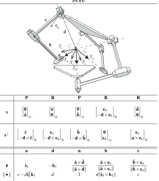
5.4 Example: 3-CPU . . . 57
6 Singularity analysis with ERPs 61 6.1 Singular configurations . . . 61
6.2 Rendering workspace with ERP . . . 62
6.3 Example: 3-CPU . . . 63
7 Posture Optimization 69 7.1 Formulation of the Optimization Problem . . . 69
7.2 Pointing Constraint Equations with ERP . . . 70
7.3 Unconstrained Optimization Problem . . . 75
7.4 Numerical solution . . . 77
7.4.1 A practical case: 3-CPU Sphe.I.Ro . . . 78
7.4.2 2-dof Vs. 3-dof Pointing PKM . . . 79
7.5 Extended Optimization . . . 80
8 Optimal Pointing Trajectory Planning 87 8.1 Bézier Curves lying on spheres . . . 87
8.1.1 Exponential Mapping . . . 88
8.1.2 Natural Invariants . . . 89
8.2 Optimization Problem . . . 91
8.3 Problem solution . . . 92
8.3.1 Quadratic Bézier curve: two-points boundary value problem . 92 8.3.2 Cubic Bézier curve: two-points and one-velocity boundary value problem . . . 93
8.3.3 4th-degree Bézier curve: two-points, velocity and one-acceleration boundary value problem . . . 96
List of Figures
1.1 six-axis PKM machining centers. a) Variax (Giddings & Lewis), b) Octahedral Hexapod HOH-600 and c) VOH-1000 (Ingersoll), d) Tor-nado (Hexel), e) HexaM (Toyoda). Video by clicking on the figure: G&L Variax advertisement. . . 9 1.2 Other six-axis PKM machining centers. a) HEXAPODE CMW 300
(CMW), b) SEYANKA (Tekniker), c) Eclipse-RP (Daeyoung Machin-ery), d) Cosmo Center PM-600 (Okuma). Video by clicking on the figure: Okuma PM-600 six-axis milling machine. . . 10 1.3 AMRC’s innovative robotic machining with FANUC F200iB PKM.
The video by clicking the figure shows the flexibility and accuracy of movement of the robotic system. . . 11 1.4 a) P2000 OKM designed by Mikrolar for milling application and b)
Fanuc 200iB with a milling spindle. . . 13 1.5 Picture and video of COMAU Tricept HP1 robot used for FSW at
UnivPM a) and b) Shi’s prototype of the PKM tool head for friction stir welding. . . 14 1.6 Hex-A-Jet (Mikrolar) for water-jet cutting: a) machining center and b)
detail of the hexapod PKM. Video by clicking the figure of a water-cut task. . . 15 2.1 Picture of Canadarm2 on the left and the scheme of its architecture
on the right. Video by clicking the picture shows the mobility of the Canadarm2. . . 23 2.2 A Stewart-Gough commercial platform: PI H-811.S11 six-axis
mo-tion hexapod a) and its advertisement on the video by clicking the fig-ure. The architecture scheme of a classical Stewart-Gough platform is illustrated in b). . . 25 3.1 The minor-mobility PKM prototypes developed at the Machine
Me-chanics Laboratory: the upper is I.Ca.Ro while the lower, Sphe.I.Ro. . 28 3.2 Virtual system architecture of a machining cell based on two
cooper-ating three-dof parallel robots conceptualized at UnivPM. . . 29 3.3 Virtual model (a) and prototype (b) of the spherical 3-CPU
3.4 Limb architectures of the three legged isostatic SPMs class: a) CPU, b) CRC, c) CRU, d) URU and e) UPU SPMs. . . 31 3.5 3-UPU SPM in a general configuration. Video by clicking the figure:
mobility verification through a spiral pointing trajectory of the MP. . . 34 3.6 Kinematics of the i-th leg for the class architectures. . . 36 6.1 Renderings of the singularity ellipsoid surfaces with the ERPs 3D
rep-resentation of the 3-CPU SPM: a) π1= 0, b)π2= 0, c) π3= 0 and d)
π4= 0. Lines indicate the intersection with the unit sphere. . . 65
6.2 Renderings with ERPs representation of the singularity ellipsoid sur-faces of the 3-CPU SPM: a) isometric view and b) upper view. Lines indicate the intersections with the unit sphere. . . 66 6.3 The four singularities surfaces for the 3-CPU SPM; Renderings with
ERPs representation of the pointing direction of the moving platform. 67 6.4 Renderings with a pointing ERPs representation of the moving
plat-form singularity surfaces of the 3-CPU SPM: a) isometric view and upper view b). . . 68 7.1 Sphe.I.Ro under trajectory-following: (a) at the initial posture; and
(b) evolution of 1/κf(opt) along the trajectory, with the time-histories
(qi) of the joint-coordinates, for i = 1, 2, 3. . . 77
7.2 Reciprocal of the condition number and joint values (a) time-histories for the middle (50th); and (b) final (100th) trajectory point. . . 79 7.3 3-CPU with a locked actuator to avoid functional redundancy under
spiral trajectory-following. The video shows first the task of the 2-dof 3-CPU and then the trajectory of the functionally optimal 3-dof machine. 80 7.4 Reciprocal value of the condition number a) and joint values
time-histories b) under spiral trajectory-following. Bold lines indicate the optimal 3-dof PKM while fine lines are the result for the 2-dof 3-CPU. 80 7.5 3-CPU optimization map of the condition number values: upper view
a) and isometric view b); directions of minimum and maximum values are indicated. . . 81 7.6 3-UPU optimization map of the condition number values: direct
Ja-cobian matrix Jd optimization a) Vs. single Jacobian matrix J−1i Jd
optimal values b). . . 83 7.7 3-UPU a) Vs. 3-CPU b) optimization maps of the Jacobian condition
number. . . 83 7.8 Reciprocal value of the Condition Number 1/κF based on the
Frobe-nius norm for some views of the sphere: a) is an upper view while b) an isometric view. . . 85
List of Figures 7.9 Reciprocal value of the dynamics indices of the inertia matrix;
dy-namic isotropy index a) and condition number based on the Frobenius norm b). . . 85 7.10 Reciprocal value of the dynamics indices of the inertia matrix.
Dy-namic isotropy index d1a) and swiftness b). . . 86
8.1 Steps of the De Casteljau’s algorithm to determine the point of the Bézier curve corresponding to t = 0, 7. . . 88 8.2 Cubic Bézier curve on RP2. e
1= [0, 0, 1]T, e2= [−1, 0, 0]T, e3=
[0, −1, 0]T, e4= −1/
√
3[1, 1, 1]T. . . 90 8.3 Optimal quadratic Bézier curve: 3-CPU a) Vs. 3-UPU b) dexterity
index. . . 93 8.4 Inverse dynamics simulations of the geodesic and the optimal
trajecto-ries. Symmetric-triangular velocity profiles on the top and the actuator force time histories on the bottom. . . 94 8.5 Optimal quadratic Bézier curve: 3-CPU dexterity index a) and
dy-namic condition number b). . . 95 8.6 Optimal cubic Bézier curve: 3-CPU a) Vs. 3-UPU b) dexterity index. 95 8.7 Optimal cubic Bézier curve: 3-CPU dexterity index a) and dynamic
condition number b). . . 96 8.8 Optimal 4th-degree Bézier curve: 3-CPU a) Vs. 3-UPU b) dexterity
index. . . 97 8.9 Optimal 4th-degree Bézier curve: 3-CPU dexterity index a) and
List of Tables
3.1 3-UPU joint screws of the first limb: the screw s of each joint and the screw s⊥reciprocal to all the joint in the chain except for the consid-ered joint. . . 34 3.2 3-UPU IKP: unit vectors and magnitudes of the relevant vectors in the
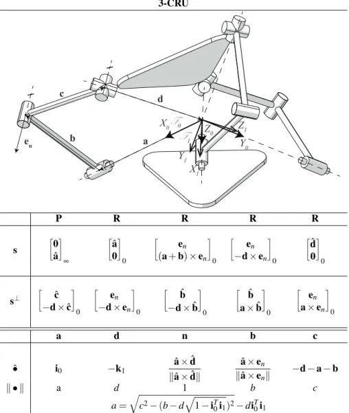
first leg. . . 35 3.3 3-CPU SPM screw joints, reciprocal screw joints and IKP of the first
limb. . . 39 3.4 3-CRU SPM screw joints, reciprocal screw joints and IKP of the first
limb. . . 40 3.5 3-URU SPM screw joints, reciprocal screw joints and IKP of the first
limb. . . 41 3.6 3-CRC SPM screw joints, reciprocal screw joints and IKP of the first
limb. . . 42 5.1 3-CPU: Inertia matrix, rotation matrix, center of mass position vector
and mass of the members 1,2 and 3 composing each leg j. . . 58 5.2 3-CPU: Inertia matrix, rotation matrix, center of mass position vector
and mass of the members 4 and 5 composing each leg j. . . 59 7.1 Comparison between the 3-CPU and 3-UPU GCI, both before and
0.1 List of Notation and Acronyms
0.1 List of Notation and Acronyms
In this dissertation vectors will be indicated with lower cases, while matrices with upper cases; both vectors and matrices have a bold font. e corresponds to a unit vector and the hat over a vector ˆa indicates its versor. The foregoing acronyms are often used:
KC: kinematic chain
PKM: parallel kinematics machine SPM: spherical parallel manipulator BP: base platform
MP: mobile platform EE: end-effector dof: degrees of freedom
Chapter 1
Introduction
This work is focused on the functional kinematic redundancy of parallel kinematics machines in the execution of industrial tasks. After a brief overview of the research project, this chapter addresses two subjects: the first is about parallel manipulators currently used in industrial processes and the second is about common manufacturing tasks that do not require a full mobility of the robot moving platform.
1.1 Overview of the Research Project
The evolution of production systems generates changing demands that are increas-ingly satisfied by the industrial robotics. Looking with a future perspective the major challenges that begin to take shape, they are aimed towards the improvement of per-formance of robotic devices which, depending on the need, may be facing either the increase of productivity by the reduction of time and energy consumption, or the ac-curacy improvement for the assigned task. To achieve these goals, some key enablers have been defined within the robotics research in favor of innovative design princi-ples of manipulators and combined with advanced control concepts. In conjunction with these, the guidelines of the new cells for mechanical machining require versatile manipulators that are used in the most recent flexible manufacturing systems (FMS) which are capable to automatically change the product productions. To meet the re-quirements of flexibility and versatility in the manufacturing processes, the choice of the robot employed often falls in manipulators of the more generic type, i.e. robots capable to position their moving platform with six degrees of freedom (dof).
Most of the tasks of high industrial relevance such as milling, welding, additive man-ufacturing and plasma, water and laser cutting are characterized by five degrees of freedom because they require the use of an axially symmetric device whose orienta-tion with respect to the axis of symmetry is irrelevant to the task to be performed. Therefore, with respect to the full-mobility manipulator used, i.e. a manipulator with six-dof, there is a redundant degree of freedom. This redundancy takes more specifi-cally the name of functional redundancy. It constitutes a potentiality that is exploited for optimization purposes in the research project carried out.
manufactur-ing processes, they have been ignored in industrial applications over the years and only recent studies have devised algorithms for its exploitation, highlighting the advantages of such optimization. The most widespread robots employed in manufacturing are se-rial manipulators due to their superior versatility and large workspace. Sese-rial robots are currently used to perform tasks in the most recent manufacturing cells, mainly be-cause they possess greater versatility and affordability when compared with five-axis numerical control machines at the expense of a lower stiffness. In machining opera-tions the stiffness is often a key factor due to the stringent demands on the dimensional tolerances of the machined pieces therefore parallel kinematics machines (PKM) carry the potentiality to satisfy the stated needs, because they usually offer a greater rigidity than serial robots.
The reason behind the lower stiffness of serial robots is inherent in the supporting ar-chitecture of the end-effector, as their outboard links are supported by their proximal counterparts. The serial-robot stiffness is, thus, equivalent to a serial array of springs, whose compliance is additive: the larger the number of springs connected in series, the more compliant the array becomes. On the contrary, the moving plate or the mo-bile platform of a PKM is supported in parallel by all its limbs, thus its stiffness is additive: the more limbs the PKM carries, the larger its stiffness is.
The optimization problems associated to functional redundancy situations have been already solved for serial robots [1], while this work is focused on parallel manipula-tors. Parallel kinematics machines are not widespread at the industrial level due to their smaller workspace. However, compared to serial robots, they offer better dy-namic performance due to actuators fixed to the frame instead of the movable arms and, as already said, increased stiffness of the structure. Therefore, when they are used for mechanical machining, they allow the products to achieve more stringent ac-curacy specifications. Since the acac-curacy of such manipulators fits in well with the functional redundancy optimization, the algorithms developed so far for serial manip-ulators will be reviewed in this thesis for applications to parallel manipmanip-ulators. The functionally redundant motions, i.e. the movements that a robot can perform without affecting the assigned task, are often exploited for optimization purposes of parameters such as the dexterity or the swiftness of the manipulator. More in details, the robots are considered functionally redundant because the dimension of the oper-ational space (Cartesian space accessible by the moving platform) is larger than the dimension of the task space (Cartesian space of the task). The application of this con-cept for the optimization of parallel manipulators has not been exhaustively addressed in the literature yet, therefore it represents a fascinating topic of research.
One of the issues in the analysis of parallel manipulators with six-degrees of free-dom is the complexity of their kinematic model, which can adversely affect the path planning. What is sometimes done in conventional processes is to separate the full-mobility task in sub-elementary tasks performed by separate machines with lower mobility. The mobility decomposition allows even the control algorithms to be split
1.1 Overview of the Research Project and the most common division is made up of two three-dof machines where one has 3 degrees of freedom for the translation of its moving platform (EE) while the other executes motions of pure rotations (three-dof). Obviously, in this case, the functional redundancy is owned by the spherical robot which can perform rotational redundant motions around the symmetry axis of the tool. In this thesis a class of spherical par-allel robots (3-dof of spherical motion about a fixed point) is taken into account. All the considered SPMs are isostatic and have three identical legs: the machines of this class have different topology, i.e. different sequence of the joints in the leg. This study aims at the formalization of the optimization problem and at the partial generalization of the problem. In fact, the presented approach is applicable to every spherical robotic manipulator with a single degree of functional redundancy and no degree of intrin-sic redundancy. In other words, to parallel kinematics machines characterized by a single dof difference between the operational and the task spaces, while the joint and operational space dimensions are equal.
1.1.1 Initial objective
At Machine Mechanics Laboratory, a novel architecture for an assembly cell has been developed decomposing the full mobility of a single manipulator in two PKMs with lower mobility: a spherical PKM and a translational one. Although the manufacturing cell has been widely used to assemble various mechanical parts, other manufacturing operations are not excluded. Acknowledging that the majority of the industrial tasks require a low number of degrees of freedom, the problem of exploiting the degree of functional redundancy of the spherical manipulator has emerged. Although functional redundancy can be used to increase the accuracy of the manipulator above what is currently available, as reported by Léger and Angeles [2] for serial robots, a compre-hensive study has not been yet provided for parallel manipulators. Hence, the aim of the thesis is the optimization of tasks performed by functionally redundant parallel robots. This work, in the framework of maximizing robot performance, consists of devising optimum five-dof machining operations with the PKMs mentioned above. A motivation of this work is that the exploitation of functional redundancy to improve performance of PKMs may be a key factor for their wider use in manufacturing appli-cations and beyond.
1.1.2 Methodology and tools
This work has made extensive use of screw algebra to describe the behavior of robots. The mathematical framework of this theory was firstly developed by Sir Robert Stawell Ball [3] and then recovered by Hunt [4], who applied screw theory to study the kine-matics of spatial mechanisms, with special emphasis on the analysis of singularities. Although PKMs are known to posses a higher complexity of the kinematics and dy-namic relationships, the application of this tool brings advantages in terms of
analy-sis and syntheanaly-sis and a more compact representation of equations. The mathemati-cal relationships have been verified and implemented with computer algebra both for symbolic computation and the numerical solution of optimization problems. Virtual models of the mechanical systems have been build inside a CAD environment, while a CAE software has been used for mobility verification and for animation purposes. The project methodology is directed towards finding the optimum posture at an in-completely specified posture, i.e. out of the six scalar quantities (three Cartesian point coordinates and three independent orientation variables) defining a rigid-body pose, only five are specified in machining operations using a turning tool (the orientation of the tool about its axis of rotation is left unspecified). This unused dof is exploited to maximize robot performance.
1.1.3 Publications arising from the research
Part of the work on the posture optimization exploiting functional redundancy, which will be developed in Chapter 5, has been applied to a practical case study of a spherical PKM performing an assembly task. This project was presented at the Advances in Robot Kinematics(ARK) conference and it is available in a open source version. The reference of the printed version of the paper is
• D. Corinaldi, J. Angeles and M. Callegari, "Posture Optimization of a Function-ally Redundant Parallel Robot", in Springer Proceedings on Advanced Robotics (SPAR). Springer, 2017.
1.2 Industrial Parallel Robots
Among the wide range of programmable robotic mechanical systems, this thesis deals with the industrial types of robots called manipulators. A manipulator, in general, is a mechanical system aimed at object manipulation. They deserve special attention for various reasons: the arm is the simplest robotic form and hence, appears as building blocks of other, more complex robotic mechanical systems. Two types of industrial manipulators can be distinguished: serial and parallel. The serial manipulators have an open chain architecture like an human arm, while, from Merlet’s book [5] a paral-lel mechanism is defined as a multi-degree-of-freedom (multi-DOF) mechanism com-posed of one moving platform (MP) and one base platform (BP)connected by at least two serial KCs in parallel. These serial KCs are called legs (or limbs). Because of the closed-loop architecture, not all of the joints can be independently actuated and usu-ally the number of actuated joints is selected to be equal to the number of degrees of freedom of the manipulator. Parallel manipulators whose number of chains is strictly equal to the number of d.o.f. of the moving platform are called full-parallel kinemat-ics machines. Similarly, they are called full-mobility parallel manipulator when they can position and orient its mobile platform with six-dof. From a constructive point
1.2 Industrial Parallel Robots of view there are many choices regarding the type of legs, joints and numbers of at-tached legs to the platform which can be significant factors when the workspace and actuation requirements are determined. When the legs of the parallel manipulator are identical the robot is called symmetrical. The discussion will focus on symmetrical parallel manipulators.
1.2.1 Characteristics of PKMs
The first prototypes of parallel kinematics machines were enthusiastically welcomed in 1994 as the new generation of machine tools thanks to their specific characteristics that guarantee better performance [6], namely:
• simpler solution of the inverse kinematics problem IKP; • noncumulative joint error;
• higher structural rigidity: the load is carried by the parallel links, and in some structures there are only compression-tension modes;
• modularity: each kinematic chain is composed of the same physical modules. • Locating the actuated joint adjacent to the fixed base, rather than attaching it
midway in an articulated leg like the traditional Stewart-Gough platform 2.2, is considered advantageous [7].Such architectures proved to be beneficial based on the following factors [8]:
– absorption of major portion of reaction forces by the ground resulting in almost vibration-free operation with light-weight mobile components; – reduced effect of inertia due to the elimination of actuator’s weight; – absence of interference of actuators and routing cables due to base location
of actuators;
– further, by selecting the base actuated joint to be prismatic, the proximal links are not subjected to the bending moments and the corresponding stresses.
Contrary to serial robots, where all joints are actuated, parallel robots are supplied with unactuated joints, which brings about a substantial difference between the two types. The presence of unactuated joints makes the analysis of parallel manipulators, in general, more complex when compared to serial robots. However, PKMs suffer from
• singular configurations, a well-known problem in the robotics field; • a low workspace-to-footprint ratio;
• more difficult control techniques.
The kinematics and dynamics behavior of the physical machine is strongly influenced by manufacturing tolerances and assembly errors, and so, especially for machining applications, calibration strategies must be defined and consolidated. Functional op-timization may further increase the performance of these manipulators. To this aim, this research could be a stimulus to their spread in the manufacturing field. In fact, once PKM performance as a machine tool reaches high level, economy of scale will solve any cost issues due to their production.
1.2.2 PKM machining centers (1960-2000)
Despite a wide range of PKM architectures have been proposed, nowadays the most popular implementation on a commercial scale is the Stewart-Gough platform born from the early days of the parallel robotics [9].
Jaime Gallardo-Alvarado [10] reveals that the first attempts in parallel machine de-sign have been made for cinematography industry in 1931 by Gwinnet. He proposed a spherical parallel manipulator as a cinema motion simulator. Several years later, a more practical application of a parallel manipulator was introduced by Willard I.V. Pollard (1940): a spray painting machine consisting on a five-dof three-branched par-allel robot. Unfortunately, both those two parpar-allel robots were never built. A couple of years later, in 1947, the nowadays called Stewart-Gough platform was invented, i.e. the variable-length-strut octahedral hexapod. This parallel robot became the most popular, because it changed industry, and was replicated over a thousand times. Dr. Eric Gough was the person who built this machine in the early 1950s, as a universal tire-testing machine. However, it was Klaus Cappel who later designed independently the very similar hexapod. He patented it, licensed it to the first flight simulator com-panies, and made the first commercial octahedral hexapod motion simulators. Yet, it was Stewart in 1965 who, unintentionally, made Gough’s concept popular and pro-posed the idea for flight simulators, this time to academia.
In 1966 Tindales [11] proposed the use of parallel kinematics machining for manufac-turing processes; however, a great interest grown for the application of these mech-anisms in the metalworking field only in the 90s [6]. The first CNC-type hexapod machine tool prototypes (Variax from Giddings & Lewis Fig. 1.1 a) and the Octahe-dral Hexapod from Ingersoll Fig. 1.1b and c) were presented at the 1994 International Machine Tool Show (IMTS) in Chicago. These prototypes were enthusiastically wel-comed as the new generation of machine tools due to their specific characteristics that should guarantee better performance, as described in the previous subsection. All of these advantages induced machine tool builders and researchers to investigate the applications of parallel kinematics machines for six-axis machining, a field where traditional machine tools had not gained the hoped-for success yet. Since the 1994 debut, several other prototypes of parallel kinematics machines have been built and
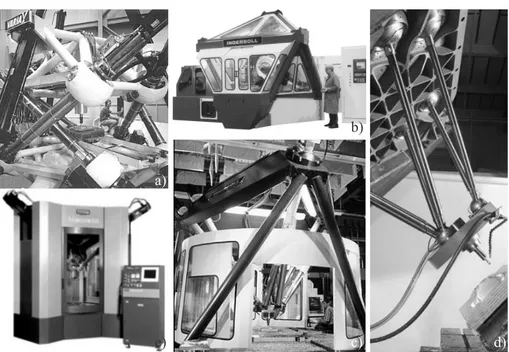
1.2 Industrial Parallel Robots a) b) e) c) d) c)
Figure 1.1: six-axis PKM machining centers. a) Variax (Giddings & Lewis), b) Oc-tahedral Hexapod HOH-600 and c) VOH-1000 (Ingersoll), d) Tornado (Hexel), e) HexaM (Toyoda). Video by clicking on the figure: G&L Variax advertisement.
commercialized: Fig.s 1.1 and 1.2 show an a non-exhaustive list of six-axis PKM ma-chining centers between the years 1960 and 2000. A chronological list of European key patents was presented by Pritschow [12] during the 1stEuropean-American Forum on Parallel Kinematics Machinesheld in Milan in 1998. Other prototypes of PKMs for machining operations were presented during the EM0 in Paris, and it was claimed that this exhibition might mark the rebirth of PKMs. According to Tonhoff, more than 90% of existing PKM prototypes in the 2000s and employed in the machine tool sec-tor where high stiffness is required, are fully parallel. Moreover, most of them belong to the Stewart-Gough type even though the technology of joint manufacturing allows rotations of the mobile platform to be limited to 30 degrees. Nevertheless, as high-lighted at the 1999 EM0 in Paris, many new prototypes with different architectures from the Stewart platform are appearing.
1.2.3 Advances on PKM
Today, the research stream on PKM is still active and requested, as evidenced for example in Europe by the Robotic Roadmap for financial support of the H2020 pro-gram. According to these guidelines, the goals for mechanical systems design can be summed up as smaller, lighter, faster, stronger. In this framework, a relevant
technol-a) b)
c) d)
Figure 1.2: Other six-axis PKM machining centers. a) HEXAPODE CMW 300 (CMW), b) SEYANKA (Tekniker), c) Eclipse-RP (Daeyoung Machin-ery), d) Cosmo Center PM-600 (Okuma). Video by clicking on the figure: Okuma PM-600 six-axis milling machine.
ogy target is redundancy optimization: new control paradigms with constraint-based optimisation and the use of task redundancy for best trade-off among different objec-tives (e.g. productivity, manipulability, safety, ergonomics, etc.). By way of example, a very active research center for Research and Innovation in the field of PKM manu-facturing is the Nuclear Advanced Manumanu-facturing Research Centre (Nuclear AMRC) at the University of Sheffield. The ARMC receives significant investments by the Eu-ropean Commission to innovate manufacturing processes in particular in civil nuclear field. A Research involving the Nuclear AMRC’s innovative robotic machining cell with a PKM has been presented at a high-profile engineering conference in Toulouse, France (2011). The project aims to develop a single automated system which can carry out a range of processes such as machining, welding, dressing and inspection over a large area to very high precisions. The robot cell is based around a hexapod PKM from Fanuc Robotics which can carry a variety of tool heads, e.g. in Fig. 1.3 the PKM carries a milling spindle. The FANUC F200iB parallel robot which has been implemented is engineered for applications requiring extreme rigidity and exceptional repeatability. The robot’s position is tracked by an indoor GPS system and in trials, accuracies of 0.2 mm have been achieved. However, further improvements could be done with the solution of the optimization problem to find the best posture due to
1.3 Industrial relevance of five-dof tasks
Figure 1.3: AMRC’s innovative robotic machining with FANUC F200iB PKM. The video by clicking the figure shows the flexibility and accuracy of move-ment of the robotic system.
functional redundancy, as evidenced by recent research developments. In fact, their research is still active in the field of advanced machining and surfacing for the New Nuclear Manufacturing (NNUMAN) project [13, 14]. NNUMAN researchers report that future designs for large nuclear vessels and components will require more efficient machining techniques for both existing and future reactor materials. The research center is leading research to develop and characterize optimised cutting techniques, which include key aspects of machine dynamics. This research explores highly inno-vative approaches for machining very large components, for example using deep-hole drilling and using machining robots with indoor positioning systems, together with assisted machining techniques.
1.3 Industrial relevance of five-dof tasks
Parallel robots have left academic laboratories and have found their way in an increas-ingly larger number of application fields, such as telescopes, fine positioning devices, fast packaging, medical and machine tool. A wide range of industrial applications do not require to fully position the robot EE in the Cartesian space, i.e usually the dimen-sions of the task space have a dimension lower than six, i.e. lower than the complete dimension of Cartesian space. This is because the moving platform holds a tool for the manufacturing task, e.g. a spindle for milling, that has an axial-symmetry. The rotation of the MP along this axis is irrelevant for the task. Only five dof are speci-fied in machining operations using a turning tool: the orientation of the tool about its
axis of rotation is left unspecified and optimization strategies should be used to find the best robot posture to maximize robot performance. In this section, a research was tackled on industrial processes that requires five dof: milling, tape laying, additive manufacturing and plasma, water jet and laser cutting are five-dof task common in manufacturing operations. A non-exhaustive list of these task is proposed, offering to the reader reflections on possible advantages provided by redundancy exploitation.
1.3.1 Machining with PKMs
Compared to a milling machine or a lathe, serial robots possess much less stiffness (by a factor of 20–50 times), but much greater dexterity. A widely accepted definition states that the dexterity of a robotic moving platform is a measure of its capability to change the manipulated object configuration from an initial configuration to a fi-nal one, arbitrarily chosen within the device workspace. A serial robot’s stiffness is usually very anisotropic throughout its workspace and may vary for a typical heavy duty model in the range 200 − 700N/mm. Therefore, robots can machine workpieces (grinding, fettling, polishing etc.) provided that tool forces can be reduced to accept-able values for a given robot manipulator. This incremental approach to machining, particularly for cutting and forming, can produce good results. The choice of mecha-nism, its kinematic properties, the computation methods used to determine joint mo-tions, and the intended application of a robot manipulator are all closely related. With advances in the state of the art in kinematic algorithms and computer hardware pro-cessing capabilities, computation is much less of a constraint on mechanism choice than it was for early robot designers. For this reasons, the use of PKM can be a great compromise ensuring high forces but generally reducing the work space. The choice of mechanical structure of the PKM depends mostly on fundamental mechanical re-quirements such as payload and workspace size. Considering a given level of cost, there is usually a tradeoff between workspace size and stiffness.
Milling
The milling machine is one of the most important tool used in today’s manufactur-ing industry, mostly used to cut special mechanical parts. The diffusion of parallel robots, instead of conventional gantry CNC machines for machining operation, arises from the need to obviate the low rigidity of the cantilever-link structure and the posi-tioning errors of the cutting tool due to the actuator error accumulations. Despite the low workspace and dexterity, a PKM possesses high stiffness, high accuracy, higher load-carrying and lower inertia. To this aim six-dof hexapod PKMs are generally used, because they support the tool from six different directions. The stiffness of the structure is well conciliated with the choice of leaving the motors to the base to have a relatively light structure and thereby low inertia, features that improve the perfor-mance for the high-speed machining.
1.3 Industrial relevance of five-dof tasks
a) b)
Figure 1.4: a) P2000 OKM designed by Mikrolar for milling application and b) Fanuc 200iB with a milling spindle.
Functional redundancy optimization could outperform the machine competition, feed-ing the demand on high quantities of dimensionally accurate and inexpensive parts that has increased as a result of technological progress. The optimal motion could offer better cutting efficiency and improve surface finish as well as machinability, pursuing the current research trend driven by the increasing requirements for cost competitions, process chain reduction and for developing economical and efficient manufacturing processes.
Welding: Friction Stir Welding (FSW)
Friction Stir Welding (FSW) represents one of the latest innovative techniques in the area of welding for its advantages over conventional fusion joining technology. As a matter of fact, typical drawbacks associated with conventional fusion welding, such as shrinkage, porosity and distortions, are eliminated to a great extent by FSW since it is a solid state process. Therefore, materials considered difficult to be fusion welded, such as aluminium and magnesium alloys, can be successfully friction stir welded [15, 16]. Friction stir welding can be applied in many industrial field, such as automotive, ship-building, aerospace and railway industries [17].
However, in some of these applications, FSW could be scarcely competitive since the high welding forces require expensive customised machines that, in turn, also cause relatively high productivity losses due to the inability to achieve high duty cycles. The large axial force to be maintained between the welding tool and workpiece is the pri-mary requirement of FSW process, which has also been a great obstacle to the design and application of FSW in manufacturing. Further complicating the issue is the need
to perform FSW over three-dimensional contours, which requires a mechanism dex-terous enough to set the stir pin used in welding to track a predefined trajectory with prescribed poses. Unlike common computer numerical control machining centers, often provided with only three motion axes, industrial robots have a high degree of mobility, which gives them an intrinsic versatility in accomplishing welding of com-plex geometries, also with tight radii of curvature.
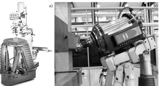
Such drawback can be overcome by developing robotic FSW [18]. However a force feedback control, which is mandatory for compensating the reduced machine struc-tural stiffness, often it is not sufficient for a serial robotic arm to ensure a high axial force. Therefore, in order to overcome the low-stiffness issues of serial robots, re-searchers at Polytechnic University of Marche proposes to employ a six-axis robot with a hybrid structure [19], characterised by an arm with parallel kinematics and a roll-pitch-roll wrist with serial kinematics, as illustrated in Fig. 1.5a). Shi et al. [20]
a) b)
Figure 1.5: Picture and video of COMAU Tricept HP1 robot used for FSW at UnivPM a) and b) Shi’s prototype of the PKM tool head for friction stir welding. proposed the application of a 3-PRS parallel mechanism (tripod PKM with a pris-matic, a revolute and a spherical joint in each limb) as a welding tool head and em-ployed it to form a five-axis welding machine tool for FSW. The optimal design of the PKM was carried out by the authors, and the kinematic dexterity is estimated over the whole orientation workspace for optimization purposes. In the author’s opinion, the full potentiality of parallel robotic for FSW has not been sufficiently investigated notwithstanding this system provides a very high flexibility and requires relatively low investments. Even for this application the functional redundancy that emerges from the use of a six-axis parallel robot, could further increase performance parameters. Water jet cutting
Water jets are applied in nearly all areas of modern industry, such as automotive indus-try, aerospace indusindus-try, construction engineering, environmental technology, chemical process engineering, and industrial maintenance [21]. In the past, water jet
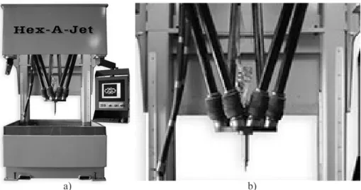
applica-1.3 Industrial relevance of five-dof tasks tions have mostly been three-axis tasks: this fact has limited the number of parts that can be cut with a water jet, even if sometimes this technology would be better, faster and cheaper. Multi-axis surfaces, tapered edges or accurate non-tapered edges, cast-ing flash removal and many other parts can be completed with the use of a six-axis PKM as a waterjet machine. An interesting commercial application of PKM for water jet cutting comes from Mikrolar company, that designed and produced high precision positioning systems. Mikrolar has also addressed significant issues in the manufactur-ing area and as a result has developed and patented a six-dof PKM system for rapid measuring, programming and water jet cutting of complicated or irregular parts called Hexa-A-Jetand showed in Fig. 1.6. The device is purpose-built to allow an operator
a) b)
Figure 1.6: Hex-A-Jet (Mikrolar) for water-jet cutting: a) machining center and b) detail of the hexapod PKM. Video by clicking the figure of a water-cut task.
to measure each individual part and then transfer that part directly to the water jet system for rapid material removal. The inherent design of the hexapod contributes to a high mechanical stiffness while the exploiting of functional redundancy could allow the workpiece to achieve the most stringent dimensional specifications.
Chapter 2
Kinematic Redundancy
The core concept of this dissertation is the functional redundancy, which represents a particular class of kinematic redundancy of a robot with respect to a particular task. In the past, such kind of redundancy found several appellations so that literature can lead to ambiguous definitions or even misunderstandings. In this chapter, the definitions of redundancy are reported as they were established for serial robots, and are extended to parallel manipulators. In the remainder of the section, the redundancy analysis of a class of parallel manipulators is performed by means of screw theory with the aim of quantifying their degree of kinematic redundancy.
2.1 Definitions
The kinematic redundancy is not an intrinsic feature of a machine, but rather a con-cept related to both manipulator and the task to be performed. In other words, if a manipulator is redundant for a specific task, it may not be redundant for another one. To properly define the redundancies, three spaces have to be identified:
• the joint-spaceJ is the space of the independent actively controlled joint vari-ables or actuated joint varivari-ables;
• the operational-spaceO is the Cartesian space reachable by the moving plat-form, whether a serial robot or a parallel robot is considered;
• the task-spaceT is the Cartesian space of the task.
Obviously, each space, that more precisely is a submanifold of SE(3), is characterized by a dimension. For the robot to be able to accomplish a task, the relations below should always be satisfied, even if redundancy is not available.
• dim (T ) ≤ 6, task space dimension cannot exceed the maximum number of de-grees of freedom of a rigid body in the space (3 translational dof and 3 rotational dof);
• T ⊆ O, the task-space is totally included into the operational space of the manipulator, otherwise the task cannot be performed by the robot. Hence, dim (O) ≥ dim(T ).
• dim (T ) ≤ dim(O) ≤ dim(J ), the dimension of the operational-space is be-tween the two other space dimensions. dim (J ) has the greatest value and represents the global mobility of the robot.
At first sight, a simple comparison of the number of actuated joint variables and the number of degrees of freedom by the task indicates whether a given kinematic struc-ture can be considered redundant or not.
Definition 2.1.1. A pair made of a manipulator and a task is said to be kinematically redundant when the dimension of the joint-spaceJ , is greater than the dimension of the task-spaceT .
dim (J ) > dim(T ) ⇔ kinematicredundancyofrobot − task (2.1) In other words, a kinematic redundant mechanism is a mechanism with more ac-tuators than the number of controlled degrees of freedom required by the task. The degree of kinematic redundancy of a pair manipulator-task, namely rk, is computed as
rk= dim (J ) − dim(T ) (2.2)
However, definition 2.1.1 does not take into account the operational space. A more rigorous definition distinguishes among functional and intrinsic redundancy.
Definition 2.1.2. A manipulator is said to be intrinsically redundant when the dimen-sion of the joint-space is greater that the dimendimen-sion of the resulting operational space. dim (J ) > dim(O) ⇔ intrinsicallyredundancyrobot (2.3) Definition 2.1.3. A pair made of a manipulator and a task is said to be functionally redundant when the operational-space dimension is greater than the dimension of the task-space.
dim (O) > dim(T ) ⇔ functionalredundancyofrobot − task (2.4)
From these two definitions 2.1.2 and 2.1.3, the degree of intrinsic and functional redundancy for a manipulator and a task, named respectively rIand rF are computed
as
ri= dim (J ) − dim(O) (2.5)
rf= dim (O) − dim(T ) (2.6)
Clearly, from Eq.s (2.5) and (2.6) the total degree of kinematic redundancy of Eq. (2.2) can be rewritten as
2.2 Redundancy Analysis which makes clear that kinematic redundancy comes from two different sources: the functional and the intrinsic redundancy.
2.2 Redundancy Analysis
Redundancy analysis of robots and tasks aims to determine their degree of kinematic redundancy. Since the dimensions of the various spaces are required, the analysis is usually based on the mobility criterion of a mechanism which can take different forms. The general or full-cycle mobility of the manipulator of degree m = dim (J ), i.e. the number of independent variables needed to specify any configuration of the manipulator, may be determined from the well known Chebychev-Grübler-Kutzbach’ formula: m= 6 (l − n − 1) + n X i=1 di (2.8)
where l is the total number of members (including the base), n the total number of joints and di the number of degrees of freedom of the joints of the ith chain. It is
well known that the classical Chebychev-Grübler-Kutzbach mobility criterion 2.8, which is based solely on topology, fails to provide the correct mobility in many in-stances. In order to clarify such issue, the analysis of the kinematic chains mobility is carried out by employing the concept of screw, which allows linear/angular veloci-ties or torques/forces to be represented in six-dimensional vectors, namely twists and wrenches. In kinetostatics, a body’s instantaneous motion is represented by a twist, while a system of forces acting on the body is given by a wrench. Screws are classes of twists (or wrenches) that are scalar multiples of each other. In classical geometrical terms, the finite-pitch screw of a twist is given by a line, i.e. the screw axis, and a metric quantity, i.e. the pitch. Infinite-pitch screws are pure directions (free vectors corresponding to instantaneous translations or force couples), obtained as a limit case when either the screw axis or the pitch goes to infinity [22]. The mobility analysis developed by Kong and Gosselin [23] is taken up and adapted for the determination of the kinematic redundancy. The approach, based on screw theory, allows the instan-taneous mobility of the machine to be detected, however, it can be extended to the full-cycle mobility.
The instantaneous motion of the moving platform, whether it is held by a single or multiple kinematic chains, is represented by its twist system. A system that requires a minimum of t linearly independent screws for its description is called a t-system. The constraints on the EE provided by the links of a serial KCs, by means of the KC joints, can be expressed as the screw system reciprocal to the twist system, which is usually called the wrench system of the KC. The wrench system of a KC is a w-system, and for the reciprocity bond w = 6 − t. Twist and wrench systems, whose order is re-spectively t and w, are screw systems obtained by associating a scalar, i.e. the twist
amplitude (or the wrench intensity), to a screw. A screw system of order n (0 ≤ n ≤ 6) comprises all the screws that are linearly dependent on n given linearly independent screws. According to the definitions of the spaces of the previous subsection, if the twist system does not change order when the moving platform undergoes a small dis-placement from a general configuration, the order of twist system of the EE t is equal to the dimension of the operational space, i.e. t = dim (O). The mobility m or global mobility of a manipulator is the sum of
• the number of independent parameters required to determine the relative con-figuration of the moving platform and
• the number of independent parameters required to determine the configuration of all the links in all the legs with the relative configuration of the moving plat-form specified.
For an m-dof mechanism, m is equal to the dimension of the joint space, m = dim (J ) and it is also the number of the actuated joints whenever the robot is not intrinsically redundant.
2.2.1 Serial Kinematic Chains
In a serial manipulator the moving platform is connected to the ground by a single kinematic chain. The algorithm for the determination of the degree of functional re-dundancy is divided into the following steps:
Step 1. The mobility m of a serial KC is equal to the sum of the degrees of freedom of all its joints. Revolute joints (R), prismatic joints (P) are one-dof joints, universal joints (U) and cylindrical joints (C) leave two-dof, while, the spherical joints (S) three-dof. Joints with more than one-dof can be substituted in the kinematic chain with a series of one-dof joints that are kinematically equivalent.
Step 2. The twist systemT or the wrench system W of the KC must be de-termined. In a serial manipulator these systems coincide for the MP and for the KC. The output twist of the moving platformT is the summation of the twists of the j jointsTcof the KC.
T =
m
X
j=1
Tc (2.9)
Due to the reciprocal bond between twists and wrenches, it is possible to assert that the wrench system of the KC W coincides with the intersection of the
2.2 Redundancy Analysis wrench spacesWcthat are reciprocal to each joint twist:
W =
m
\
j=1
Wc (2.10)
Identifying a wrench space reciprocal to a given twist system is a simple linear operation. A non-exhaustive list of rules aimed at identifying wrench systems composed by zero-pitch and infinite-pitch screws was proposed by Kong and Gosselin. As already said, every joint with more than one dof in the kinematic chain is kinematically equivalent to a series of revolute (R) and prismatic joints (P) allowing the KC to be decompose as a series of R and P joints. In a KC with R and P joints, the following rules can be followed based on the reciprocity condition of screws:
– There is a 0-pitch wrench in the wrench system, which represents a force constraint exerted by the chain on the terminal, if its direction is coplanar to the axes of any R joint in the KC and it is perpendicular to the direction of any P joint in the KC.
– There is ∞-pitch wrench in the wrench system, which represents a torque exerted by the KC on the terminal, if its axis is perpendicular to the axis of any R joints in the KC.
The mobility obtained using twists and wrenches is an instantaneous character-istic of the chain. When t and w are the same in different general configurations, the mobility m is said to be full-cycle.
Step 3. With this assumption, the degree of intrinsic redundancy riof the serial
chain, is the difference between the dof of the serial chain m and the order of the twist system of the KC t. By using Eq. (2.9) to determine the twist system of the EE, the Eq. (2.5) with a different notation becomes:
ri= m − t (2.11)
Given n t-system, there is a unique reciprocal screw system of order (6 − n) which comprises all the screws reciprocal to the original screw system. There-fore, we have
t= 6 − w (2.12)
Eq. (2.11) can be rewritten in term of the wrench system order w instead of t
rf= m − 6 + w (2.13)
which is more useful if the wrench system is obtained using the rules defined. Step 4. The number of the dof requires by the task allows the degree of
func-tional redundancy rf to be calculated through the formula Eq. (2.20):
rf = t − dim (K ) (2.14)
Step 5. Finally the degree of kinematic redundancy rkcould be calculated with
Eq. (2.7).
Following this line of reasoning, to create an intrinsically redundant dof there will be a linear dependence between the joint twists in the KC. The conditions for the twists of the joints within the same leg to be linearly dependent are not difficult to address if the KC is composed of only R and P joints. For brevity, such conditions are listed below without explanation [23]:
1. there are no coaxial R joints;
2. there are no P joints along the same direction;
3. the direction of at most one P joint is parallel to the axis of an R joints; 4. at most three R joints have parallel axes;
5. the axes of at most three R joints pass through the same point; 6. the directions of at most two P joints are parallel to the same plane;
7. the sum of the number of R joints with parallel axes and the number of P joints is not greater than four;
8. if the directions of nP P joints are perpendicular to the axes of nR R joints with parallel axes, then nP + nR ≤ 3;
9. There are at most six R joints in the KC. Example: 7R Canadarm2
The Canadarm2 used on the International Space Station is a 7R serial manipulator. The algorithm to determine its degree of kinematic redundancy is applied:
Step 1. The total number of dof of the joints is m = 7, because there are seven R joints in the KC with one-dof.
Step 2. The wrench system of the EE is a 0-system (w = 0) because no screw can be found that respect the rules 2.2.1, i.e. it is coplanar with any R joint axes or perpendicular to any of them. Therefore, t = 6 − w = 6, i.e. the twist system attains its maximum order and the EE can be relatively positioned with six-dof. Step 3. The degree of intrinsic redundancy is equal to one ri= m − t = 1, in
2.2 Redundancy Analysis R R R R R R R
Figure 2.1: Picture of Canadarm2 on the left and the scheme of its architecture on the right. Video by clicking the picture shows the mobility of the Canadarm2.
Step 4. If the task is to position and orient the astronaut in the entrance to the space station, it is a six-dof task, therefore the degree of functional redundancy is rf = 0.
Step 5. The total degree of kinematic redundancy is rk= 1.
2.2.2 Parallel Kinematics Machines
A parallel manipulator is constituted by more than one serial kinematic chains which connect the base platform (BP) to the moving platform (MP). The redundancy anal-ysis resumes the analanal-ysis for the serial chain because steps 1-3 are first performed to each kinematic chains of the parallel kinematics machine PKM, disconnected from the platforms. Their contribution is then extended to the mobile platform. The method is here proposed:
Step 1. First of all, each leg of the parallel mechanism should be considered and treated as a serial kinematic chain. Due to this, steps from 1 to 3 of the previous method have to be performed for each kinematic chain indicated with the sub-script c. As a consequence, ricdegrees will be found of intrinsic redundancy,
with c = 1, ..., p.
Step 2. The number of independent parameters needed to determine the config-uration of all the links in all legs with the relative configconfig-uration of the moving platform specified is the intrinsic redundancy degrees of the PKM and it is the
sum of the intrinsic redundant dof of all the legs: ri= p X c=1 ric (2.15)
where riis the degree of intrinsic redundancy of the PKM.
Step 3. Once the twist-system of each leg of order tcis found, the mobility of the
MP, i.e. the number of independent parameters to determine the configuration of the moving platform is equal to order t of the twist system of the PKM. Therefore, t is equal to the order of the operational space of the PKM and it is also called the connectivity of the moving platform. The twist systemK of the MP is the intersection of the twist systemsKiof all its legs
K =
p
\
c=1
Kc (2.16)
Contrary to what happens for the serial chains, the output wrench-systemW of order w of the moving platform is the linear combination of the wrench systems Wiof all its legs:
W =
p
X
c=1
Wc (2.17)
Even in this case, Eq. (2.12) is valid . The instantaneous analysis is extended to the full-cycle mobility if the order of the system screws involved are the same for others general configurations of the PKM.
In addition to the order of the twist system of the MP, another important index of a PKM is defined as ∆ = p X c=1 wc− w (2.18)
where ∆ is called the number of over-constraints (also passive constraints) if ∆ > 0.
Step 4. The mobility m of the PKM, i.e. the number of independent parameters to determine the configuration of the manipulator is the sum of the mobility of the MP t and the degree of intrinsic redundancy ri.
m= t + ri= 6 − w + p
X
c=1
ric (2.19)
mis also the number of the actuated joints or active joints of the parallel robot and it is equal to the dimension of the joint space. Clearly, unlike a serial robot, in a parallel robot there are usually passive joints.
2.2 Redundancy Analysis Step 5. The number of dof required by the task allows the degree of functional redundancy rf to be calculated through the formula:
rf = t − dim (K ) (2.20)
Step 6. Finally the degree of kinematic redundacy rkcould be calculated with
Eq. (2.7).
This redundancy analysis will be illustrated using an example of a PKM performing a task.
Example: 6-UPS PKM Stewart-Gough platform
U
R
S
MP
BP
Figure 2.2: A Stewart-Gough commercial platform: PI H-811.S11 six-axis motion hexapod a) and its advertisement on the video by clicking the figure. The architecture scheme of a classical Stewart-Gough platform is illustrated in b).
Consider a Stewart-Gough platform, a six-legged PKM, shown in Fig. 2.2a. From the architecture scheme Fig. 2.2b, the direction of the P joint of each leg intersects the center of both the universal and the spherical joints, located at the BP and at the MP respectively. The parallel robot has six identical legs and so it is called symmetrical parallel manipulatorwith URS topology.
Step 1. For each KC mc= 6 (two dof for the universal joint, one dof for the
prismatic joint and three dof for the spherical joint), while the order of the twist system is tc= 6, no one screw can be found that respects the previous conditions.
Thus, ric= 6 − 6 = 0 for c = 1, ..., 6. These parameters do not change when the
moving platform undergoes a small displacement from a general configuration, therefore the mobility is full-cycle.
Step 2. The degree of intrinsic redundancy of the PKM is ri= 0.
Step 3. Since no constraint is imposed by the legs on the MP, it has full mo-bility t = 6: the number of independent parameters to determine the relative configuration of the moving platform is six. The number of over-constraints is ∆ =P6c=10 − 0 = 0.
Step 4. The mobility m of the PKM is m = t + ri= 6 + 0 = 6 and it is also the
number of the actuated joints. Usually they are the six prismatic joints. Step 5. The task to be performed requires to position and point the MP: the rotation around the axis of pointing does not affect the purpose of the task, thus the required degrees of freedom are 5. rf = t − dim (K ) = 6 − 5 = 1.
Step 6. The degree of kinematic redundancy rk could be calculated as rk=
ri+ rf = 1.
2.2.3 Global mobility inspection
The redundancy analysis of a PKM obtained using the foregoing method is instan-taneous. A systematic approach for the determination whether the robot has global mobility or not is provided by Kong and Gosselin in Appendix B of [23]. For terse-ness the methodology is not given here, however a sufficient condition to prove that the instantaneous mobility may be extended to the global mobility is that ∆ = 0 i.e. the PKM is isostatic. Then, the instantaneous mobility analysis of the isostatic PKM can be extended to the global mobility and inspection ends, otherwise other controls have to be made to extend this concept.
Chapter 3
A class of tripod SPMs
One of the issues in the analysis of parallel kinematics machines with six-dof is the complexity of their kinematics, which can adversely affect the path-planning. In con-ventional processes, full-mobility operations are commonly decomposed into elemen-tary sub-tasks, to be performed by separate machines with lower mobility. A case study is described by Carbonari et al. [24] and it has been developed until the prototy-pal stage, decomposing the architecture of a mechatronic system with six-dof, in two parallel robots cooperating while performing a five-dof task. This idea is described in this chapter and the PKM that belongs to the functional redundancy is identified and investigated. Since its MP undergoes a three-dof spherical motion (or rotates about a fixed point), it is called spherical parallel manipulator (SPM). After a classification of this type of manipulators, the chapter examines a particular class of isostatic SPMs. The class under study is interesting because the manipulators may work even when precise geometrical conditions are not accurately satisfied. A convenient architecture for the class of robots that maximizes the workspace and grants optimal manipulabil-ity is also proposed. Kinematics relations and reciprocal screws systems are found by means of screw theory. The study allows us to expand the scope of investigation and to attempt a generalization of the theory to be developed. However, despite only a ma-nipulators class is considered, the application to a generic parallel manipulator with six-dof is still possible. The functional redundancy is always related to the rotational behavior when an axially symmetric tool is used and it can be separately studied from the positioning problem of the moving platform.
3.1 Decomposition in minor-mobility PKMs
Parallel kinematics machines are known to be characterized by many advantages like a lightweight construction and high stiffness but also present some drawbacks, like a limited workspace, a great number of joints of the mechanical structure and a com-plex kinematics, especially for six-dof machines. To obviate the last problem, Tsai and Joshi [25] first introduced the idea of cooperation which derives from the con-cept of hybrid machines. They proposed to decompose full-mobility operations into elementary sub-tasks to be performed by separate minor mobility machines, as it is