SCUOLA NORMALE SUPERIORE
Ph.D. THESIS
IN BIOPHYSICAL SCIENCES
Advanced nanofabrication techniques and materials
for mechanotransduction studies and tissue
engineering applications.
CANDIDATE
Cecilia Masciullo
ADVISOR
Marco Cecchini
2019
Cover: Don Shank “Mind World” (2015, Digital Painting).
CONTENTS
1 ABSTRACT. 1
2 ENGINEERED POLYMERS FOR REGENERATIVE MEDICINE
APPLICATIONS. 3
2.1 SELECTED MICRO AND NANO-FABRICATION TECHNIQUES FOR BIOCOMPATIBLE
MATERIALS. 4
2.1.1 SOFT LITHOGRAPHY PATTERNING TECHNIQUES. 4
2.1.1.1 Hot embossing. 6
2.1.1.2 Nanoimprint Lithography. 10
2.1.1.3 UV-Nanoimprint Lithography. 11
2.1.1.4 Step-and-Flash and reverse Nanoimprint Lithography. 12
2.1.1.5 Nanoimprint by Melt Processing. 14
2.1.2 INITIATED CHEMICAL VAPOR DEPOSITION POLYMERIZATION (ICVD). 15
2.2 NANOTOPOGRAPHIES FOR MECHANOTRANSDUCTION STUDIES. 16
2.2.1 TISSUE ENGINEERING. 16
2.2.2 THE ROLE OF ECM IN MECHANOSENSING AND MECHANOTRANSDUCTION. 16
2.2.2.1 Substrate topographies. 19
2.2.3 SCAFFOLDING APPROACHES IN TE. 20
2.3 SCAFFOLDS FOR NERVE REGENERATION. 24
2.3.1 PERIPHERAL NERVES AND WALLERIAN DEGENERATION. 24
2.3.2 COMMERCIALLY-AVAILABLE DEVICES AND NEW ENGINEERED APPROACHES FOR
NEURAL SCAFFOLDS. 27
2.3.3 STRATEGIES FOR AN ENHANCED PERIPHERAL NERVE REGENERATION. 27
2.3.3.1 Synergy with other peripheral nerve regeneration strategies. 28
3 NOVEL MATERIALS ENGINEERED FOR BIOMEDICAL APPLICATIONS. 32
3.1 MICROSTRUCTURED TISSUE-MIMICKING PHANTOMS FOR PHOTOACOUSTIC
IMAGING. 32
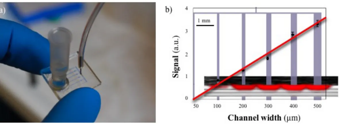
3.1.1 MICROFLUIDIC PHANTOMS. 33
3.1.2 CONCLUSIONS. 35
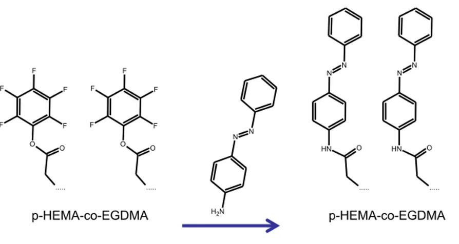
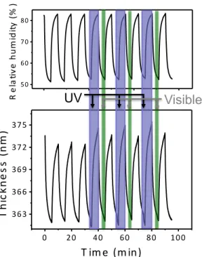
3.2 NOVEL LIGHT-RESPONSIVE BIOCOMPATIBLE HYDROGELS PRODUCED BY
INITIATED CHEMICAL VAPOR DEPOSITION. 36
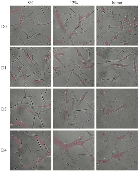
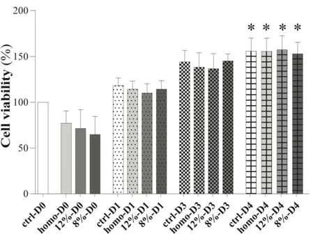
3.2.1 HYDROGELS CYTOCOMPATIBILITY TESTS. 39
3.2.2 CONCLUSIONS. 42
3.3 MATERIALS AND METHODS. 43
3.3.1 MICROFLUIDIC PHANTOMS. 43
3.3.2 GOLD NANORODS. 43
3.3.3 HYDROGEL SYNTHESIS AND CHARACTERIZATION. 44
3.3.4 CELL CULTURE AND VIABILITY TESTS. 45
3.3.6 STATISTICAL ANALYSIS. 45
4 INTERMEDIATE MOLDS FOR NANOIMPRINT LITHOGRAPHY. 47 4.1 PFPE INTERMEDIATE MOLDS FOR HIGH-RESOLUTION THERMAL NIL. 47
4.1.1 PFPE INTERMEDIATE MOLD: FABRICATION PROTOCOL. 50
4.1.2 PDMS AND PFPE AS INTERMEDIATE MOLD: A PERFORMANCE COMPARISON. 51 4.1.3 COCTHERMAL NANOIMPRINTING VIA PFPEINTERMEDIATE MOLDS. 52
4.1.4 CONCLUSIONS. 56
4.2 MATERIALS AND METHODS. 57
4.2.1 MOLD FABRICATION. 57
4.2.2 PDMS INTERMEDIATE MOLD FABRICATION. 57
4.2.3 PFPE INTERMEDIATE MOLD FABRICATION. 57
4.2.4 COC NANOIMPRINTING. 58
4.2.5 PET REPLICAS. 58
4.2.6 SCANNING ELECTRON MICROSCOPY. 58
4.2.7 CONTACT ANGLE MEASUREMENTS. 58
4.2.8 ATOMIC FORCE MICROSCOPY. 59
4.2.9 STATISTICAL ANALYSIS. 59
5 INTERACTION BETWEEN CELLS AND NANOTOPOGRAPHIES. 60 5.1 MULTI-SCALED STRUCTURED GERMANIUM NANORIPPLES AS TEMPLATES FOR
BIOACTIVE SURFACES. 60
5.1.1 GERMANIUM SAMPLE CHARACTERIZATION. 61
5.1.2 FABRICATION AND CHARACTERIZATION OF PET RIPPLED SURFACES 62
5.1.3 CELL SPREADING AND VIABILITY TESTS. 67
5.1.4 CELL MORPHOLOGICAL ANALYSIS. 69
5.1.5 ACTIN CYTOSKELETON ORGANIZATION ANALYSIS 73
5.1.6 CONCLUSIONS. 75
5.2 NEURONAL CONTACT GUIDANCE AND YAP/TAZ SIGNALING ON ULTRA
-SMALL NANOGRATINGS. 76
5.2.1 ULTRA-SMALL THERMOPLASTIC NANOGRATINGS. 78
5.2.2 NEURITE CONTACT GUIDANCE 80
5.2.3 FOCAL ADHESION MATURATION IS MODULATED BY ULTRA-SMALL
NANOGRATINGS 82
5.2.4 PHARMACOLOGICAL TUNING. 88
5.2.5 YAP/TAZ SIGNALING. 89
5.2.6 CONCLUSIONS. 93
5.3 MATERIALS AND METHODS. 94
5.3.1 FABRICATION PROCESSES. 94
5.3.2 SURFACE CHARACTERIZATIONS. 96
5.3.3 CELL CULTURES. 98
5.3.4 CELL ANALYSIS AND TESTS. 99
6 FUTURE PERSPECTIVES. 106
6.1 INTRODUCTION. 106
6.2 RATIONAL DESIGN OF NOISY TOPOGRAPHICAL GRADIENTS. 108
6.3 FABRICATION OF THE NOISY TOPOGRAPHICAL GRADIENTS ON SILICON
WAFERS. 111
6.4 SINGLE-CELL STUDIES 113
6.5 CONCLUSIONS. 115
6.6 MATERIALS AND METHODS. 117
6.6.1 FABRICATION PROCESSES. 117
6.6.2 CELL CULTURES. 118
6.6.3 LIVE-CELL MICROSCOPY AND IMAGE ANALYSIS. 118
7 CONCLUDING REMARKS. 119
8 LIST OF PUBLICATIONS. 122
9 LIST OF ACRONYMS. 123
1 Abstract.
Although peripheral nerves display regenerative abilities compared to the central nervous system, regeneration after centimeters nerve loss is very limited. To date, peripheral nerve injuries represent a major cause for morbidity and disability in the affected patients. Severe nerve lesions might occur at any age and result from many different types of traumas. In particular, young males are often involved in peripheral nerve injuries after car accidents and traumatic limb amputations. The incidence of peripheral nerve injuries lies at about 300,000 cases per year in Europe: the socio-economic impact is therefore high, comparable to diseases such as diabetes (European Commission report, 2016). Moreover, peripheral nerve lesions result to be clinically relevant with an incidence of 2/100,000 persons per year, value recorded only for hand amputation traumas. Hence, there is a considerable need for innovative therapies in the area of repair and regeneration of peripheral nerve injuries.
Nowadays, functional recovery after a nerve injury is achieved through the regeneration of the severed axons and the reinnervation of target tissues. In particular, nerve regeneration is fostered by a set of phenomena at the cellular level that recreate the connection from the proximal up to the distal stump. Nonetheless, a number of factors can interfere with functional recovery, hindering the complete healing of denervated target tissues.
In this context, tissue engineering can substantially enhance the repair of neural tissues through the use of artificial scaffolds. Although standard micro- and nanofabrication techniques have been employed to produce biomimetic scaffolds during the last two decades, it is still difficult to recreate the physiological complexity in an in vitro system.
The results reported in this thesis include novel nanofabrication techniques and materials for mechanotransduction studies and tissue engineering applications. In particular, the main topic of my Ph.D. project concerns the development and use of innovative biomaterials and nanoimprint lithography schemes for biomedical applications.
The current work is organized as follows. After this introduction (Chapter
1), I will provide a comprehensive overview of the current literature on engineered
polymers, identifying the key-features that make them leading candidates to regenerative medicine applications.
In particular, I will focus on fabrication techniques, mechanotransduction processes, peripheral nerve regeneration and neural scaffolds technologies, and nanostructured scaffolds (Chapter 2).
In Chapter 3 I will show the fabrication of novel microstructured phantoms to mimic vascularized tissues for photoacoustic system optimization. I will also investigate the possible use of novel light-responsive hydrogels for biomedical applications. Both of these studies will have the final aim of characterizing novel materials before their in vivo experimental tests.
Chapter 4 will be dedicated to the development and use of high-resolution intermediate molds for nanoimprint lithography (NIL). In this section I will detail the
optimization of perfluoropolyether (PFPE) as a soft mold for NIL, proving enhanced resolution and fidelity of the replica process.
In Chapter 5 I will demonstrate the applicability of PFPE intermediate molds for the fabrication of transparent and biocompatible cyclic olefin copolymer (COC) and polyethylene terephthalate (PET) scaffolds, patterned with two original types of sub-100 nm topographies, named nanoripples and nanogratings.
Preliminary results on topographical gradients of directionality will be reported in Chapter 6. I carried out this research activity mostly at ETH in Zurich, where I have been involved firsthand in the design of novel micropatterned structures as well as their fabrication, and in vitro cell migration assays.
Finally, in Chapter 7 I will summarize my research achievements, highlighting the contribution of the present work to the complex issue of peripheral nerve regeneration, and their potential for a medium-term clinical translation.
2 Engineered polymers for regenerative medicine
applications.
Regenerative medicine is an emerging multidisciplinary field that aims to restore, maintain or enhance tissues and hence organ functions. Regeneration of tissues can be achieved by the synergistic activity of living cells, which will provide biological functionality, and materials, which act as scaffolds to support cell proliferation.
Mammalian cells behave in vivo in response to the biological signals that they receive from the surrounding environment, which is structured by nanometer-scale components. Therefore, materials used for repairing the human body have to reproduce the correct signals that guide the cells towards the desired behavior. Nowadays, the interest in nanomedicine keeps growing because the application of nanotechnology tools to the structure development at the molecular level improves the interactions between material surfaces and biological entities. Although cells have micrometer dimensions, they evolve in vivo in close contact with the extracellular matrix (ECM), a three-dimensional network of extracellular macromolecules, which constitutes the topographical and structural features of nanometric size. The interactions between the cells and the ECM influence the cell growth, guide the cell mobility and affect the general behavior of cells. Nanotechnologies provide the possibility to fabricate surfaces, structures and materials with nanoscale features that can mimic the natural environment of cells and promote functions, such as cell adhesion, motility and differentiation.
In this chapter I will focus on aspects of nanotechnology relevant to biomaterials science. Specifically, the fabrication of polymeric materials, such as scaffolds for tissue engineering (TE), and the surfaces nanopatterning techniques aimed at eliciting specific biological responses from the host tissue will be addressed. Then, after a brief description of current scaffolding approaches in nerve grafts, I will highlight the role of nano-engineered biomaterial in preliminary in vitro studies for nerve regeneration process fulfillment.
2.1 Selected micro and nano-fabrication techniques for biocompatible
materials.
The development of nanotechnology is based on the study of fabrication techniques capable of producing nanometric-size structures rapidly and precisely [1], [2]. In fact, nanofabrication is the process of making functional structures with patterns having minimum dimension lower then 100nm [3], [4], [5].
Normally, fabrication methods used to develop micro and nanostructures are labeled as top-down and bottom-up, according to the process involved [4], [6]. In the bottom-up approaches the surface is structured by the self-assembly of small building blocks such as copolymers, micelles or particles [3]. While these methods afford the large-scale production of monodisperse devices with sub-micrometric size, controlling size, shape, structure and defects on the final devices is not a trivial task. To avoid these limitations, top-down methods were introduced.
Top-down processes aim at creating nanoscale structures with the desired shape starting from large blocks and reducing their size in a controlled way until the required scale is reached [5]. Photolithography and electron beam lithography, hot embossing and nanoimprint lithography are examples of top-down approaches [3].They have shown a great potential in patterning nanostructures, especially ordered arrays [6].
In this section, I shall illustrate top-down approaches to fabricate biocompatible nanostructures, introducing several powerful non-conventional lithographic methods. 2.1.1 Soft lithography patterning techniques.
In order to develop biocompatible nanometric features at low cost and overcome some limits of the conventional lithographic methods, new patterning techniques have been explored and developed. All those methods use a patterned stamp, mold or mask to generate polymeric micro/nano patterns or micro/nanostructures [7]. These methods are generally referred to as soft lithography techniques, and they have been developed as an alternative to conventional lithography. In fact, soft lithographic techniques are low in capital costs, straightforward to apply, easy to learn. Furthermore, they can generate patterns on non-planar surfaces and can be used with a variety of materials [7].
Examples of these techniques are Micro-contact printing, Micro-molding in capillaries, micro-transfer molding, replica molding, hot embossing.
Micro-contact printing (µCP) [8] is a soft lithographic method which employs
a micro/nanopattern elastomeric stamp, typically made in poly (dimethyl siloxane) (PDMS), with a chemical ink capable of forming patterns of self-assembled monolayer (SAMs) by contact with the target substrate [9]. Although µCP is extremely useful for a wide range of applications, it suffers from the limited resolution in reproducing features in the sub-micron range (from 1 µm to 100 nm).
Replica molding (REM) [10] [11] enables faithful duplication of three-dimensional topologies with feature size ≥ 100 nm in a single-step using PDMS molds. They are prepared by casting against rigid masters using a procedure similar to that used in µCP. The relief features on the PDMS mold can, in turn, be faithfully replicated by using this structure as a mold for forming structures in a second ultraviolet (UV)-curable (or thermally curable) prepolymer [10]. The use of an elastomeric mold, rather than a rigid one, simplifies the separation between the replica and the mold. Furthermore, its use reduces the possible damage of the initial mold and it enables faithful duplication of complex microstructures in multiple copies in a simple and inexpensive way [12], [13]. Although µCP and REM are extremely useful for a wide range of applications, particularly for the biomedical ones [14]–[16], their employment in the sub-micron range is hampered by resolution limits. Moreover, stamp deformation during its detachment from the template and during the patterning of the new substrate represents a severe hurdle to the widespread use of these techniques [17],[18]. Additionally, almost all organic solvents induce PDMS swelling, thus changing the feature dimensions [19].
Micro-molding in capillaries (MIMIC) and micro-transfer molding (mTM) are
other two soft lithographic techniques which exploit the conformal contact between a PDMS mold and a support to create a network of microstructures.
In the MIMIC case [20], the PDMS mold is placed on the surface of a substrate, forming a network of empty channels. Then, a low-viscosity prepolymer is placed at the open ends of the channels, and this liquid spontaneously fills the channels by capillary force. After curing the prepolymer, the PDMS mold is removed, leaving the patterned microstructures. Interestingly, the very slow filling
for very small capillaries limits its usefulness to structures with a width lower than 2 mm.
In mTM [7], [21], a drop of liquid prepolymer is applied to the patterned surface of a PDMS mold and the excess liquid is removed by scraping with a flat PDMS block or by blowing off with a stream of nitrogen. The filled mold is then placed in contact with a substrate and light radiated or heated. After the liquid precursor has cured to a solid, the mold is carefully peeled away to leave a patterned microstructure on the surface of the substrate. The most significant advantage of mTM over other microlithographic techniques is the ease with which it can fabricate microstructures on nonplanar surfaces, a characteristic that is essential for building three-dimensional microstructures layer by layer.
Although using mTM it becomes possible to obtain multilayer structures and to pattern 100 nm wide features, mold deformation is one of the main challenges that can be encountered. For example, the prepolymers are mainly organic and aqueous materials that must be removed when the liquid is converted into a solid. During the drying and sintering process, the thin film may diverge from the original shape due to shrinkage [22]. For similar reasons, closed loop structures cannot be replicated by microtransfer molding in one single step. This is because as the elastomeric resin pours over the loop and is cured, the loop ends up becoming topologically locked in the elastomer, being unable to be released [23]. Layer by layer fabrication approaches are thus necessary to mold closed loops via microtransfer molding.
2.1.1.1 Hot embossing.
Hot embossing of thermoplastics is a cost-effective replication technology to transfer nano/microstructure patterns form a master mold onto a thermoplastic material at set pressure and temperature [24], [25]. In fact, the process is composed by two major steps: heating the mold and the thermoplastic substrate to embossing temperature (i.e. above the glass transition temperature Tg of the thermoplastic polymer) and cooling down to demolding temperature [26], [27]. A thermoplastic material experiences the glassy state, rubbery state and flow state at increasing temperature [28], [29], as shown in Figure 2.1. When the operating temperature is
below Tg (glassy state), the deformation given by pressure is ideally elastic [30]. As
the temperature goes up (i.e. above its Tg and below its melting point Tf), the
thermoplastic polymer acts like an incompressible rubber and it softens reversibly when heated, but hardens when cooled back [31]. Finally, with a further increase of temperature, the viscous flow state can be reached and the deformation is thus irreversible in the flow state [28], [29]. Hot embossing is carried out between Tg and
Tf.
Figure 2.1 Thermoplastic polymers behavior vs. temperature in three states: glassy state, rubbery state and flow state. The figure is reported from [25].
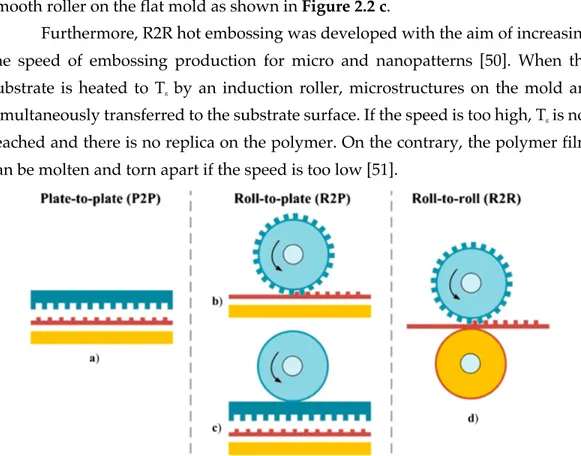
By simply changing the disposition or the shape of the molding tool, three different forming principles of micro hot embossing can be distinguished:
plate-to-plate (P2P), plate-to-plate-to-roll (P2R), roll-to-roll (R2R) (Figure 2.2).
Among these, P2P is the most conventional method, which contains a mold plate with micro or nanostructures and a substrate plate (Figure 2.2 a). Thanks to the high accuracy and controllability of this process, P2P is widely used for industrial production of compact disc (CD) and digital versatile disc (DVD), as examples. In fact, as relatively mature technology, P2P apparatuses are commercially available and sold by industries as Jenoptik Mikrotechnik GmbH, Wickert Press, Evgroup, SUSS Microtec, Karlsruhe Institute of Technology and Obducat AB [32]–[37].
Nevertheless, P2P is a discontinuous batch-wise mode facing drawbacks of limited efficiency and in some cases rather small replication areas [38], [39]. Moreover, the fabrication of patterns with high aspect ratio (i.e. ratio between
and distorted features. In fact, thermal contraction of polymers is significantly different from that of the molds, usually fabricated in hard materials such as silicon or nickel. As a result, if the cool-down step is not optimized, the thermal capacity mismatch between the two materials generates a large thermal stress during demolding, thus making it difficult to separate polymeric features from the mold. It was demonstrated by Dirckx’s group [40] that both adhesion and sidewall friction played a fundamental role in demolding. In particular, coatings such as amorphous silicon carbide and Teflon-like fluoropolymer reduce demolding energy [41]. Unfortunately, long cycle time for heating and cooling as well as low pattern uniformity for very large-areas are unsolved problems that compromise in some cases the overall success of P2P technique. To solve those issues, rubber-assisted
embossing, ultrasonic-vibration and gas-assisted embossing strategies were introduced.
Briefly, in rubber-assisted embossing [42], [43], the thermoplastic film is pressurized between the hard mold surface and a rubber pad, performing the desired conformal contact process.
Ultrasonic-vibration embossing is based on intermolecular friction at the
interface between the mold and the imprinted material [44], [45]. Compared with conductive or convective heat transfer, this fabrication method results faster and more efficient.
Recently, gas pressure has been introduced as load during hot embossing (gas-assisted embossing) to generate uniform pressure over large areas [46], [47]. It was proved that it is possible to fabricate uniform micro/nanostructures on large polymeric area, up to 18 cm2 [48].
Therefore, compared to other conventional processes, the hot embossing enables fine-pattern processing using only a stamp. Owing to these advantages, studies on hot embossing have been widely conducted. As example, differently from P2P, where the entire polymer is imprinted simultaneously after heating above Tg, in P2R only the small area in contact with the roller has a temperature higher than Tg, as shown in Figure 2.2 b. Moreover, molding and demolding steps are continuously performed, so that the process efficiency depends from fabrication parameters such as imprint pressure and rolling speed, as well as temperature. Normally, features with low aspect ratio imprinted on a low-viscosity polymer have
configuration relies on putting a flat mold directly on a substrate and rolling a smooth roller on the flat mold as shown in Figure 2.2 c.
Furthermore, R2R hot embossing was developed with the aim of increasing the speed of embossing production for micro and nanopatterns [50]. When the substrate is heated to Tg by an induction roller, microstructures on the mold are
simultaneously transferred to the substrate surface. If the speed is too high, Tg is not
reached and there is no replica on the polymer. On the contrary, the polymer film can be molten and torn apart if the speed is too low [51].
Figure 2.2 Schematic diagrams of three modes of micro hot embossing. The schematic of P2P hot embossing is illustrated in a) which contains a micro/nano-structured mold and a substrate plate. b-c) R2P, characterized by a rotation cylinder and a flat plate, is proposed to meet the increasing demand for large-area patterned polymeric films. There are two typical R2P modes: b) rolling a cylindrical micro/nano-structured mold on a flat and solid substrate, or putting a mold in contact with a substrate and rolling a smooth roller on the system, as shown in c). d) The continuous and high-throughput fabrication method for patterned polymeric films is R2R hot embossing, characterized by two rollers with a polymer film in between. The figure is reported from [25].
In order to overcome some limits of the conventional hot embossing techniques as high replacement costs for mold pattern change, Yun and coauthors [52] proposed an impact-imprint type hot embossing technique. This new embossing method requires a fine-shaped printing head which applies force onto a heated substrate. The pattern is fabricated by controlling the position of the printing head, dot by dot. The main advantage of this technique is that various patterns can be embossed in real-time but, on the contrary, a mismatch in size of 7 % between final pattern and printing head is observed.
2.1.1.2 Nanoimprint Lithography.
Thermal Nanoimprint Lithography.
In literature, hot embossing and NIL are often used with the same meaning, particularly when the replicated patterns bear sub-micrometric dimensions. The plausible difference between hot embossing and NIL is the thickness of the polymer to be structured: thanks to hot embossing, a bulk material is nanostructured directly on its surface, while NIL process involves the use of a thin thermoplastic film or resist [53], [54].
In particular, for thermal NIL, the fabrication principle is based on a nanopatterned hard mold employed to deform a thermoplastic polymer under controlled pressure and temperature, as shown in Figure 2.3. The increased polymer temperature reduces the viscosity of the material, so that the applied pressure helps the molten polymer to flow into the cavities. As in a standard hot embossing process, the final cooling of the system freezes the pattern on the target surface, thus providing a negative copy of the master.
Figure 2.3 Schematic diagram of a NIL process. Yellow curve: set temperature, red curve: measured temperature. Green curve: set pressure, cyan curve: measured pressure.
With such technique, Chou et al. [53] achieved a minimum resolution of 25 nm in patterning holes of 25 nm in diameter, spatially separated by a distance of 95 nm,
on a poly(methyl methacrylate) (PMMA) film. More recently, Schvartzman et al [55] imprinted PMMA pillars of 10 nm in diameter.
One of the major challenges related to this technique is the mold lifetime. NIL molds have to be replaced after ~ 50 consecutive imprints or less. In fact, high pressure and heating and cooling cycles cause stress and wear to NIL molds. In particular, the mold can be damaged by polymer attachment on its surface during the imprint process.
To solve this issue, two different methods have been introduced: a hydrophobic coating on the mold surface (i.e. silane coating), and the use of hydrophobic polymeric molds, such as PDMS [56], [57], ethylene tetrafluoroethylene (ETFE) [58], [59], or PFPE, as I did in [60], [61].
Hydrophobic coating is the standard technique for preserving the integrity of hard molds and polymeric replicas, and for minimizing defects on both surfaces. Furthermore, the remarkable thinness of silane coating (< 2 nm) fosters a strong bonding of the coating onto mold surface [62]. On the other hand, mold breakage remains a problem during the demolding step. In fact, after the NIL process, the rigidity of the hard mold makes it very difficult to clearly separate it from the substrate. Conventionally, a scalpel or a razor blade have been employed to separate the mold from the substrate, but if the detaching procedure is not properly executed, it might introduce mold surface damages and cracks [56].
2.1.1.3 UV-Nanoimprint Lithography.
The ultraviolet NIL (UV-NIL) process has several prominent advantages over the thermal NIL, including the capability of U-NIL to be conducted at room temperature without the need of elevated temperature imprinting. Therefore, this helps to eliminate the issues resulting from thermal expansion variations between the mold, substrate and polymeric resist [3], [63].
In particular, an optically transparent mold (made of quartz, indium thin oxide or other UV-transparent materials) [64] is pressed into the polymeric solution at room temperature, and then the solution is polymerized by UV irradiation. Due to the typical low viscosity of the resist, a pressure of few bars (1-5 bars) [65] is sufficient to perform the imprint process. Acrylate formulations are very often used
in UV-NIL processes because of their commercial availability, low viscosity and rapid photopolymerization. On the other hand, the use of acrylates requires an inert atmosphere, since oxygen is a strong radical inhibitor for this process [66]. While UV-NIL offers several advantages, it is important that many parameters such as polymerization time, surface energy of the mold and polymer transparency are carefully evaluated, as they can critically affect the replication and demolding processes. Furthermore, shrinkage is an important factor to be optimized in order to avoid replica cracking during demolding. In fact, during UV curing, the resist volume shrinks. Thanks to a ring opening polymerization, epoxy resist has a very limited shrinkage rate, in general ~ 3 %. On the other hand, acrylates and vinyl-ether resists show shrinkage rates of ~ 10 %. Indeed, due to the thin residual resist thickness and the mechanical rigidity of the substrate, the bottom of the fabricated structures is not able to relax. Consequently, the resist shrinkage will induce a change in the top lateral dimensions and height of the features, reducing their lateral slope. In order to limit the shrinkage, resist formulations are made with monomers presenting a reduced shrinkage. Hence, steric hindrance might be used. Another possibility is to include an oligomer or a polymer in the resist formulation as a binder, but taking into account the increased resist viscosity [67]. In addition, insufficient UV irradiation might cause distortion and structure collapse [68].
2.1.1.4 Step-and-Flash and reverse Nanoimprint Lithography.
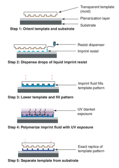
Step and Flash nanoImprint Lithography (SFIL) is considered to be one of the most promising alternatives to conventional soft lithography techniques. SFIL uses a low viscosity monomer (<5 cPs) that is dispensed as droplets deposited on the substrate, rather than as a spun-on film (Figure 2.4) [69].
Figure 2.4 Schematic illustration of SFIL process. Drops of a low-viscosity monomer are deposited onto the substrate and contacted with the transparent mold, causing the drops to spread, merge and fill the mold. The monomer is UV exposed, and the mold is separated, leaving a replica of the mold pattern. The figure is reported from [70].
A transparent quartz mold with relief nanostructures contacts the monomer, and the drops spread, merge and fill the features in the mold. The monomer is then exposed to UV light via backside illumination, and the patterned structure is left on the substrate when the mold is removed. This process uses the lowest imprint pressures possible (~2 bar), so the low viscosity resists readily flow to fill the recesses of the mold. SFIL offers the opportunity of modifying the material chemistry, drop by drop, when creating the surface pattern.
The advantages of SFIL include feature resolution (limited only by template fabrication), large patterned areas, high throughput, process easiness and
robustness, room temperature and low-pressure processing conditions, device manufacturing costs reduction.
The main drawback is instead the pattern peeling from planarization layer, caused by the demolding process [71]. One successful strategy to avoid the pattern peeling is to reduce the mold surface energy with respect to the substrate one, exploited also for reverse nanoimprinting. Simply, the polymer is spin-coated onto a transparent mold instead of the planarization layer, filling areas of surface relief patterns, then transferred on the planarization layer by one of the NIL techniques [29]. This last technique is particularly useful to transfer patterns on substrates that are not suitable for spin coating [72].
2.1.1.5 Nanoimprint by Melt Processing.
The key difference between nanoimprint by melt processing (NIMP) and thermal NIL is that the NIMP process uses low-viscous plasticized polymers in the flow state (as shown in Figure 2.1). In the case of NIL, a high-molecular weight polymer is often spun on substrate, then heated to a temperature higher than Tg of the
thermoplastic polymer. After the highly viscous polymer has reached the set temperature, the polymer is patterned by pressing the hard mold onto its surface, under high pressure.
The NIMP process begins with a low-molecular weight polymer mixed with a proper plasticizer, chosen for its compatibility with the low-molecular weight polymer and processability. The mixture is suddenly deposited on a base-plate, similarly to the drop of UV curable resist placed on substrate, in the case of UV-NIL. Then, the base-plate temperature is increased so that the polymer melts completely to form a low-viscosity drop.
Owing to the low viscosity of the polymer drop, the pressure required for replica process is typically ten times less than in thermal NIL (~ few bars) and comparable to the one employed for SFIL process. In addition, the lifetime of the mold is much longer, compared to a thermal NIL, since the required pressure is an order of magnitude lower than the standard replica process [52], [65].
2.1.2 Initiated Chemical vapor deposition polymerization (iCVD).
Nowadays chemical vapor deposition (CVD) is widely applied in microelectronics, optoelectronics and energy conversion industries [73], [74], [75] to produce inorganic thin films and materials, carbon nanotubes and graphene sheets [76], [77]. More recently, CVD was employed also to fabricate and engineer polymeric thin films or hydrogels (i.e. polymeric networks that take in and store a considerable amount of water).
In fact, what it is called initiated chemical vapor deposition polymerization (iCVD) foresees that volatile monomers and an initiator molecule flow inside a temperature- and vacuum-controlled chamber, as in a standard CVD process. Therefore, the initiator molecule forms radicals, which react with the monomers on the cooled substrate by thermal decomposition [78], UV radiation [79], or plasma treatment [80]. Finally, the CVD polymer forms on the cooled substrate [81]. The iCVD process operates at low surface temperatures (ranging from 20 to 60 °C), promoting monomers absorption on the substrates [82]. The relatively low temperature of the iCVD process is particularly suitable for easily functionalizing hydrogel surfaces, as their chemical structure is fully retained [83].
2.2 Nanotopographies for mechanotransduction studies.
Nowadays, nanotechnology and the related fabrication techniques ensure the fabrication of biocompatible interfaces, the extracellular matrix (ECM), that can reproduce the biomechanical cues that are required for tissue morphogenesis, differentiation and homeostasis. In particular, the microfabrication and nanolithography techniques mentioned in the previous section ensure the development of micrometric and sub-micrometric features on biocompatible materials that can be employed as scaffolds in different tissue regeneration fields.
In this section I shall introduce tissue engineering (TE) as a combination of engineering methods, materials and biochemical factors to heal or replace a biological tissue. Then, I will thoroughly discuss the role of ECM in the mechanosensing and mechanotransduction processes, with a highlight on its interaction cells.
In the following, I will briefly review scaffold approaches for TE applications. Starting from the requirements that scaffolds have to provide to mimic the ECM functions, I will then provide a concise presentation of the synthetic and the natural materials already employed as TE scaffolds, together with the latest developments in this field.
2.2.1 Tissue engineering.
TE is continuously expanding thanks to the interaction between different research fields such as biology, chemistry, material science, nanotechnology and to the development of novel micro-nano fabrication techniques [84]. The ultimate aim is the implantation of constructs (i.e. scaffolds) into the body not only to repair an injury but, in some cases, to replace the function of a failing organ [85].
TE materials have to be as similar as possible to the original environment, in order to mimic tissues for research purposes and that can help regeneration of injured tissues. Regenerative medicine is often used as a synonymous of TE, although regenerative medicine implies the use of stem cells to heal or replace the injured tissue [86].
2.2.2 The role of ECM in mechanosensing and mechanotransduction.
functions including providing not only physical sustain and spatial organization to the tissue, but also mechanical and chemical cues to cells [87],thus promoting their proliferation and differentiation [88].
In nature, tissues are composed by both cellular and acellular components: the acellular ones are referred to as ECM. In fact, the structure and composition of ECM widely vary between different tissue types, but the leading components of ECM remain proteoglycans, collagen, laminin and fibronectin proteins. In particular, these proteins are organized in folded domains whose sequences are highly preserved. The cells adhesion receptors, e.g. the integrins, bind folded domains, thus controlling cell-matrix interaction and transducing signal to cell cytoskeleton [89], [90]. Due to their major role in mechanosensitive processes, the cell-matrix complexes have been studied thoroughly. In fact, integrins, zyxin, talin, vinculin, Src, and focal adhesion kinase, the core components of focal adhesion (FA) complexes, deeply influence actin polymerization, cell migration and differentiation [91], [92].
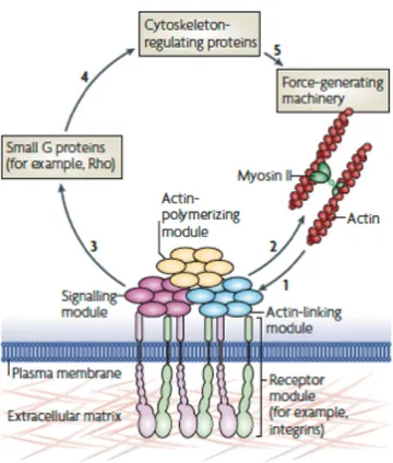
Figure 2.5 Focal adhesions: structure and function. Forces that are generated by actin polymerization and myosin II-dependent contractility (step 1) affect specific mechanosensitive proteins in the actin-linking module (talin and vinculin), the receptor module (represented by integrins, and co-receptors, the associated actin-polymerizing module (for example, zyxin) and the signalling module (represented by, for example, focal adhesion kinase). Acting in concert, these interacting modules, with their particular mechanosensitive components, form a mechanoresponsive network. The effect on the actin cytoskeleton (step 2) depends on the integrated response of the entire system to interactions with the matrix and to applied mechanical forces. Stimulation of the signaling module eventually leads to the activation of guanine nucleotide-exchange factors and GTPase-activating proteins, leading to activation or inactivation of small G proteins, such as Rho and Rac (step 3). These G proteins affect actin polymerization and actomyosin contractility through cytoskeleton-regulating proteins (step 4), thus modulating the force-generating machinery (step 5). The figure is reported from [93].
As depicted in Figure 2.5, FAs are intersection nodes where the environmental mechanical signals are transduced to intracellular forces and chemical signals through cytoskeletal connections and signaling proteins [94]. In fact, actin cytoskeleton and actin-associated proteins change their physical properties in response to a mechanical stimulus, as in the case of their application on actin network, which can influence myosin and actin activity [95]. Notably, mechanotransduction at FA level is bidirectional: forces are both transduced from
transmembrane adhesion receptors are the primary mechanosensors at FAs level: once a force is applied, FAs change their state from bent to extended, increasing their affinity for ECM ligands [97].
Besides the well-described role of integrin-mediated adhesion in the regulation of cell proliferation, the mechanotransduction process is not just limited to cytosol, yet it comprises also cell nucleus. Among others, the Hippo signaling pathway has emerged as a critical effector process by which changes in cell tension affect cell proliferation [98]. Hippo pathway activation leads to the nuclear exclusion of the mechanosensitive transcriptional activators, namely Yes-Associated Protein (YAP) and the transcriptional coactivator (TAZ) [99]. In fact, both cell shape and substrate stiffness control Hippo signaling activity, simply by the formation of stress fibers in response to an alteration in substrate stiffness. However, this mechanism is still not well understood.
In recent years, it has become increasingly clear that cellular responses to external signaling cannot be merely determined by the sensing of chemical ligands on ECM, but a wide range of physical cues must also be taken into account [93].
2.2.2.1 Substrate topographies.
Since natural tissues are composed by sized biomolecules and ECM nano-cues, all features with typical dimension around 500 nm or smaller (e.g. nanoparticles [100], nanofibers [101], nanogratings [102]) can closely mimic native biological systems, helping cell growth and tissue regeneration.
In 1912 Harrison was the first to show that cell shape and migration were strictly linked to substrate topography [103]. Later, Weiss [104] showed that cells can move and migrate by contact guidance mechanism (i.e., cell-shape adaptation to
the local extracellular environment [105]).
Since then, many studies were conducted to clarify the cell-substrate interactions on patterned substrates, using different materials, features and cells [106], [107], [108].
Particularly, topographical factors as size, shape and geometry of the single feature can exert strong effects on many cells' behaviors, such as adhesion, migration, alignment and differentiation [109], [110], [111].
Although it is well known that the cell response to topography is strongly dependent on cell type, the influence of topographical size (in terms of width, spacing and depth of features) was found for many cell types. Micro- and nano-topographies regulate the whole cell morphology and spatial distribution, as well as in the subcellular sensing mechanisms [112].
Scaffolds engineered with mimicked-natural topography have been tested to rebuild tissues in vitro, such as corneal substitutes [113] and vascular graft [114].
2.2.3 Scaffolding approaches in TE.
Since the role of scaffolds in TE is analogous to the ECM functions in native tissues, and those functions are linked to their architectural, biological and mechanical features, a TE scaffold satisfies at least one the following properties: Biocompatibility: cells must adhere and migrate along the surface and potentially through the scaffold. Moreover, the scaffold must avoid any immune reaction that can reduce healing process or cause rejection by the body [115];
Biodegradability: neither the scaffold material nor its degradation products should provoke inflammation or toxicity when implanted in vivo [116];
Porosity: the interconnected pore structure and high pore density ensure the cellular penetration and the adequate diffusion of nutrients to cells. Scaffold porosity also helps diffusion of cell waste and scaffold degradation products out of the scaffold itself. Moreover, cells interact with scaffolds via chemical groups (i.e. ligand, as Arg-Gly-Asp, the RGD sequence), therefore synthetic pores have to lead a minimal ligand density to allow cell binding [117];
Mechanical properties: the engineered scaffold should have mechanical properties matching the ones of the host tissue and must allow surgical handling during implantation [118].
Over the last two decades, the scaffolding approaches for TE have significantly evolved. In general, biomaterials for TE can be classified in two categories, according to their sources, namely synthetic and natural. However, the use of a decellularized ECM of a tissue is another promising trend, as well as cell sheets with
self-secreted ECM and cell encapsulation in self-assembled hydrogel matrixes, herein reported.
Synthetic scaffolds.
Although many synthetic biomaterials have a regulatory approval from Food and Drug Administration (FDA) for their employment in surgery [119], they were far from being the optimal choice for many TE purposes. In fact, their hydrolytic biodegradation releases acids that can be cytotoxic, as in the case of polylactic, polyglycolic and polycaprolactone [120].
One example of optimized synthetic scaffold is PuraMatrixTM (3DM,
Cambridge, MA), which is composed by synthetic nanofibers of oligopeptide fragments. This scaffold has customizable properties such as injectability, optimal porosity and resorption rates [121].
Natural scaffolds.
Natural scaffold materials can be obtained from their natural source and can be processed to enhance their natural porosity. Those materials can be in their native form, such as ECM from allograft or xenograft, or can be protein-based materials (e.g. collagen, fibrin) or polysaccharide-based materials (e.g. chitosan, alginate, hyaluronic acid) [122], [123]).
Despite their excellent biocompatibility, natural materials have a limited mechanical rigidity and durability over time: in literature there are several examples of reinforcing strategies, such as development of composites with synthetic materials [124] or photochemical crosslink of the scaffold [125].
Decellularized ECM matrix.
Nowadays, there is an increasing interest in using decellularized tissue matrices from allogenic or xenogeneic tissues, after the removal of antigens but preserving ECM components. Notably, ECM from decellularized tissues is exploited not only for replacing tissues with an analogous structure, as the vessels for the allogenic vascular grafts [126], yet also to replace tissues with different biological function with respect to the native one, as it happens with amnion membrane for peripheral nerve regeneration [127].
By the use of this technique, rapid advancements were obtained with heart, liver and lung tissues [128]. Nevertheless, the methods employed in recellularization of whole-organ scaffolds are typically adaptations of techniques from a wide range of procedures including traditional cell culture, tissue-engineering methods, cell-transplantation therapies. In particular, this process may also lead to an inhomogeneous distribution of the decellularized matrix and the complete removal of cell components may cause an immune response upon implantation [129].
Cell sheets with self-secreted ECM.
In this TE approach, cells secrete their own matrix on thermoresponsive polymers upon confluence and then their controlled detachment is obtained by temperature regulation, which modulates the hydrophobicity of the polymer. Cell sheet engineering method is excellent for epithelium, endothelium and cell-dense tissues [130].
For example, in order to fabricate a 300 µm myocardial patch, this method must be repeated ten times. In fact, each ECM layer is 30 µm-thick, so the main disadvantage of this technique is the fabrication yield [131].
Cell encapsulation in self-assembled hydrogel matrixes.
This fabrication technique combines the scaffold fabrication and cell seeding into a one-step procedure, because living cells are entrapped into the liquid biomaterials (e.g. agarose [132], chitosan [133], poly(ethylene) glycol [134] and polyvinyl alcohol [135]) before polymerization starts. The most famous applications of this fabrication
method is xenogenic pancreatic cell transplantation for diabetes [136]. Nevertheless applications for central nervous system and promising anti-angiogenic results with endostatin-transfected cells encapsulated in alginate for the treatment of malignant brain tumors [137] and liver failure [138], have also been reported in the literature [118].
2.3 Scaffolds for nerve regeneration.
Tissue engineered nerve grafts (TENGs) is an emerging approach alternative to the gold standard for peripheral nerve repair, the autologous nerve graft. In fact, spontaneous peripheral nerve repair is nearly incomplete with poor functional recovery, although the peripheral nervous system (PNS) has a greater ability of axonal self-regeneration if compared to the central nervous system (CNS) [139].
The nerve autografting remains the gold standard clinical treatment for peripheral nerve defects, but the main disadvantage of this method is the morbidity of the donor site, additional intra- and postoperative risks, the limited graft availability and the limitation of use in motor or mixed (motor and sensory), nerve defects [140]. Motor nerve grafts are more suitable for these situations, but the benefit does not surpass the disadvantage of sacrificing their initial function [141].
Nevertheless, the limitations of the autografts have led researchers to develop artificial neural scaffolds as replacements, and overall the artificial scaffold technology have demonstrated promising results. In particular, material scientists have contributed substantially to the sharpening of nerve regeneration processes, by the development of novel fabrication techniques, scaffold architectures and lumen surface modifications. Moreover, growth factor supplements, stem cell transplantation and cell surface glycoengineering could enhance the efficiency of the biomimetic features of neural scaffolds, thus working synergistically for nerve regeneration process fulfillment [142].
In this section I will briefly highlight the peripheral nerve anatomy and the role of Schwann cells (SCs) after an injury. I will then summarize commercial tubes already approved by the Food and Drug Administration (FDA) for human use. Starting from nerve guidance channel (NGC), considered as the most straightforward strategy for peripheral nerve regeneration, I will then provide a brief review of the synergistic use of the NGCs together with stem cells and growth factor supplementation, besides the use of the metabolic glycoengineering. In the last part of this section I will summarize the role of nanostructures in the PNS regeneration.
2.3.1 Peripheral nerves and Wallerian degeneration.
In fact, in the peripheral nervous system, bundles of nerve fibers or axons conduct information to and from the central nervous system. In myelinated nerve fibers, these axons are surrounded by a myelin sheath composed of concentric layers of SCs, helping to increase neuronal signaling speeds. Those nerve fibers are surrounded by connective tissues (endoneurium, perineurium and epineurium), capillaries and vessels, as shown in Figure 2.6.
Particularly, the endoneurium holds axons and SCs together, composing the endoneurium tube, which is surrounded by the connective tissue of perineurium. The perineurium, in turn, is made of collagen fibrils (type I and III) and elastic fibers interspersed between 15 layers of perineurial cells [143], [144]. Both endoneurium and perineurium have a basal lamina made of laminin, fibronectin and proteoglycans. Altogether, the endoneurial tubes, blood vessels and perineurium compose the nerve fascicles covered by the epineurium, with a thickness ranging from 1.3 to 100 µm [145].
Figure 2.6 Cross-sectional anatomy of the peripheral nerve. The left inset shows an unmyelinated fiber. The bottom inset shows a myelinated fiber. The epineurium is the connective tissue layer of the peripheral nerve. Its main function is to nourish and protect the fascicles. The outer layers of the epineurium are condensed into a sheath. Within and through the epineurium lie several fascicles, each surrounded by a perineurial sheath. The perineurial layer is the major contributor to nerve tensile strength. The endoneurium is the innermost loose collagenous matrix within the fascicles. Axons run through the endoneurium and are protected and nourished by this layer. The figure is reported from
The PNS has far greater regeneration potential than the central nervous system mainly due to the different response of the respective glial cells to injuries [147]. In fact, the SCs convert to a regenerative phenotype, thereby promoting the formation of a basal lamina and providing abundant cues to trigger neuronal regenerative response [144].
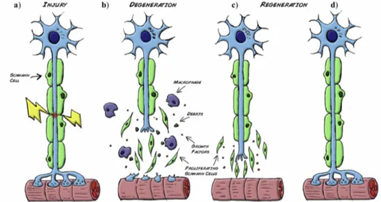
As depicted in Figure 2.7, the distal stump of the injured nerve undergoes a series of molecular and cellular changes known as Wallerian degeneration (Figure 2.7
a). Within a few hours, both the axon and the myelin in the distal stump degenerate
and macrophages migrate to the site of injury and contribute to debris clearance (Figure 2.7 b). In the first 24 h, SCs proliferate and switch from a myelinating to a regenerative phenotype and exhibit up-regulation of several molecules that assist the parallel degenerative and regenerative processes.
In particular, when the debris has been removed by the combined action of SCs and macrophages, SCs align forming columns called bands of Büngner (Figure
2.7 c). This forms a permissive environment rich in trophic factors, enabling guided
axonal regeneration (Figure 2.7 d) [148].
Figure 2.7 Wallerian degeneration. a) Following injury, b) Schwann cells detach from the axons, start proliferating and help the recruited macrophages to clear the cellular and myelin debris. c-d) At the same time expression of stimulating factors by SCs create a favorable environment for nerve regrowth towards the target organ. The figure is reported from [148].
2.3.2 Commercially-available devices and new engineered approaches for neural scaffolds.
In order to accomplish its role in TENGs, the neural scaffold are designed to guide and protect the injured nerve regrowth and to deliver biochemical cues [149].
To date, various bio-absorbable nerve tubes have been approved by US FDA for human use. Among them, it is worth mentioning the type I-collagen scaffolds
NeuragenTM, NeuroMatrixTM and NeuraWrapTM, the scaffolds based on poly(glycolic
acid) (PGA), such as NeurotubeTM, and those fabricated in
poly(D,L-lactide-co-e-caprolactone) (PLCL): NeurolacTM and NeuroMendTM.
Notably, NeuragenTM was the first to be commercialized (2001), it is available
in various inner diameters (1.5-7mm) and two different lengths (2 and 3 cm). Compared to more rigid materials (silicone), the NeuragenTM achieved results similar
to autograft [150], and it exhibited no compression neuropathy. Moreover, it remained intact up to 4 years post implantation [151]. For PGA-based tubes,
NeurotubeTM has an internal diameter of 2.3 mm, 4 and 8 mm and length of 2 cm or
4 cm. Its main employment is for digital nerve defects not exceeding 3 mm [152]. In the case of PLCL tubes, Secer and colleagues evaluated 455 patients with ulnar nerve injuries caused by gunshot wounds and treated with NeurolacTM.
They found that reinnervation time depends on the severity of the lesion and how far the proximal stump of the ulnar nerve is from the target muscles. Overall, the optimal recovery after the repair of gunshot-inflicted ulnar nerve injuries is strictly dependent on the entity of repair, the time frame from the injury to surgical operation (between 2 to 4 weeks post injury to allow the delineation of proximal and distal stump damage), the surgical approach, and the length of the graft [153].
Despite the promising results in human patients, tube swelling and auto mutilation incidents raised concerns about scaffolds biocompatibility and degradation rate tested on a black hooded rats of 10 mm-long gap injury [154].
2.3.3 Strategies for an enhanced peripheral nerve regeneration.
The transition from an engineered biomaterial to optimized neural scaffolds involves two correlated aspects, the scaffold configuration and fabrication, both of which significantly affect the performance of the final scaffold.
Initially, biomaterials were engineered into the simplest configuration, which is a hollow single tube. This scaffold was named NGC, which had an empty lumen. In order to improve the scaffold performance, NGC with an internal micro architecture or an internal multi-component composition within its lumen were fabricated. As an example, one or more intraluminal channels could be introduced to construct a multichannel NGC, thus mimicking the architecture of nerve bundles and reducing dispersion of regenerating axons [155]
Another exploited strategy to improve nerve regeneration is the inclusion of physical fillers into the NGC lumen to mimic the endoneurial structure, typical of autologous nerve grafts [156]. In literature a chitosan-based NGC and PGA intraluminal filaments were employed to bridge a 30 mm-long sciatic nerve gap in dogs, thus enhancing the ingrowth of blood vessels, guiding SCs and allowing diffusion of nutrients [157].
2.3.3.1 Synergy with other peripheral nerve regeneration strategies.
Although NGCs are the main technology for the restore of peripheral nerve activity, they have been shown to be effective only for lesions shorter than 10 mm in rats or 30 mm in primates. If used alone, the scaffold strategy was not successful for larger gaps. Schwann cells, neural stem cells, embryonic stem cells and marrow stromal cells have been the most studied support cells [158]. Moreover, growth factor supplementation, metabolic glycoengineering and modification of the cell surfaces can be also incorporated to optimize the peripheral nerve repair [159], [160].
Stem cell transplantation.
Stem cell transplantation is a widely used strategy for peripheral nerve regeneration. In fact, stem cells can secrete appropriate pro-regenerative factors. Promising examples of stem cell used in peripheral nerve repair are bone marrow mesenchymal stem cells and adipose-derived stem cells.
Bone marrow mesenchymal stem cells (BMSCs) are easily obtained through the aspiration of the bone marrow and expanded in large scale by in vitro culture. BMSCs have found increasing applications in cell-based therapies, including neural
allogenic SCs are involved in immunological reactions [161]. Therefore, BMSCs are becoming a promising alternative to SCs, showing a considerable success in experimental studies with the repair of 50 mm-long gap in dog sciatic nerves [162] and a 50-mm long median nerve gap in rhesus monkeys [163].
Adipose-derived stem cells (ADSCs) are superior to BMSCs in some aspects, from their harvesting to their availability. Either undifferentiated or differentiated ADSCs combined with neural scaffolds have bridged peripheral nerve gaps of different lengths, up to 1 cm rat sciatic nerve gap [164], [165], [166]. Pre-clinical studies have demonstrated the role of stem cell transplantation as successful therapy combined with traditional methods of peripheral nerve repair. However, current technologies have yet to identify optimized conditions for clinical use in terms of both efficacy and safety [167].
Growth factor supplementation.
The local presence of growth factors at the injurie sites can play a fundamental role in improving the peripheral nerve injury treatment. Their supportive action may be hindered by the obvious decrease over time of cellular production of growth factors, which makes it necessary the continuous exogenous supply of growth factors. The most commonly used growth factors include brain-derived growth factor, nerve growth factor and glial cell-brain-derived neurotrophic factor [168]. Moreover, these delivery systems ensure positive impacts on nerve reconstruction, in particular they enhance the adsorption of growth factors on the surface or bulk of the scaffold or the entrapment of growth factors during scaffold fabrication [168].
Several studies report different techniques to immobilize nerve growth factor (NGF) onto scaffolds, among which crosslinking is the most commonly used. In particular, genipin enhances crosslink yield in the case of a scaffold fabricated with chitosan and NGF, further processed into an NGC. After in vitro tests [169], an in
vivo study was subsequently reported where a 10 mm-long rat sciatic nerve was
Metabolic Glycoengineering.
A substantial enhancement in the nerve regeneration process can be achieved by improving the interaction between cells and scaffolds. This can be obtained either by acting on scaffolds morphology, or by modifying the biological behavior of the cells themselves.
Metabolic glycoengineering (MGE) manipulates the cell biosynthetic pathways of oligosaccharides and glycoconjugates by using sugar analogs [171]. In fact, altering glycans on cell surface may improve cell adhesion and differentiation [172]. Moreover, MGE technique has the ability to alter cell adhesion via the activation of integrins [173]; furthermore carbohydrate-based cell surface modification has been studied in vivo [174], demonstrating an improved peripheral nerve regeneration and unleashing its potential for clinical translation.
Nanostructured scaffolds for peripheral nerve regeneration.
As I have already mentioned, the in vivo interactions between scaffolds and host cells/tissues are complex and bi-directional: not only the scaffold elicits cell and tissue responses, yet also cells and tissues modify the local environment provided by scaffold itself, through the deposition of ECM molecules [175].
In order to better investigate those mutual interactions, nanoscale topographies were added on the neural scaffold surface. In fact, those nanometric features have the same size of the natural architecture of the ECM cues [176] [177] and induce contact guidance in nerve regeneration. Moreover, nano features promote the adhesion of the surrounding cells to scaffolds and the infiltration of neural and glial processes. Additionally, these features can be arranged to provide topographical cues to guide axons across large injury gaps [178].
As previously discussed, there are three different size scales to take into account for scaffold design: the functional tissue level (>100 µm), the cellular level (1-100 µm) and the subcellular-or nanostructured- one (<1 µm) [179].
Considering these three size scales in tissues, the nanostructured level is the less understood, but it is as relevant as the other two. As an example of nanostructures in PNS, the major ECM component is laminin, which exhibits a
eliciting interactions between gratings (anisotropic topographies composed of alternating ridges and grooves) and neural cells. The main goal of those studies has been to orient neurite outgrowth for the establishment of in vitro neural networks and the targeted reconnection of axons after injury in vivo. As an example, adult sympathetic neurons orient their neurites along the main direction of nanoscale grooves (100 – 400 nm widths, 300 nm depth) [181]; however, 100 nm grooves were less effective at promoting parallel neurite alignment. In addition, smaller neurites (<1 µm) were better aligned than the larger ones.
Comparing microscale and nanoscale widths, two of the most straightforward studies have emphasized that wider and deeper grooves (ridges and grooves with microscale widths) result to orient hippocampal neurites along the main anisotropy direction [182], while narrower and shallower grooves induce a more perpendicular neurite orientation [106].
Furthermore, the topographical effects of nanogratings (ridges width: 350 nm, height: 350 nm) increased the upregulation of neural markers of human mesenchymal cells (hMSCs) and, consequently, neuronal differentiation without additional soluble cues, if compared to microscale patterns (ridges width: 1 "m or 10 "m, height: 350 nm) [183].
Nanostructures are mainly incorporated into polymeric-based scaffolds during fabrication processes, aiming to improve their bulk and surface properties by the use of several manufacturing methods, such as electrospinning [184], phase separation and self-assembly [185]. Promising results have been reported concerning in vitro studies of polymeric scaffolds patterned with nanogratings for peripheral nerve repair [61], [105], [186]–[188].
3 Novel materials engineered for biomedical
applications.
Cross-disciplinary research has attracted much attention in recent years, and is fundamental for developing advanced biomaterials. In this chapter I will describe the smart design, development and potential biomedical applications of novel biomaterials. More specifically, I will focus my discussion on tissue-mimicking polydimethylsiloxane (PDMS) devices and environmentally-sensitive hydrogels. In the case of PDMS devices, by the use of modern nanomaterial technologies and fabrication techniques it became possible to obtain photoacoustic effects by optical interactions at the nanoscale. These systems have the potential to provide cost-effective molecular imaging and therapy in medicine [189].Then, I will illustrate a new type of biocompatible and multi-responsive hydrogels [190], obtained by initiated Chemical Vapor Deposition (iCVD). I will detail the fabrication steps to obtain a hydrogel which couples responsiveness to both light and aqueousenvironment; hydrogels share many characteristics with living tissues [191], such as high water content in the swollen state, porosity, and soft consistency.
3.1 Microstructured tissue-mimicking phantoms for photoacoustic
imaging.
In order to reduce patient’s pain, health risks and social costs, the development of non-invasive techniques for diagnostic purposes became necessary. In fact, optical imaging systems coupled with molecular contrast agents are extremely sensitive tools for studying living systems.
In this context, photoacoustic imaging (PAI) and therapies are emerging techniques that combine the high-contrast and spectroscopic specificity of optical methods with the spatial resolution of ultrasonic imaging [192], [193]. In PAI, ultrasounds are generated by optical excitation, usually provided by a laser. Particularly, the light is absorbed by endogenous chromophores (e.g. hemoglobin, melanin, water or lipids [194]) or exogenous contrast agents, which produce a localized increase of temperature [195]. The consequent thermoelastic expansion generates broadband acoustic waves that can be detected using ultrasounds receivers. Since ultrasounds travel through tissue with minimal scattering and