AIP Advances 8, 056020 (2018); https://doi.org/10.1063/1.5007281 8, 056020
© 2017 Author(s).
Coupled macrospins: Mode dynamics in
symmetric and asymmetric vertices
Cite as: AIP Advances 8, 056020 (2018); https://doi.org/10.1063/1.5007281
Submitted: 02 October 2017 . Accepted: 14 November 2017 . Published Online: 29 December 2017 Wonbae Bang, Matthias B. Jungfleisch, Federico Montoncello, Barry W. Farmer, Pavel N. Lapa, Axel Hoffmann, Loris Giovannini, Lance E. De Long, and John B. Ketterson
COLLECTIONS
Paper published as part of the special topic on 62nd Annual Conference on Magnetism and Magnetic Materials, Chemical Physics, Energy, Fluids and Plasmas, Materials Science and Mathematical Physics
ARTICLES YOU MAY BE INTERESTED IN The design and verification of MuMax3
AIP Advances 4, 107133 (2014); https://doi.org/10.1063/1.4899186
Measurements of long-wavelength spin waves for the magnetic field in the Damon-Eshbach, backward-volume and forward-volume geometries of an yttrium iron garnet film Journal of Applied Physics 123, 123902 (2018); https://doi.org/10.1063/1.5019752
Broadband ferromagnetic resonance studies on an artificial square spin-ice island array Journal of Applied Physics 113, 17B530 (2013); https://doi.org/10.1063/1.4800740
Coupled macrospins: Mode dynamics in symmetric
and asymmetric vertices
Wonbae Bang,1,2,aMatthias B. Jungfleisch,2Federico Montoncello,3
Barry W. Farmer,4Pavel N. Lapa,2Axel Hoffmann,2Loris Giovannini,3
Lance E. De Long,4and John B. Ketterson1,5
1Department of Physics and Astronomy, Northwestern University, Evanston, IL 60208, USA 2Materials Science Division, Argonne National Laboratory, Argonne, IL 60439, USA 3Dipartimento di Fisica e Scienze della Terra, Universit`a di Ferrara, Ferrara I-44122, Italy 4Department of Physics and Astronomy, University of Kentucky, Lexington, KY 40506, USA 5Department of Electrical and Computer Engineering, Northwestern University, Evanston, IL 60208, USA
(Presented 9 November 2017; received 2 October 2017; accepted 14 November 2017; published online 29 December 2017)
We report the microwave response of symmetric and asymmetric threefold clusters with nearly contacting segments that can serve as the node in a Kagome artificial spin ice lattice. The structures are patterned on a coplanar waveguide and consist of elongated and nearly-contacting ellipses with uniform thickness. Branches of the ferromagnetic resonance spectra display mode softening that correlates well with the calculations, whereas agreement between the measured and simulated static mag-netization is more qualitative. © 2017 Author(s). All article content, except where
otherwise noted, is licensed under a Creative Commons Attribution (CC BY) license (http://creativecommons.org/licenses/by/4.0/).https://doi.org/10.1063/1.5007281
I. INTRODUCTION
Systems with frustrated magnetic interactions,1–4 such as artificial spin ice arrays and artificial quasicrystals,5 have recently attracted much attention, particularly with respect to the field depen-dences of the quasi-static magnetic response and accompanying magnetic instabilities. The dynamic behavior of the underlying macrospins is also of interest, but has received much less attention, espe-cially with respect to soft mode behavior6–9 near instabilities. The static and dynamic response of
spin ice lattices are generally rather complex, and therefore it is important to understand some basic properties of their individual building blocks.
In what follows, we present measurements of the microwave absorption spectra together with simulations of an array of threefold clusters with nearly contacting segments, each segment having an elliptical cross section and a uniform thickness of 15 nm. We also present prelim-inary measurements and simulations of the field-dependent static magnetization. The structures were patterned on top of a coplanar waveguide using electron beam lithography (EBL), thereby achieving maximal coupling and sensitivity. Larger arrays were also prepared for static magneti-zation measurements. Ferromagnetic resonance (FMR) spectra were collected while continuously sweeping up and down between large positive and negative fields, which accessed a broad range of closely-spaced mode frequencies. The data reveal several modes whose frequency/field tra-jectories of persist through field reversal, after which they soften and disappear below certain critical fields. Calculations based on the dynamical matrix method were performed which show excellent agreement with the experimentally observed results for the dynamic response of our arrays, including the positions of instabilities; agreement with the static response is more qual-itative. Finally, we describe changes in the dynamic and static magnetization behaviors induced
056020-2 Bang et al. AIP Advances 8, 056020 (2018)
by reducing the aspect ratio of one of the segments for comparison with the symmetric threefold geometry.
II. EXPERIMENTAL
The devices consist of a square array of well-separated, threefold permalloy (Ni80Fe20) segment
clusters and a coplanar waveguide (CPW),10–12as shown in Fig.1(a). This configuration, involving metallic contact with the guide, has been shown to achieve maximal coupling and sensitivity in FMR experiments.13The CPWs were formed on an SiO2/Si substrate by optical lithography followed by
the lift-off of a 100 nm Au / 5 nm Ti film that was deposited by electron beam evaporation. The CPWs have a central line flanked by two ground lines. The 15-nm-thick permalloy cluster arrays were patterned by a combination of electron beam lithography and electron beam evaporation, using a lift-off process. A double-layer of positive PMMA spin coating was utilized to ensure a reliable lift-off for the nano-scale segments following metallization. The base pressure during evaporation was ∼3 × 10⁻⁷Torr, and the thicknesses of the Ti, Au, and permalloy films were monitored by a quartz crystal microbalance; deposition rates were ∼0.2 Å/sec for Ti, ∼1.4 Å/sec for Au, and ∼0.4 Å/sec for permalloy.
Figure1(a)shows a schematic of the CPW and the accompanying rose array. Figure1(b)shows a scanning electron microscopy (SEM) image of a symmetric sample which has the same aspect ratio (500 nm × 200 nm) for all three film segments, while Fig. 1(c)shows an SEM of an asymmetric sample which has a reduced aspect ratio (500 nm × 100 nm) for the segment that is parallel to x-axis.
FIG. 1. (a) Schematic of the sample and measurement configuration. The permalloy clusters are written on the central line of a co-planar waveguide (CPW). The square lattice has a spacing of 1.88 µm, and the external magnetic field is applied along the x-axis. (b) and (c) show SEM images of two samples: (b) is a symmetric sample for which all three segments have the same aspect ratio; and (c) is an asymmetric sample where the width of the segment oriented along the x-axis is reduced relative to the other two petals.
The permalloy for these samples was deposited in a single run. The clusters were patterned on a square with a lattice constant, d = 1.88 µm, and the spacing between the segments at the vertex is about 100 nm.
III. RESULTS AND DISCUSSION
We performed broadband FMR measurements using a vector network analyzer (VNA) to detect the dynamic responses of samples. The VNA is connected via picoprobes to the CPW for recording the microwave absorption spectra, and the transmission parameter S21 is measured at a nominal microwave power of 0 dBm. All spectra were recorded using the following routine: First, the magnetic field H was set at +3000 Oe and the frequency f swept between 2 and 12 GHz to establish a baseline which was subtracted from the data gathered at all other fields. Frequency sweeps were then carried out from 2 and 12 GHz for discrete magnetic fields ranging between +1000 Oe and -1000 Oe. To establish the history dependence of the spectra this procedure was occasionally repeated with the field swept in the opposite direction.
The theoretical calculations were performed using the dynamical matrix method.14For the sym-metric sample each macrospin consisted of an elliptical permalloy film segment of 15-nm thickness
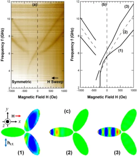
FIG. 2. (a) The FMR spectra obtained for a symmetric, three-fold permalloy cluster. The frequency f was swept between 2 GHz and 12 GHz at fixed magnetic fields -1000 Oe ≤ H ≤ +1000 Oe. The black arrow indicates the direction of the magnetic field sweep. (b) A theoretical simulation of the FMR f vs. H spectrum. (c) The corresponding out-of-plane component of the magnetization for: (1) the first fundamental mode, (2) a backward-like volume mode, and (3) the second (though highly hybridized) fundamental mode.
056020-4 Bang et al. AIP Advances 8, 056020 (2018)
with minor and major axes of 200 and 500 nm, respectively, for an aspect ratio of 2/5. This choice was motivated by the fact that overly elongated ellipses are known to have low-frequency excitations localized in narrow areas at the ends of the segment (longitudinally),15,16and those modes are unlikely
to give large FMR signals. Similar calculations were performed for asymmetric samples having an aspect ratio 1/5.
The FMR absorption spectra from the threefold-symmetric sample are shown in a false-color-coded image in Fig.2(a), while the dynamical matrix results are shown in Fig.2(b). Modes (1) and (3) in Fig. 2(b), were clearly detected. The first lies at lower frequency and has a larger intensity, while the second is at higher frequency. Note the overall agreement is rather good, particularly for the behavior of the fundamental mode (1) of Fig.2, which exhibits a softening effect at negative fields. The softening effect is a non-linear behavior of the frequency vs. field curve when approaching the reversal field. The distributions of the dynamic magnetization associated with these modes are shown in Fig.2(c). Mode (1) is localized within the two oblique macrospins with larger amplitude at lower frequencies; modes (2) and (3) are localized in the horizontal macrospin with lower amplitude at
FIG. 3. (a) The FMR spectra obtained for a permalloy cluster consisting of asymmetric segments. Here, the frequency was swept between 2 GHz and 12 GHz at fixed magnetic fields ranging between +1000 Oe and –1000 Oe. The black arrow indicates the direction of the magnetic field sweep. The line is a guide for a faint spectrum. (b) A theoretical simulation of the FMR f vs. H spectrum. (c) The corresponding out-of-plane component of the magnetization for: (1) the first fundamental mode, and (2) the second fundamental mode.
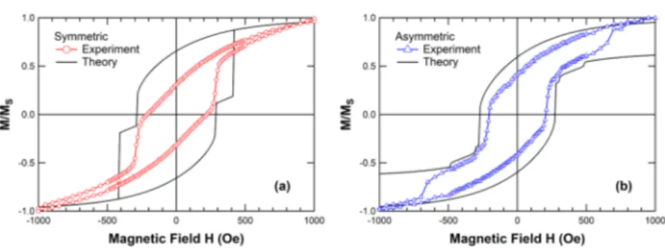
FIG. 4. Experimental and theoretical M-H curves; (a) symmetric and (b) asymmetric sample.
higher frequencies. The predicted mode (2) is a backward-like volume mode with two nodal lines orthogonal to the local magnetization direction; however, it was not detected.
Figure3(a)shows the experimental field dependence of the observed spectra for the asymmetric sample, while 3(b) shows the corresponding theoretically calculated spectra. Here, we observe only a single dominant mode. Figure3(c)shows the predicted mode profiles for the two principal modes. Mode (1) of the asymmetric sample in Fig.3(a)is a similar to mode (1) of the symmetric sample of Fig. 2(a). There is evidence of a weaker mode on the positive field side at higher frequency in Fig.3(a), which corresponds to mode (2) in Fig3(b). As with the symmetric sample, we find that the experimental data for the asymmetric sample are in good agreement with the theoretical predictions.
In order to simulate the equilibrium magnetization configuration, OOMMF17using 5 × 5 × 15 nm3 micromagnetic cells was used with following parameters: magnetic moment 1.0 × 10⁸µB and 0.6 × 10⁸ µ
Bfor only thinner cluster in the asymmetric sample, saturation magnetization Ms = 860
kA/m, and exchange stiffness parameter A = 1.3 × 10⁻¹¹J/m. The normalized hysteresis loops, M
vs. H, for the symmetric and asymmetric samples are shown in Fig.4(a)and(b), respectively. Since our artificial macrospins are elongated nanodots, magnetization reversal occurs gradually by partial rotation of the magnetic moments within each macrospin. For the symmetric sample in Fig.4(a), the simulated magnetization in the segments gradually decreases with decreasing magnetic field down to a first critical field at 290 Oe, which is in reasonable agreement with a feature in the experimental data; however, the simulations also show a second critical field at 420 Oe which the experiments to not show. Note that the minimum of the effective field in the simulations occurs at the inner end of the horizontal macrospin, which is not clearly detected in the FMR spectra in Fig2(a). Below the second critical field, the macrospins are completely aligned with the applied field (opposite to their original direction).
Due to the broken symmetry of the asymmetric sample in Fig.4(b), the simulations predict three critical fields which occur at 280, 310, and 490 Oe. Experimentally (blue open triangles), two of the critical fields occur close to predicted values, while a third one differs by approximately ∼200 Oe. The reversal in the asymmetric sample is relatively more extended due to the stronger shape anisotropy and higher exchange stiffness value. Further details concerning the theoretical predictions will be reported elsewhere.18
IV. CONCLUSION
We have performed measurements, calculations and simulations of the static and dynamic response of a system consisting of three closely-positioned elliptical macro spins. Such studies are clearly essential if one is to understand the dynamics of spin-ice and other lattices involving similar building blocks.
ACKNOWLEDGMENTS
Work at Northwestern was supported by the NSF under grant DMR 1507058. Work at the University of Kentucky was supported by the NSF under grant DMR 1506979. Work at Argonne was
056020-6 Bang et al. AIP Advances 8, 056020 (2018)
supported by the U.S. Department of Energy, Office of Science, Materials Science and Engineering Division. Use was made of the Center for Nanoscale Materials, an Office of Science user facility, which is supported by DOE, Office of Science, Basic Energy Science under Contract No. DE-AC02-06CH11357.
1E. Mengotti, L. J. Heyderman, A. F. Rodriguez, F. Nolting, R. V. Hugli, and H. B. Braun,Nat. Phys.7(1), 68–74 (2011). 2C. Nisoli, R. Moessner, and P. Schiffer,Rev. Mod. Phys.85(4), 1473–1490 (2013).
3Y. Qi, T. Brintlinger, and J. Cumings,Phys. Rev. B77, 094418 (2008).
4R. F. Wang, C. Nisoli, R. S. Freitas, J. Li, W. McConville, B. J. Cooley, M. S. Lund, N. Samarth, C. Leighton, V. H. Crespi, and P. Schiffer,Nature439(7074), 303–306 (2006).
5F. Montoncello, L. Giovannini, B. Farmer, and L. De Long,J. Magn. Magn. Mater.423, 158–163 (2017).
6F. G. Aliev, J. F. Sierra, A. A. Awad, G. N. Kakazei, D. S. Han, S. K. Kim, V. Metlushko, B. Ilic, and K. Y. Guslienko,Phys. Rev. B79, 174433 (2009).
7B. K. Kuanr, R. Lopusnik, L. M. Malkinski, M. Wenger, M. H. Yu, D. Scherer, R. E. Camley, and Z. Celinski,J. Appl. Phys.103, 07C508 (2008).
8J. Podbielski, D. Heitmann, and D. Grundler,Phys. Rev. Lett.99, 207202 (2007).
9R. Zivieri, P. Malago, L. Giovannini, S. Tacchi, G. Gubbiotti, and A. O. Adeyeye,J. Phys. Condens. Matter25, 336002 (2013).
10R. Adam, Y. Khivintsev, R. Hertel, C. M. Schneider, A. Hutchison, R. Camley, and Z. Celinski,J. Appl. Phys.101, 09F516 (2007).
11K. Y. Guslienko, G. N. Kakazei, Y. V. Kobljanskyj, G. A. Melkov, V. Novosad, and A. N. Slavin,New J. Phys.16, 063044 (2014).
12J. F. Sierra, A. A. Awad, G. N. Kakazei, F. J. Palomares, and F. G. Alievi,IEEE Trans. Magn.44(11), 3063–3066 (2008). 13M. B. Jungfleisch, W. Zhang, J. J. Ding, W. J. Jiang, J. Sklenar, J. E. Pearson, J. B. Ketterson, and A. Hoffmann,Appl.
Phys. Lett.108, 052403 (2016).
14L. Giovannini, F. Montoncello, and F. Nizzoli,Phys. Rev.B75, 024416 (2007).
15G. Gubbiotti, G. Carlotti, T. Okuno, M. Grimsditch, L. Giovannini, F. Montoncello, and F. Nizzoli,Phys. Rev. B72, 184419 (2005).
16J. Jorzick, S. O. Demokritov, B. Hillebrands, M. Bailleul, C. Fermon, K. Y. Guslienko, A. N. Slavin, D. V. Berkov, and N. L. Gorn,Phys. Rev. Lett.88, 047204 (2002).
17M. Donahue and D. G. Porter, Interagency Report NISTIR 6376 (1999).
18F. Montoncello, L. Giovannini, W. Bang, J. B. Ketterson, M. B. Jungfleisch, A. Hoffmann, B. W. Farmer, and L. E. De Long, (unpublished).