Alma Mater Studiorum
University of Bologna
FACULTY OF ENGINEERING
DICAM
Department of Civil, Chemical, Environmental and Material Engineering
Civil Engineering
Roads, Railroads and Airports Constructions LM
Flexible pavement design using
Mechanistic-Empirical methods:
the Californian approach
Master of Science
thesis of:
Alessio Montuschi
Supervisor:
Professor Giulio Dondi
Advisors:
Assistant Researcher Matteo Pettinari
Session III
Academic year 2011/2012
Alma Mater Studiorum
Università degli Studi di Bologna
FACOLTÀ DI INGEGNERIA
DICAM
Dipartimento di Ingegneria Civile, Chimica, Ambientale e dei Materiali
Ingegneria Civile
Costruzione di Strade Ferrovie ed Aeroporti LM
Flexible pavement design using
Mechanistic-Empirical methods:
the Californian approach
Tesi di laurea di:
Alessio Montuschi
Relatore:
Chiar.mo Prof. Ing. Giulio Dondi
Correlatore:
Dott. Ing. Matteo Pettinari
Sessione III
Anno Accademico 2011/2012
vii
Key Words
Maintenance
Mechanistic-Empirical design
CalME
pavement performance
overlay
ix
Abstract
(English version)
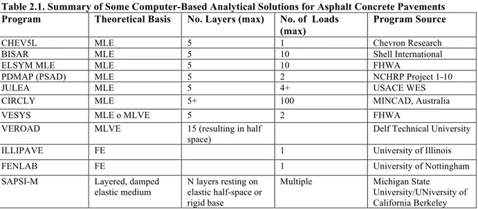
Pavement structural design is a complex task. Although the basic geometry of a road system is quite simple, everything else is not. Traffic loading is a heterogeneous mix of vehicles, axle types, and axle loads with distributions that vary with time through the day, from season to season, and over pavement design life. Since the beginning of 1900 empirical methods for design have been used, as in most of those of the American Association of State Highway and Transportation Officials (AASHTO) guides, but several developments in recent decades have offered the opportunity for more rational and rigorous pavement design procedures. A better characterization of materials and the development of constitutive models now allow a greater ability to predict the pavement response to load and climate effects, and the possibility of using dedicated softwares that use fatigue laws relating to the current materials behavior. Volumetric (Mix Design) and mechanical (Permanent deformation and Fatigue performance) characterization properties are fundamental and necessary for a realistic estimate of pavement performance.
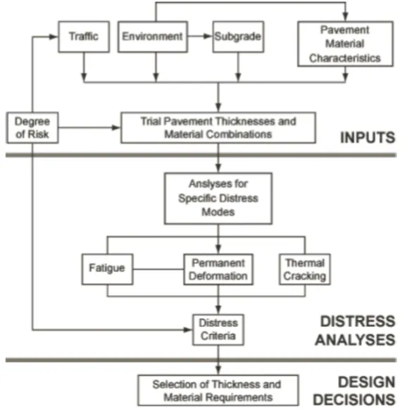
To date, the pavement design is still based on empirical methodologies and specifications in which, starting from selected input data, the final results and the thickness layers are directly established without considering the numerous variables involved during the service life of the pavement structure. For this reason new and more realistic mechanistic methods are increasingly adopted and analyzed. The main objective of this thesis is precisely to evaluate the potential application and validation of a mechanistic-empirical approach, analyzing the outcomes of pavement simulations in which several maintenance interventions are applied. The Empirical-Mechanistic method consists of a structural model able to predict the stress and strain states within the pavement structure under the different traffic and environmental conditions, and of empirical models, that calibrated with the behavior of the materials, connect the structural response to the pavement performances.
The year 1996 marks the beginning of an extensive research project for the California aimed at the development of Empirical-Mechanistic methods for pavement design. Thanks to advances in the pavement field it has reached the first version of the software CalME, which was used for the development of this dissertation. Of the three approaches, of which the is composed (Empirical, Empirical-Mechanistic classic and Empirical-Mechanistic Incremental-Recursive), the procedure Incremental-Recursive was the application of choice. It is based on several models, which
attempt to represent the numerous variables that affect the behavior of a pavement structure. Among them, this paper is focused on fatigue damage models and accumulation of permanent deformation models achieved through a careful material characterization in the laboratory. One of the innovations introduced by CalME with this approach is the ability to evaluate the interaction between the various layers in order to identify the ideal thicknesses in both the design and maintenance interventions.
In Chapter 1 the importance of maintenance in pavement and road fields is analyzed. The different types of pavements with relating distresses are described and the main maintenance operations are proposed. A short historical excursus on the pavement design evolution from the early empirical methods to the more complex mechanistic methods is shown, through the useful mechanistic-empirical methods, in Chapter 2. The CalME (Mechanistic Empirical Design Software) is introduced in Chapter 3. In particular, the Incremental-Recursive procedure is analyzed and the models on which it is based. The experimental research starts in Chapter 4, in which an empirical method is utilized for the design of two pavements, using the Caltrans Highway Design Manual. Finally in Chapter 5 the results of the asphalt structures simulations are shown. Consequently the results of other structure simulations subject to several maintenance interventions are presented. For each situation considered the total surface cracking, the total rutting and fatigue damage and rut depth on each layer were analyzed
The research was carried out in particular to the Pavement Research Center at the University of California, Berkeley (UCPRC), with the support of the DICAM from the University of Bologna.
xi
Abstract
(Italian version)
La progettazione strutturale della pavimentazione stradale è un compito complesso. Sebbene la geometria di un sistema stradale presenti meno problematiche, il dimensionamento di una struttura stradale è influenzato da numerose variabili: il carico dovuto al traffico è una miscela eterogenea di veicoli, i tipi di assi e i carichi agenti su di essi hanno distribuzioni che variano nel tempo, le condizioni climatiche non sono costanti durante l’anno e nemmeno nell’arco di una giornata. Dagli inizi del ‘900 si è fatto ricorso a metodi empirici per la progettazione, come in gran parte quelli dell’American Association of State Highway and Transportation Officials (AASHTO), ma diversi sviluppi negli ultimi decenni hanno offerto l’occasione per più razionali e rigorose procedure di progettazione. Una migliore caratterizzazione dei materiali e lo sviluppo di modelli costitutivi permettono ora una migliore capacità di prevedere le risposte delle pavimentazioni agli effetti di carico e clima, e la possibilità di usare softwares dedicati che utilizzano leggi di fatica relative al reale comportamento dei materiali. La caratterizzazione volumetrica e meccanica di un conglomerato bituminoso è quindi fondamentale e necessaria per una realistica previsione delle performance di una pavimentazione stradale.
Ad oggi la progettazione stradale è ancora basata su metodologie empiriche e capitolati in cui, partendo da alcuni dati in input, i risultati finali e gli spessori degli strati sono dati direttamente senza tenere conto delle numerose variabili che intervengono durante la vita utile della struttura. Per questo motivo si sta cercando di spingersi verso nuove e più realistiche metodologie meccanicistiche. Obiettivo principale di questa tesi è appunto valutare le potenzialità di applicazione di un nuovo approccio Empirico-Meccanicistico nell’ambito della progettazione delle sovrastrutture stradali, analizzando i risultati derivanti da simulazioni ottenute attraverso il CalME, software in fase di sviluppo presso l’Università di Berkeley. La progettazione Empirico-Meccanicistica consiste di un modello strutturale capace di prevedere gli stati tenso-deformativi all’interno della pavimentazione sotto l’azione del traffico e in funzione delle condizioni climatiche e di modelli empirici, calibrati sul comportamento dei materiali, che collegano la risposta strutturale alle performance della pavimentazione.
Il 1996 segna l’inizio per la California di un estensivo progetto di ricerca mirato allo sviluppo dei metodi di progetto Empirico-Meccanicistici per le pavimentazioni stradali. Grazie ai continui progressi in campo stradale si è arrivati alla prima versione del software CalME, la cui ultima versione è stata utilizzata per questo elaborato. Dei tre approcci dei quali il programma si
xii
compone (Empirico, Empirico-Meccanicistico classico ed Empirico-Meccanicistico Incrementale-Ricorsivo) si è utilizzata la procedura Incrementale-Ricorsiva. Essa è basata su numerosi modelli che cercano di rappresentare le variabili che condizionano il comportamento di una pavimentazione stradale. Tra tutti, in questo elaborato, ci si è soffermati sui modelli di danno da fatica e sui modelli di accumulo di deformazioni permanenti conseguiti tramite un’accurata caratterizzazione dei materiali in laboratorio. Una delle innovazioni introdotte dal CalME con tale approccio è la possibilità di valutare l’interazione tra i vari strati al fine di individuare gli spessori ideali sia in fase di progettazione che in fase di manutenzione.
Nel capitolo 1 è analizzata l’importanza della manutenzione in ambito stradale. Sono descritte le diverse tipologie di pavimentazione, i relativi ammaloramenti cui sono soggette ed introdotti i principali interventi manutentivi volti al risanamento delle stesse.
Nel capitolo 2 è esposto un breve excursus storico sull’evoluzione della progettazione stradale dai primi metodi empirici fino ai più complessi metodi meccanicistici, passando per i metodi empirico-meccanicistici ed i relativi modelli di performance utilizzati.
Nel capitolo 3 è stato descritto il CalME, Mechanistic Empirical Design Software. In particolare è stata analizzata la procedura Incrementale-Ricorsiva e i modelli che ne sono alla base.
Nel capitolo 4 è stato introdotto il programma sperimentale attraverso la definizione di due sovrastrutture stradali e dei materiali costituenti. Il dimensionamento delle stesse è stato ottimizzato secondo il manuale di progettazione attualmente in uso presso l’ente gestore delle infrastrutture stradali dello stato della California.
Infine nel capitolo 5 sono riportati i risultati delle simulazioni effettuate con le pavimentazioni in esame. Sono stati analizzate la superficie totale fessurata, l’ormaiamento totale e il danno a fatica e ormaiamento relativo a ogni strato.
La ricerca è stata eseguita presso il Pavement Research Center dell’Università di Berkeley sotto la supervisione del Prof. Carl L. Monismith, con il supporto del DICAM dell’Università di Bologna.
xiii
Contents
Key Words………...........vii
Abstract (English version)......ix
Abstract (Italian version)...xi
Contents……….……..xiii
Chapter 1: Pavement Preservation……….……... 1
1.1 Introduction...3 1.2 Pavement Preservation….. ....…………... 3 1.2.1 Routine maintenance...4 1.2.2 Periodic maintenance...4 1.2.3 Urgent maintenance………...4 1.3 Pavement Types….……... ………..………...5 1.3.1 Introduction…...5 1.3.2 Flexible Pavement………...…...6
1.3.2.1 Basic Structural Elements...7
1.3.2.1.1 Surface Course...7
1.3.2.1.2 Base Course...8
1.3.2.1.2 Subbase Course ...8
1.3.2.2 Flexible pavement types...9
1.3.3 Rigid Pavement…….…...…...10
1.3.3.1 Basic Structural Elements...10
1.3.3.1.1 Surface Course...11
1.3.3.1.2 Base Course...11
1.3.3.1.2 Subbase Course ...12
xiv
1.3.3.2.1 Contraction Joints...13
1.3.3.2.2 Expansion Joints...14
1.3.3.2.3 Isolation Joints...15
1.3.3.2.4 Construction Joints...15
1.3.3.3 Rigid pavement types...16
1.4 Pavement distresses...………..……….……….17
1.4.1 Introduction……...17
1.4.2 Flexible Pavement Distresses...17
1.4.2.1 Fatigue (Alligator) Cracking………...17
1.4.2.2 Block Cracking and Transverse (Thermal)...18
1.4.2.3 Potholes...………...19
1.4.2.4 Bleeding...………...20
1.4.2.5 Rutting...………...21
1.4.2.6 Corrugation and Shoving...………...22
1.4.2.7 Ravelling and Weathering....………...22
1.4.2.8 Pumping...………...23
1.4.2.9 Longitudinal Cracking...………...23
1.4.2.10 Surface Deterioration...………...24
1.5 Maintenance and Rehabilitation...………..……….……….24
1.5.1 Introduction…...24
1.5.2 Maintenance for flexible pavement...25
1.5.2.1 Crack seals...25
1.5.2.2 Fog seals...25
1.5.2.3 Slurry seals...26
1.5.2.4 Bituminous Surface Treatments (BST)...26
1.5.2.5 Patches...27
1.5.2.6 Thin Maintenance Overlays...27
1.5.2.6.1 Dense Graded Thin Overlays...28
1.5.2.6.2 Open Graded Mixes...28
1.5.2.6.3 Gap Graded Mixtures...29
xv
1.5.3.1 Structural HMA Overlays...29
1.5.3.1.1 Engineering Judgement...30
1.5.3.1.2 Component Analysis...30
1.5.3.1.3 Non Destructive Testing with Limiting Deflection Criteria...30
1.5.3.1.4 Mechanistic-Empirical Analysis...30
1.5.3.2 Structural PCC Overlays...31
1.5.3.2.1 Unbounded-Classical Whitetopping...31
1.5.3.2.2 Bpunded-Thin composite Whitetopping...32
Chapter 2: Evolution of Pavement Design Procedure...……...33
2.1 Introduction ...35
2.2 Review of Flexible Pavement Design Principles...35
2.2.1 Empirical Methods...……..……...36
2.2.2 Mechanistic-Empirical Methods...……..……...37
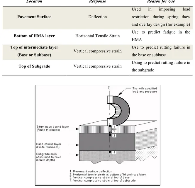
2.2.2.1 Basic Inputs and Outcomes...………...38
2.3 Pavement Design Procedure...42
2.3.1 The 1993 AASHTO Guide...….………...43
2.3.1.1 AASHO Road Test and Early Versions of the Guide.…...43
2.3.1.2 Current Design Equation..…...….………….………..…...47
2.3.1.3 Input Variables...……..……….………...……….49 2.3.1.4 Reliability...…..….……..………53 2.3.1.5 Addition Considerations...…..….……..………54 2.3.2 M-E PDG………..………..…….………..………...56 2.3.2.1 Design Process.……….….………..…...57 2.3.2.2 Design Input………....…….….………..…...59
2.3.2.3 Pavement Response Models……....…….….………..…...65
2.3.2.4 Empirical Performance Models……....…....….………..…...69
xvi
Chapter 3: CalME: California Mechanistic – Empirical design software……...79
3.1 Introduction to CalME and CalBack...81
3.1.1 Overview……...81
3.1.2 CalME………...81
3.1.3 CalBack………...83
3.2 CalME Design Methods: The “Caltrans” Empirical Design Methods...86
3.2.1 R-Value Method for New Pavements ……..……...86
3.2.2 Deflection Reduction Method for Rehabilitation...86
3.3 CalME Design Methods: The “Classical” Mechanistic-Empirical Design Method...89
3.3.1 Introduction...89
3.3.2 Pavement Response…..………….………...90
3.3.2.1 Introduction…….……….………..…...90
3.3.2.2 Boussinesque’s equations…...….………….………..…...92
3.3.2.3 Burmister’s Elastic Models....……..……….………...……….94
3.3.2.4 Odemark’s Method of the Equivalent Thickness.…..….……..………95
3.3.3 Pavement Performance………..…….………..………...97
3.3.3.1 Design Criteria……….….………..…...97
3.3.3.2 Default Design Criteria in CalME..…….….………..…...100
3.4 CalME Design Methods: The “Incremental-Recursive” procedure………...………...102
3.4.1 Introduction...102
3.4.2 CalME Models used in the I-R procedure..…………..………...104
3.4.2.1 Asphalt Concrete Master Curve..………….………..…...104
3.4.2.2 Aging of Asphalt Binder and Hardening of Asphalt Mixes...110
3.4.2.3 Effect of seasonal variations on unbound materials....…….……...…….111
3.4.2.4 Effect of confinement and load level variations on unbound materials...112
3.4.2.5 Damage functions and the Time-Hardening procedure…...…………....113
3.4.2.6 AC Fatigue Damage model … .… ……… ………. .………...116
3.4.2.7 AC Fatigue cracking evaluation………..…….……...……118
3.4.2.8 Reflection cracking in an overlay asphalt layer………..…119
xvii
3.4.2.10 AC Permanent shear strain accumulation………..………121
3.4.2.11 AC Rutting evaluation….………..………122
3.4.2.12 Unbound materials Rutting evaluation…..…...……..………122
3.4.2.13Crushing damage…..…...……….…...…...……....………....123
Chapter 4: Experimental Program Description …...125
4.1 Introduction...127
4.2 Pavement Structure Layers...127
4.3 Traffic Consideration...………...129
4.3.1 Traffic Index Calculation...129
4.4 Soil Characteristics...………...131
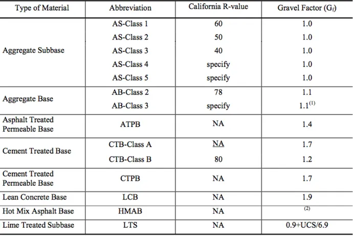
4.4.1 California R-Value..………...131
4.5 Engineering Procedures for New Projects.………...132
4.5.1 Empirical Method..………...132
4.6 Pavement design through Caltrans Highway Design Manual...136
Chapter 5: Pavement Design...139
5.1 Pavement structure definition, Traffic and Climate…...141
5.2 Performance Simulation Results... ...143
5.2.1 Central Coast conditions…...143
5.2.2 Desert conditions...…...147
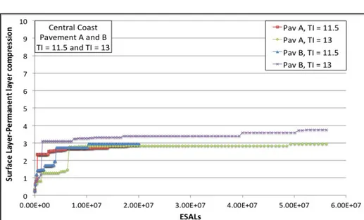
5.3 Performance Simulation Results, overlay applications...152
5.3.1 Central Coast conditions…...152
xviii
5.3.1.2 Pavement structure A and TI=13...156
5.3.1.3 Pavement structure B and TI=11.5……....……..…...159
5.3.1.4 Pavement structure B and TI=13...…...162
5.3.2 Desert conditions...…...165
5.3.1.1 Pavement structure A and TI=11.5...165
5.3.1.2 Pavement structure A and TI=13...168
5.3.1.3 Pavement structure B and TI=11.5……....……..…...171
5.3.1.4 Pavement structure B and TI=13...…...174
5.4 Result Analysis..………... 177
Conclusions...... 179
Chapter I
Pavement
Preservation
Chapter I – Pavement Preservation
3
1.1 Introduction
Roads are among the most important public assets in many countries. Developed countries require a core transportation network that carries approximately 80 percent of national traffic, including key roads in urban areas and roads providing sufficient access to rural areas. A portion of the overall transportation budget thus has to be spent on construction and the remainder on maintaining the core network. Many countries have tended to favor new construction, rehabilitation, or reconstruction of roads over maintenance. This has led to a steady increase in the backlog of road repairs and a loss of development impact. Road improvements bring immediate and at times dramatic benefits to road users such as improved access to hospitals, schools, and markets. Smooth roads also improve comfort, speed, safety and lower vehicle operating costs. For these benefits to be sustained, road improvements must be followed by a well planned maintenance program.
Postponing road maintenance results in high direct and indirect costs. If road defects are repaired promptly, the cost is usually modest. If defects are neglected, an entire road section may fail completely, requiring full reconstruction on average at three or more times the cost of quick repairs. Delayed maintenance has indirect costs as well. Neglected roads steadily become more difficult to use, resulting in increased vehicle operating costs (more frequent repairs, more fuel use) and a reluctance by transport operators to use the roads. This imposes a heavy burden on the economy. As passenger and freight services are curtailed, there is a consequent loss of economic and social development opportunities.
1.2 Pavement Preservation
The combined effects of traffic loading and environment will cause every pavement, no matter how well-designed/constructed to deteriorate over time. Maintenance and rehabilitation are the solutions to preserve the pavement from this deterioration process. Maintenance actions help slow the rate of deterioration by identifying and addressing specific pavement deficiencies that contribute to overall deterioration. Rehabilitation is the act of repairing portions of an existing pavement to reset the deterioration process. Reconstructing an entire pavement, however, is not considered rehabilitation but rather new construction because the methods used are generally those developed for new pavement construction. Although maintenance can slow the rate of pavement deterioration, it cannot stop it. Therefore eventually the effects of deterioration need to
Chapter I – Pavement Preservation
be reversed by adding or replacing material in the existing pavement structure and this is called rehabilitation (www.pavementinteractive.org).
The goal of maintenance is to preserve the asset, and not to upgrade it. Unlike major road works maintenance must be done regularly. Pavement maintenance comprises “activities to keep pavement, shoulders, slopes, drainage facilities and all other structures and property within the road margins as near as possible to their as-constructed or renewed condition” (PIARC 1994). It includes minor repairs and improvements to eliminate the cause of defects and to avoid excessive repetition of maintenance efforts. For management and operational convenience, road maintenance is categorized as routine, periodic, and urgent.
1.2.1 Routine maintenance
Routine maintenance, which comprises small-scale works conducted regularly, aims “to ensure the daily passability and safety of existing roads in the short-run and to prevent premature deterioration of the roads” (PIARC 1994). Typical activities include roadside verge clearing and grass cutting, cleaning of silted ditches and culverts, patching, and pothole repair. For gravel roads it may include regrading every six months. Activitie frequency varies, and conseqently requires attention once or more per week or month.
1.2.2 Periodic maintenance
Periodic maintenance, which covers activities on a section of road at regular and relatively long intervals, aims “to preserve the structural integrity of the road” (WB Maintenance website). These operations tend to be in large scale, requiring specialized equipment and personnel. They cost more than routine maintenance works and require specific identification and planning for implementation and often even design. Activities can be classified as preventive, resurfacing, overlay, and pavement reconstruction. Resealing and overlay works are generally undertaken in response to measured deterioration in road conditions. For a paved road, repaving is needed usually every eight years; for a gravel road, re-graveling is needed usually every three years.
1.2.3 Urgent maintenance
Urgent maintenance is undertaken for repairs that cannot be foreseen but require immediate attention, such as collapsed culverts or landslides that block a road.
Maintenance does not include rehabilitation, building shoulders, or widening roads. If the sections to be rebuilt constitute more than 25 percent of the road’s length, the work is classified as rehabilitation and not maintenance.
Chapter I – Pavement Preservation
5
1.3 PAVEMENT TYPES
1.3.1 Introduction
Generally, all surfaced pavement types can be categorized into two groups, flexible and rigid. Flexible pavements are those which are surfaced with bituminous (or asphalt) materials. These can be either in the form of HMA surface courses (generally used on higher volume roads such as the Interstate highway network) or pavement surface treatments (such as a bituminous surface treatment (BST) generally found on lower volume roads). These types of pavements are called "flexible" since the total pavement structure "deflects" or "bends" due to traffic loads. A flexible pavement structure is generally composed of several layers of materials which can allow this "flexing". On the other hand, rigid pavements are composed of a PCC surface course. Such pavements are substantially "stiffer" than flexible pavements due to the high modulus of elasticity of the PCC material. Furthermore these pavements can have reinforcing steel, which is generally used to reduce or eliminate joints. Each of these pavement types distribute loads over the subgrade in a different manner. Flexible pavement uses more flexible surface course and distributes loads over a smaller area. It relies on a combination of layers for transmitting load to the subgrade (see Figure 1). Rigid pavement, because of PCC's high elastic modulus (stiffness), tends to distribute the load over a relatively wide area of subgrade (see Figure 1.1). The concrete slab itself supplies most of a rigid pavement's structural capacity.
Chapter I – Pavement Preservation
Overall, it may be somewhat confusing as to why one pavement is used versus another. In general, state highway agencies generally select pavement type either by policy, economics, or both. Flexible pavements usually require some sort of maintenance or rehabilitation every 10 to 15 years. Rigid pavements, on the other hand, can often serve 20 to 40 years with little or no maintenance or rehabilitation. Thus, it should come as no surprise that rigid pavements are often used in urban, high traffic areas, but, naturally, there are trade-offs. For example, when a flexible pavement requires maintenance and rehabilitation, the options are generally less expensive and quicker to perform than for rigid pavements. This next subdivision to those found in Washington State Department of Transportation (WSDOT).
1.3.2 Flexible Pavement
The term flexible pavement is derived by the fact that the total pavement structure deflects, or flexes, under loading. A flexible pavement structure is typically composed of several layers of material. Each layer receives the loads from the above layer, spreads this load, then passes on these loads to the next layer below. Thus, the further down in the pavement structure a particular layer is, the less load (in terms of force per area) it will carry.
In order to take maximum advantage of this property, material layers are usually arranged in order of descending load bearing capacity with the highest load bearing capacity material (and most expensive) on the top and the lowest load bearing capacity material (and least expensive) on the bottom. This section describes the typical flexible pavement structure consisting of:
• Surface course. This is the top layer and the layer that comes in contact with
traffic. It may be composed of one or several different HMA sublayers.
• Base course. This is the layer directly below the HMA layer and generally consists
of aggregate (either stabilized or unstabilized).
• Subbase course. This is the layer (or layers) under the base layer. A subbase is not
Chapter I – Pavement Preservation
7
1.3.2.1 Basic Structural Elements
A typical flexible pavement structure (see Figure 1.2) consists of the surface course underlying base and subbase courses. Each of these layers contributes to structural support and drainage. The surface course (typically an HMA layer) is the stiffest (measured by resilient modulus) and contributes the most to pavement strength. The underlying layers are less stiff but are still important to pavement strength as well as drainage and frost protection. A typical structural design results in a series of layers that gradually decrease in material quality with depth.
Figure 1.2. Flexible Pavement Structure.
1.3.2.1.1 Surface Course
The surface course is the layer in contact with the traffic loads and normally contains the highest quality materials. It has characteristics such as friction, smoothness, noise control, rutting, shoving resistance, and drainage. In addition, it prevents excessive quantities of surface water entering into the underlying base, subbase, and subgrade. The top structural layer of material is sometimes subdivided into two layers :
1. Wearing Course. This is the layer in direct contact with the traffic loads. It is used to take the brunt of traffic wear and can be removed and replaced as it becomes worn. A properly designed (and funded) preservation program should be able to identify pavement surface distress while it is still confined to the wearing course. Consequently, the wearing course can be rehabilitated before distress propagates into the underlying intermediate/binder course.
2. Intermediate/Binder Course. This layer provides the bulk of the HMA structure. It's purpose is to distribute load.
Chapter I – Pavement Preservation
1.3.2.1.2 Base Course
The base course is immediately beneath the surface course. It provides additional load distribution and contributes to drainage and frost resistance. Base courses are usually constructed out of:
1. Aggregate. Base courses are most typically constructed from durable aggregates (see Figure 1.3) that will not be damaged by moisture or frost action. Aggregates can be either stabilized or unstabilized.
2. HMA. In certain situations where high base stiffness is desired, base courses can be constructed using a variety of HMA mixes. In relation to surface course HMA mixes, base course mixes usually contain larger maximum aggregate sizes, are more open graded and are subject to more lenient specifications.
Figure 1.3. Limerock Base Course Undergoing Final Grading.
1.3.2.1.3 Subbase Course
The subbase course, positioned between the base course and the subgrade, functions primarily as structural support and it can also:
Chapter I – Pavement Preservation
9 2. Improve drainage.
3. Minimize frost action damage.
4. Provide a working platform for construction.
A subbase course is not always needed or used. It consists of lower quality materials than the base course but possesses higher quality material when compared to the subgrade soils. For example, a pavement constructed over a high quality, stiff subgrade may not need the additional features offered by a subbase course and can consequently be omitted from design. However, a pavement constructed over a low quality soil such as a swelling clay may require the additional load distribution characteristic that a subbase course can offer. In this scenario the subbase course may consist of high quality filler used to replace poor quality subgrade.
1.3.2.2 Flexible pavement types
There are many different types of flexible pavements. Three of the more common types of HMA mix types used in the U.S.:
• Dense-graded HMA. Dense-graded HMA is a versatile, all-around mix making it the
most common and well-understood mix type in the U.S.
• Stone matrix asphalt (SMA). SMA, although relatively new in the U.S., has been used
in Europe as a surface course for years to support heavy traffic loads and resist studded tire wear.
• Open-graded HMA. This includes both open-graded friction course (OGFC) and
asphalt treated permeable materials (ATPM). Open-graded mixes are typically used as wearing courses (OGFC) or underlying drainage layers (ATPM) because of the special advantages offered by their porosity.
Chapter I – Pavement Preservation
1.3.3 Rigid Pavement
Rigid pavements are so named because the pavement structure deflects very little under loading due to the high modulus of elasticity of their surface course. A rigid pavement structure is typically composed of a PCC surface course built on top of either (1) the subgrade or (2) an underlying base course. Because of its relative rigidity, the pavement structure distributes loads over a wide area with only one, or at most two, structural layers. This section describes the typical rigid pavement structure consisting of:
• Surface course. This is the top layer, which consists of the PCC slab.
• Base course. This is the layer directly below the PCC layer and generally consists of
aggregate or stabilized subgrade.
• Subbase course. This is the layer (or layers) under the base layer. A subbase is not
always needed and therefore may often be omitted.
1.3.3.1 Basic Structural Elements
A typical rigid pavement structure (see Figure 1.4) consists of the surface course and the underlying base and subbase courses (if used).
Figure 1.4. Basic Rigid Pavement Structure.
The surface course (made of PCC) is the stiffest (as measured by resilient modulus) and provides the majority of strength. The underlying layers are orders of magnitude less stiff but still make important contributions to pavement strength as well as drainage and frost protection.
Chapter I – Pavement Preservation
11
!"#"#"!"!$%&'()*+$,-&'.+$
The surface course is the layer in contact with traffic loads and is made of PCC. It provides characteristics such as friction (see Figure 1.5), smoothness, noise control and drainage. In addition, it serves as a waterproofing layer to the underlying base, subbase and subgrade. The surface course can vary in thickness but is usually between 150 mm (for light loading) and 300 mm (12 inches) (for heavy loads and high traffic). Figure 1.6 shows a 300 mm surface course (Hall, Correa, & Carpenter, 2001).
Figure 1.5. PCC Surface. Figure1.6. Rigid Pavement Slab
(Surface Course) Thickness.
!"#"#"!"/$0).+$,-&'.+$
The base course is immediately beneath the surface course. It provides (1) additional load distribution, (2) contributes to drainage and frost resistance, (3) uniform support to the pavement and (4) a stable platform for construction equipment (ACPA, 2001). Bases also help prevent subgrade soil movement due to slab pumping and are usually constructed out of:
1. Aggregate base. A simple base course of crushed aggregate has been a common option since the early 1900s and is still appropriate in many situations today.
2. Stabilized aggregate or soil (see Figure 1.7). Stabilizing agents are used to bind otherwise loose particles to one another, providing strength and cohesion. Cement
Chapter I – Pavement Preservation
treated bases (CTBs) can be built to as much as 20 - 25 percent of the surface course strength (FHWA, 1999). However, cement treated bases (CTBs) used in the 1950s and early 1960s had a tendency to lose excessive amounts of material leading to panel cracking and settling.
3. Dense-graded HMA. In situations where high base stiffness is desired base courses can be constructed using a dense-graded HMA layer.
4. Permeable HMA. In certain situations where high base stiffness and excellent drainage is desired, base courses can be constructed using an open graded HMA. Recent research may indicate some significant problems with ATPB use. 5. Lean concrete. Contains less portland cement paste than a typical PCC and is stronger
than a stabilized aggregate. Lean concrete bases (LCBs) can be built to as much as 25 - 50 percent of the surface course strength (FHWA, 1999). A lean concrete base functions much like a regular PCC surface course and therefore, it requires construction joints and will crack over time. These joints and cracks can potentially cause reflection cracking in the surface course if they are not carefully matched.
Figura 1.7. Completed CTB with Curing Seal.
!"#"#"!"#$%&11).+$,-&'.+$
The subbase course is the portion of the pavement structure between the base course and the subgrade. It functions primarily as structural support but it can also:
Chapter I – Pavement Preservation
13
1. Minimize the intrusion of fines from the subgrade into the pavement structure. 2. Improve drainage.
3. Minimize frost action damage.
4. Provide a working platform for construction.
The subbase generally consists of lower quality materials than the base course but possesses a higher quality than the subgrade soils. Appropriate materials are aggregate and high quality structural filler. A subbase course is not always needed or used.
1.3.3.2 Joints
Joints are placed discontinuously in a rigid pavement surface course. The most common types of pavement joints, defined by their function, are (AASHTO, 1993): contraction, expansion, isolation and construction.
!"#"#"/"!$$,-23')*34-2$5-423.$
A contraction joint is a sawed, formed, or tooled groove in a concrete slab that creates a weakened vertical plane. It regulates the location of the cracking caused by dimensional changes in the slab. Unregulated cracks can grow and result in an unacceptably rough surface as well as water infiltration into the base, subbase and subgrade, which can enable other types of pavement distress. Contraction joints are the most common type of joint in concrete pavements, thus the generic term "joint" generally refers to a contraction joint.Contraction joints are chiefly defined by their spacing and their method of load transfer. They are generally between 1/4 - 1/3 the depth of the slab and typically spaced every 3.5-15 m with thinner slabs having shorter spacing (see figure 1.8). Some states use a semi-random joint spacing pattern to minimize their resonant effect on vehicles. These patterns typically use a repeating sequence of joint spacing (for example: 2.7 m followed by 3.0 m followed by 4.3 m followed by 4.0 m). Transverse contraction joints can be cut at right angles to the direction of traffic flow or at an angle (called a "skewed joint").
Chapter I – Pavement Preservation
Figure 1.8. Rigid pavement showing contraction joint.
!"#"#"/"/$678)2.4-2$5-423.$
An expansion joint (see figure 1.9) is placed at a specific location to allow the pavement to expand without damaging adjacent structures or the pavement itself. Up until the 1950s, it was common practice in the U.S. to use plain, jointed slabs with both contraction and expansion joints (Sutherland, 1956). However, expansion joints are not typically used today because their progressive closure tends to cause contraction joints to progressively open (Sutherland, 1956). Progressive or even large seasonal contraction joint openings cause a loss of load transfer-particularly so for joints without dowel bars.
Chapter I – Pavement Preservation
15
!"#"#"/"#$9.-:)34-2$5-423.$
An isolation joint (see figure 1.10) is used to lessen compressive stresses that develop at T- and unsymmetrical intersections, ramps, bridges, building foundations, drainage inlets, manholes, and anywhere differential movement between the pavement and a structure (or another existing pavement) may take place (ACPA, 2001). They are typically filled with a joint filler material to prevent water and dirt infiltration.
Figure 1.10. Roofing paper used for an isolation joint.
!"#"#"/";$,-2.3'&*34-2$5-423.
A construction joint (see figure 1.11) is a joint between slabs that results when concrete is placed at different times. This type of joint can be further broken down into transverse and longitudinal construction joints. Longitudinal construction joints also allow slab warping without appreciable separation or cracking of the slabs.
Chapter I – Pavement Preservation
Figure 1.11. Construction joint.
1.3.3.3 Rigid pavement types
Rigid pavements are differentiated into three major categories by their means of crack control:
• Jointed plain concrete pavement (JPCP). This is the most common type of rigid
pavement. JPCP controls cracks by dividing the pavement up into individual slabs separated by contraction joints. Slabs are typically one lane wide and between 3.7 m and 6.1 m long. JPCP does not use any reinforcing steel but does use dowel bars and tie bars.
• Jointed reinforced concrete pavement (JRCP). As with JPCP, JRCP controls cracks
by dividing the pavement up into individual slabs separated by contraction joints. However, these slabs are much longer than JPCP slabs, so JRCP uses reinforcing steel within each slab to control within-slab cracking. This pavement type is no longer constructed in the U.S. due to long-term performance problems.
• Continuously reinforced concrete pavement (CRCP). This type of rigid pavement
uses reinforcing steel rather than contraction joints for crack control. Cracks typically appear every 1.1-2.4 m and are held tightly together by the underlying reinforcing steel.
Chapter I – Pavement Preservation
17
1.4 PAVEMENT DISTRESSES
1.4.1 Introduction
In this section, various types of asphalt pavement distress classes are briefly discussed and a subset of interest is defined. These definitions conform to those found in US department of transportation distress identification manual (Federal Highway Administration, 2003) and many of the images utilized are from the LTPP Distress Identification Manual.
1.4.2 Flexible Pavement Distress
The most commonly seen distresses on flexible pavement surfaces include cracking, rutting, pothole, pumping, bleeding and surface deterioration.
1.4.2.1 Fatigue (Alligator) Cracking
Fatigue (also called alligator) cracking, which is caused by fatigue damage, is the principal structural distress which occurs in asphalt pavements with granular and weakly stabilized bases. Alligator cracking first appears as parallel longitudinal cracks in the wheelpaths, and progresses into a network of interconnecting cracks resembling chickenwire or the skin of an alligator. Alligator cracking may progress further, particularly in areas where the support is weakest, to localized failures and potholes.
Chapter I – Pavement Preservation
Factors which influence the development of alligator cracking are: • the number and magnitude of applied loads;
• the structural design of the pavement (layer materials and thicknesses); • the quality and uniformity of foundation support;
• the consistency of the asphalt cement; • the asphalt content;
• the air voids and aggregate characeristics of the asphalt concrete mix;
• the climate of the site (i.e.,the seasonal range and distribution of temperatures).
Considerable laboratory research into the fatigue life of asphalt concrete mixes has been conducted. However, attempting to infer from such laboratory tests how asphalt concrete mix properties influence asphalt pavement fatigue life requires consideration of the mode of laboratory testing (constant stress or constant strain) and the failure criterion used. Constant- stress testing suggests that any asphalt cement property (e.g., lower penetration, higher viscosity) or mix property which increases mix stiffness will increase fatigue life. Constant-strain testing suggests the opposite: that less brittle mixes (e.g., higher penetrations, lower viscosities) exhibit longer fatigue lives. The prevailing recommendations are that low-stiffness (low viscosity) asphalt cements should be used for thin asphalt concrete layers (i.e., less than 15 cm), and that the fatigue life of such mixes should be evaluated using constant-strain testing, while high- stiffness (high viscosity) asphalt cements should be used for asphalt concrete layers 15 cm and thicker, and the fatigue life of such mixes should be evaluated using constant-stress testing. In practice, however, it is not common to modify the mixture stiffness for different asphalt concrete layer thicknesses (FHWA, 2003).
1.4.2.2 Block Cracking and Transverse (Thermal)
Block cracking is the cracking of an asphalt pavement into rectangular pieces ranging from approximately 30 cm to 300 cm on a side. Block cracking occurs over large paved areas such as parking lots, as well as roadways, primarily in areas not subjected to traffic loads, but sometimes also in loaded areas. Thermal cracks typically develop transversely across the traffic lanes of a roadway, sometimes at such regularly spaced intervals that they may be mistaken for reflection cracks from an underlying concrete pavement or stabilized base.
Chapter I – Pavement Preservation
19
Figura 1.15. Medium severity longitudinal cracking.
Block cracking and thermal cracking are both related to the use of an asphalt cement which is or has become too stiff for the climate. Both types of cracking are caused by shrinkage of the asphalt concrete in response to low temperatures, and progress from the surface of the pavement downward. The key to minimizing block and thermal cracking is using an asphalt cement of sufficiently low stiffness (high penetration), which is nonetheless not overly temperature-susceptible (i.e., likely to become extremely stiff at low temperatures regardless of its penetration index at higher temperatures).
1.4.2.3 Potholes
A pothole is a bowl-shaped hole through one or more layers of the asphalt pavement structure, between about 15 and 90 centimeters in diameter. Potholes begin to form when fragments of asphalt concrete are displaced by traffic wheels, e.g., in alligator-cracked areas. Potholes grow in size and depth as water accumulates in the hole and penetrates into the base and subgrade, weakening support in the vicinity of the pothole.
Chapter I – Pavement Preservation
Figura 1.16. High severity pothole.
1.4.2.4 Bleeding
Bleeding is the accumulation of asphalt cement material at the pavement surface, beginning as individual drops which eventually coalesce into a shiny, sticky film. Bleeding is the consequence of a mix deficiency: an asphalt cement content in excess of that which the air voids in the mix can accommodate at higher temperatures (when the asphalt cement expands). Bleeding occurs in hot weather but is not reversed in cold weather, so it results in an accumulation of excess asphalt cement on the pavement surface. Bleeding reduces surface friction and is therefore a potential safety hazard.
Chapter I – Pavement Preservation
21
1.4.2.5 Rutting
Rutting is the formation of longitudinal depression of the wheelpaths, most often due to consolidation or movement of material in either the base and subgrade or in the asphalt concrete layer. Another, unrelated, cause of rutting is abrasion due to studded tires and tire chains. Deformation which occurs in the base and underlying layers is related to the thickness of the asphalt concrete surface, the thickness and stability of the base and subbase layers, and the quality and uniformity of subgrade support, as well as the number and magnitude of applied loads.
Figura 1.18. Rutting
Deformation which occurs only in the asphalt concrete layer may be the result of either consolidation or plastic flow. Consolidation is the continued compaction of asphalt concrete by traffic loads applied after construction. Consolidation may produce significant rutting in asphalt layers which are very thick and which are compacted during construction to initial air void contents considerably higher than the long-term air void contents for which the mixes were designed. Plastic flow is the lateral movement of the mix away from the wheepaths, most often as a result of excessive asphalt content, exacerbated by the use of small, rounded aggregates and/or inadequate compaction during construction. Asphalt cement stiffness is believed to play a relatively minor role in rutting resistance of asphalt mixes which contain well-graded, angular, rough-textured aggregates. Stiffer asphalt cements can increase rutting resistance to an extent, but the tradeoff is that mixes containing stiffer cements are more prone to cracking in cold weather. Wheelpath ruts greater than a third to a half an inch in depth are considered by many highwayagencies to pose a safety hazard, due to the potential for hydroplaning, wheel spray, and
Chapter I – Pavement Preservation
vehicle handling difficulties.
1.4.2.6 Corrugation and Shoving
Corrugations are deviations of the pavement surface from its original cross section and are generally caused by excessive bitumen, improper aggregate gradation in the pavement, insufficient compaction of the mix or low interparticle friction to a degree that causes an unstable pavement with low resistance to traffic loads. Grooving, rutting, and shoving will also occur where the pavement is unstable. These distresses cause considerable annoyance to motorists. Repairs will normally involve removing the corrugated material and replacing it with new asphalt concrete.
1.4.2.7 Ravelling and weathering
Ravelling and weathering are progressive deterioration of an asphalt concrete surface as a result of loss of aggregate particles (ravelling) and asphalt binder (weathering) from the surface downward. Ravelling and weathering occur as a result of loss of bonding between aggregates and the asphalt binder. This may occur due to hardening of the asphalt cement, dust on the aggregate which interferes with asphalt adhesion, localized areas of segregation in the asphalt concrete mix where fine aggregate particles are lacking, or low in-place density of the mix due to inadequate compaction. High air void contents are associated with more rapid aging and increased likelihood of ravelling. Increased asphalt film thickness can significantly reduce the rate of aging and offset the effects of high air voids. Surface softening and aggregate dislodging due to oil spillage are also classified as ravelling.
Figura 1.19. High severity ravelling
Ravelling and weathering may pose a safety hazard if deteriorated areas of the surface collect enough water to cause hydroplaning or wheel spray. Loose debris on the pavement surface which
Chapter I – Pavement Preservation
23
may also be picked up by vehicle tires is also a potential safety hazard.
1.4.2.8 Pumping
Pumping is the ejection of water and erodible fines from under a pavement under heavywheel loads. On asphalt pavements, pumping is typically evidenced by light-colored stains on the pavement shoulder near joints and cracks.
Figura 1.20. Water bleeding and pumping
The major factors which contribute to pumping are the presence of excess water in the pavement structure, erodible base or subgrade materials, and high volumes of high-speed, heavy wheel loads.
1.4.2.9 Longitudinal Cracking
Non-wheelpath longitudinal cracking in an asphalt pavement may reflect up from the edges of an underlying old pavement or from edges and cracks in a stabilized base, or may be due to poor compaction at the edges of longitudinal paving lanes. Longitudinal cracking may also be produced in the wheelpaths by the application of heavy loads or high tire pressures. It is important to distinguish between non-wheelpath and wheelpath longitudinal cracking when conducting condition surveys; only wheelpath longitudinal cracking should be considered along with alligator cracking in assessing the extent of load-related damage which has been done to the pavement.
Chapter I – Pavement Preservation
Figura 1.21. Medium severity longitudinal cracking.
3.2.10 Surface deterioration
Surface deterioration such as raveling, popouts, joint spalling and other surface type deterioration allows moisture to penetrate to steel reinforcing, causing further distress. Ride quality also becomes uncomfortable. Repairs are to be made as soon as possible when a section of a roadway is considered to have a severe condition of this type.
1.5 Maintenance and Rehabilitation
1.5.1 Introduction
Asphalt pavement is both durable and resilient, as it must be. Asphalt pavement takes a beating on a daily basis. Between regular traffic and environmental conditions pavement must be resilient. However, over time, even the toughest asphalt will start to deteriorate. Maintenance and rehabilitation are the solutions to slow down and may reset this deterioration process. Maintenance actions, such as crack sealing, joint sealing, fog seals and patching are typically applied to pavements in good condition having significant remaining service life. Rehabilitation involves structural enhancements that extend the service life of an existing pavement and/or improve its load carrying capacity. For instance, removing and replacing the wearing course in a pavement provides new wearing course material on which the deterioration process begins anew. Reconstructing an entire pavement, however, is not
Chapter I – Pavement Preservation
25
considered rehabilitation but rather new construction because the methods used are generally those developed for new pavement construction. These definitions conform to those found in Washington State Department of Transportation (WSDOT).
1.5.2 Maintenance for flexible pavement
Pavement maintenance describes all the methods and techniques used to preserve pavement condition, safety, and ride quality, and therefore aid a pavement in achieving its design life. The performance of a pavement is directly tied to the timing, type and quality of the maintenance it receives. This section, taken largely from Roberts et al. (Roberts, 1986), describes the more common U.S. preventative and corrective maintenance options for HMA pavement.
1.5.2.1 Crack Seals
Crack seal products are used to fill individual pavement cracks to prevent entry of water or other non-compressible substances such as sand, dirt, rocks or weeds. Crack sealant is typically used on early stage longitudinal cracks, transverse cracks, reflection cracks and block cracks. Alligator cracks are most often too extensive to justify filling with crack sealer; they usually require an area treatment such as a patch or reconstruction. Crack filler material is typically some form of rubberized asphalt or sand slurry. Before applying crack sealant, cracks need to be routed out and cleaned. Reported average performance life ranges from about 3 - 8 years.
1.5.2.2 Fog Seals
A fog seal is a light application of a diluted slow-setting asphalt emulsion to the surface of an aged (oxidized) pavement surface. Fog seals are low-cost and are used to restore flexibility to an existing HMA pavement surface. They may be able to temporarily postpone the need for a surface treatment or non-structural overlay. An excessive application rate may result in a thin asphalt layer on top of the original HMA pavement. This layer can be very smooth and cause a loss of skid resistance. Sand should be kept in reserve to blot up areas of excess application.
Chapter I – Pavement Preservation
1.5.2.3 Slurry Seals
A slurry seal is a homogenous mixture of emulsified asphalt, water, well-graded fine aggregate and mineral filler that has a creamy fluid-like appearance when applied. Slurry seals are used to fill existing pavement surface defects as either a preparatory treatment for other maintenance treatments or as a wearing course. There are three basic aggregate gradations used in slurry seals: 1. Type I (fine). This type has the finest aggregate gradation (most are smaller than the 2.36 mm (No. 8) sieve) and is used to fill small surface cracks and provide a thin covering on the existing pavement. Type I aggregate slurries are sometimes used as a preparatory treatment for HMA overlays or surface treatments. Type I aggregate slurries are generally limited to low traffic areas.
2. Type II (general). This type is coarser than a Type I aggregate slurry (it has a maximum aggregate size of 6.4 mm) and is used to (1) treat existing pavement that exhibits moderate to severe raveling due to aging or (2) to improve skid resistance. Type II aggregate slurry is the most common type.
3. Type III (coarse). This type has the most coarse gradation and is used to treat severe surface defects. Because of its aggregate size, it can be used to fill slight depressions to prevent water ponding and reduce the probability of vehicle hydroplaning.
1.5.2.4 Bituminous Surface Treatments (BST)
A bituminous surface treatment, also known as a seal coat or chip seal, is a thin protective wearing surface that is applied to a pavement or base course. BSTs can provide: a waterproof layer to protect the underlying pavement, increased skid resistance, a fill for existing cracks or raveled surfaces, an anti-glare surface during wet weather and an increased reflective surface for night driving.
A single layer BST is constructed in the following steps:
1. Surface preparation. Surface defects, such as potholes, are repaired and the existing surface is cleaned.
2. Asphalt material application. Typically, an asphalt emulsion is applied from a spray truck to the surface of the existing pavement.
Chapter I – Pavement Preservation
27
3. Aggregate application. A thin aggregate cover (only one stone thick) is spread over the asphalt material before it has set. The aggregate usually has a uniform gradation. 4. Aggregate embedding. A roller (usually a pneumatic tire roller) is used to push the
aggregate into the asphalt material and seat it firmly against the underlying pavement. It is common to place an aggregate "chokestone" on top of the uniformly graded larger aggregates after embedment. Chokestone is essentially a finer aggregate gradation used to make a more dense aggregate matrix at the level of embedment. This more dense matrix helps prevent excessive aggregate loss due to traffic.
1.5.2.5 Patches
Patches are a common method of treating an area of localized distress. Patches can be either full-depth where they extend from the pavement surface to the subgrade or partial where they do not extend through the full depth of existing pavement. Full-depth patches are necessary where the entire depth of pavement is distressed. Often times, the underlying base, subbase or subgrade material is the root cause of the distress and will also need repair. Partial depth patches are used for pavement distresses like raveling, rutting, delamination and cracking where the depth of crack does not extend through the entire pavement depth. Patching material can be just about any HMA or cold mix asphalt material as well as certain types of slurries. Typically some form of HMA is used for permanent patches, while cold mix is often used for temporary emergency repairs.
1.5.2.6 Thin Maintenance Overlays
Maintenance overlays are defined as thin treatments using a hot mix system A thin treatment is a non-structural layer and is applied as a maintenance treatment, either corrective or preventive. In the U.S, thin treatments are less than 37.5 mm in thickness. In Caltrans, thin blankets are 30 mm thick. Historically, three maintenance overlay types have been used extensively by Caltrans, either alone or in combination with other treatments.
They include:
• Dense Graded Thin Blankets (Type A and B)
• Open Graded (Conventional Type O and Type O-High Binder) • Gap Graded Mixes (Type G)
Chapter I – Pavement Preservation
The different mixes are defined based on their aggregate grading, binder content, and voids content. Figure 1.22 illustrates, in general, the differences in aggregate structure for these mix types.
Figure 1.22. Stone matrices created by different gradings
!"<"/"="!$>+2.+$?')@+@$AB42$CD+':)E.$$
Dense graded mixtures have an aggregate structure that is continuously graded (sized) from the largest to the smallest aggregate in the system. Dense graded mixtures have relatively low air void contents and are designed as an abrasion resistant and functionally impermeable wearing course. Historically, dense graded mixtures have been the most commonly used mix type for overlaying asphalt or portland cement concrete pavements. Conventional dense graded thin overlays should only be placed on structurally sound pavements due to the fact that they offer little structural improvement, but can renew the surface in terms of functional performance (i.e., ride quality). They can be used to mitigate raveling, minor cracking, minor surface irregularities, skid problems, and pavement water proofing.
!"<"/"="/$C8+2$?')@+@$F47+.$
Open Graded Asphalt Concrete (OGAC), also referred to as Open Graded Friction Course (OGFC), is a surface course with an aggregate gradation that provides an open void structure as compared with conventional dense graded asphalt concrete. Air void content typically ranges between 15 to 25% in OGAC resulting in a highly permeable mixture relative to DGAC (which normally is relatively impermeable). The principal benefit derived from OGAC mixtures is a significant reduction in splash and spray relative to DGAC mixtures and PCC pavements. Other benefits include a reduction in tire noise and an increase in the frictional characteristics relative to DGAC mixtures.
Chapter I – Pavement Preservation
29
!"<"/"="#$?)8$?')@+@$F473&'+.$
Gap graded mixtures are, in general, solely Rubberized Asphalt Concrete (RAC) Type G which uses asphalt rubber binders. A gap graded mixture consists of an aggregate grading that has a missing fraction. The gap (missing fraction) is used to accommodate the asphalt rubber binder. This is intended to allow for stone on stone contact for deformation resistance and the extra binder has been found to aid in fatigue and reflection cracking resistance. The increase in voids allows the mix to accommodate the larger particulate rubber present in asphalt rubber binders and may be 7 to 9 % by weight with asphalt rubber binders. The purpose of gap grading is to provide improved stone-to-stone contact by reducing the fine aggregate content so as to provide a strong aggregate skeleton that creates space for more engineered binder than a dense graded mix can hold. Gap graded thin overlays should only be placed on structurally sound pavements because they offer no structural improvement, but they can renew the surface in terms of functional performance (e.g., ride quality).
1.5.3 Rehabilitation for flexible pavement
The combined effects of traffic loading and the environment will cause pavements to deteriorate over time. Although maintenance can slow the rate of deterioration, it cannot stop it. Therefore, eventually the effects of deterioration need to be reversed by adding or replacing material in the existing pavement structure. This is called rehabilitation. Formally, rehabilitation can be defined as (Hall, Correa, & Carpenter, 2001)"...a structural or functional enhancement of a pavement which produces a substantial extension in service life, by substantially improving pavement condition and ride quality."
1.5.3.1 Structural HMA Overlays
Structural overlays are used to increase pavement structural capacity. Therefore, they are considered rehabilitation, although they typically have some maintenance-type benefits as well. Asphalt concrete structural overlay design can be broadly categorized into the following:
• Engineering judgment • Component analysis
Chapter I – Pavement Preservation
• Mechanistic-empirical analysis
!"<"#"!"!$$62G42++'42G$5&@GH+23$
This classification of overlay design is the most subjective of the four listed and can be heavily influenced by political and budgetary constraints. Selection of overlay thickness and the associated materials is often based on local knowledge of existing conditions, which can result in cost effective solutions; however, local expertise is fragile and subject to retirements, agency reorganizations, etc. Currently, more agencies appear to be relying on quantifiable overlay design approaches but tempered with local expertise.
!"<"#"!"/$$,-H8-2+23$I2):E.4.$
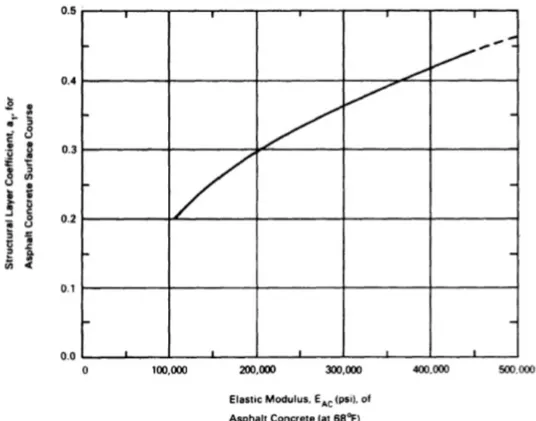
This approach to overlay design essentially requires that the total pavement structure be developed as a new design for the specified service conditions and then compared to the existing pavement structure (taking into account pavement condition, type, and thickness of the pavement layers). Current component design procedures require substantial judgment to effectively use them. This judgment is mainly associated with selection of "weighting factors" to use in evaluating the structural adequacy of the existing pavement layers (i.e., each layer of the pavement structure is assigned a layer coefficient often on the basis of experience).
!"<"#"!"#$$J-2K@+.3'&*34D+$A+.342G$L43B$M4H4342G$>+(:+*34-2$,'43+'4)$
Pavement surface deflection measurements can be used to determine pavement structural properties, which can then be used to determine the required amount of additional pavement structure. Essentially, a pavement's surface deflection in response to a known loading is used as a measure of effective strength. This "effective strength" is influenced by a variety of factors including material properties (including subgrade), thickness of pavement layers, and environmental effects. Most currently used deflection based overlay design procedures do not attempt to isolate material properties of individual pavement layers.
!"<"#"!";$$F+*B)24.34*K6H84'4*):$I2):E.4.$
Mechanistic-empirical based design methods are useful in overlay design as well as new pavement design. Their greatest advantage is the versatility provided in evaluating different materials under various environments and pavement conditions. Mechanistic-empirical procedures provide a basis for rationally modeling pavement systems. As these models improve, better correlations can be expected between design and performance parameters. In many places these procedures have replaced limiting deflection overlay methods, since the latter do not