School of Science
Department of Physics and Astronomy Master Degree in Physics
DEVELOPMENT OF THE SHiP
DOWNSTREAM MUON DETECTOR
Supervisor:
Prof. Tiziano Rovelli
Co-supervisors:
Dr. Alessandro Montanari
Dr. Nicol`
o Tosi
Submitted by:
Valentina Cicero
Academic Year 2018/2019SHiP (Search for Hidden Particles) is a beam dump experiment proposed at CERN SPS, currently in the design stage. SHiP aims to observe long lived particles very weakly coupled with ordinary matter, as expected in a large number of Hidden Sector models, that are able do describe Dark matter, neutrino oscillation and the origins of the Barionic Asimmetry of universe.
In this thesis the development of the SHiP Downstream Muon Detector is described. This subdetector aims to identify with high efficiency muons produced by signal processes and to distinguish them from neutrino- and beam-induced background ones. In order to effectively distinguish background events mistakenly reconstructed as signal vertexes due to their spatial overlapping, a time resolution better than 200 ps is mandatory. Therefore, it is extremely important that the detector components are optimized with respect to time resolution.
The detector employs active layers made of plastic scintillator tiles, each coupled to silicon photomultipliers (SiPM). This thesis focuses on the development of tile prototypes that are able to meet the detector time resolution requirements, through the study of various aspects of the tile design. The improved design defined with the contribution of this thesis work has become the current baseline design and will be tested with a prototype in early 2020 at the Frascati INFN Laboratories.
L’esperimento SHiP (Search for Hidden Particles) `e un esperimento di beam dump pro-posto all’SPS del CERN, al momento in fase di progettazione. L’obiettivo di SHiP con-siste nell’osservazione di particelle a lunga vita media accoppiate molto debolmente con la materia ordinaria, come previsto da un grande numero di modelli di Hidden Sector ca-paci di descrivere la materia oscura, le oscillazioni dei neutrini e le origini dell’asimmetria barionica nell’Universo.
In questa tesi `e descritto il lavoro svolto sullo sviluppo del rivelatore di muoni di SHiP, il cui scopo `e principalmente quello di identificare con alta efficienza i muoni provenienti da canali di decadimento di nuova fisica e di separarli da processi di background indotti da neutrini e dal fascio. Per discriminare efficacemente gli eventi di background ricostruiti erroneamente come vertici di segnale per via della loro sovrapposizione spaziale, `e nec-essario che la risoluzione temporale del detector sia inferiore ai 200 ps. Risulta quindi di estrema importanza l’ottimizzazione delle componenti del rivelatore in funzione della risoluzione temporale.
Il rivelatore impiega stazioni attive composte da tiles di scintillatore plastico, ciascuna accoppiata a fotomoltiplicatori al silicio (SiPM). Questo lavoro di tesi si concentra sullo sviluppo di prototipi di tiles che soddisfino i requisiti di risoluzione temporale del rivela-tore, per mezzo dello studio di diversi aspetti della tile.
Il design definito con il lavoro di questa tesi `e diventato l’attuale soluzione di riferimento e sar`a testato a inizio 2020 presso i Laboratori Nazionali di Frascati.
Introduction 1
1 Physics background 3
1.1 Theories beyond the Standard Model . . . 3
1.1.1 Vector portal . . . 5 1.1.2 Scalar portal . . . 6 1.1.3 Neutrino portal . . . 8 1.1.4 Axion-Like particles . . . 10 1.1.5 SUSY . . . 10 1.2 τ Neutrino Physics . . . 11
2 The SHiP Experiment 13 2.1 Overview . . . 13
2.2 CERN Beam Dump Facility . . . 14
2.2.1 Proton beam . . . 15
2.2.2 Target . . . 16
2.2.3 Muon shield . . . 17
2.3 Scattering and Neutrino Detector . . . 18
2.4 Decay Spectrometer . . . 20
2.4.1 Decay volume . . . 20
2.4.2 Surround Background Tagger . . . 21
2.4.3 Spectrometer Straw Tracker . . . 21
2.4.4 Timing Detector . . . 22
2.4.5 Electromagnetic calorimeter . . . 23
3 SHiP Muon Detector 25 3.1 Technical specifications and required performance . . . 25
3.2 Detector layout . . . 27
3.3 Active layer design . . . 28
3.3.1 Tiles . . . 29 3.3.2 Detector Module . . . 32 4 Scintillation detectors 35 4.1 Scintillators . . . 35 4.1.1 Inorganic Scintillators . . . 36 4.1.2 Organic Scintillators . . . 37 4.1.3 Plastic scintillators . . . 39
4.1.4 Plastic scintillators response . . . 40
4.2 Silicon Photomultipliers . . . 44
4.2.1 Working principle . . . 44
4.2.2 Performance parameters . . . 47
4.3 SiPM readout electronics . . . 55
4.3.1 Basic readout methods . . . 57
4.3.2 Common base amplifier . . . 58
5 Tile prototypes 61 5.1 Tile prototypes . . . 61
5.1.1 SiPM characterization for tile H . . . 65
5.2 Test beam experimental setup . . . 67
5.2.1 2018 CERN T10 test beam . . . 67
5.2.2 2019 DESY test beam . . . 70
5.3 Tile timing resolution . . . 71
5.4 Timing algorithms . . . 71
5.4.1 Constant Fraction Discriminator (CFD) . . . 71
5.4.2 Rising Edge Linear Fit . . . 72
5.4.3 Derivative method . . . 73
5.4.4 Algorithm optimization . . . 74
5.4.5 Best timing algorithm . . . 76
5.5 Trigger Optimization and timing resolution . . . 77
6 Experimental measurements and comparison with simulation 79 6.1 Tiles Timing Resolution . . . 79
6.1.1 CERN T10 test beam tiles . . . 79
6.1.2 DESY test beam tile . . . 81
6.2 Tile Simulation . . . 85
6.2.1 Simulated timing resolution and comparison with DESY tile . . . 87
6.3 Tile 10 ˆ 10 cm2 with slots . . . 88
6.3.2 Comparison between slot and glued corner . . . 90 6.4 New baseline design . . . 92
Conclusions 95
Bibliography 97
SHiP is an experiment aimed at exploring the domain of very weakly interacting par-ticles. It is designed to be installed downstream of a new high-intensity beam-dump facility at the Super Proton Synchrotron at CERN.
We have now observed all the particles of the Standard Model (except for the ντ), how-ever it is becoming clear that it cannot be the ultimate theory. Some yet unknown particles or interactions are required to explain a number of observed phenomena in particle physics, astrophysics and cosmology, such as dark matter, neutrino masses and oscillations, baryon asymmetry, and the expansion of the universe. While these phe-nomena are well-established observationally, they only give weak indications about the energy scale of the new physics. It is plausible that the shortcomings of the Standard Model may have their origin in new physics only involving very weakly interacting, rel-atively light particles. Experimentally, the opportunity presents itself as an exploration at the intensity frontier with the largest possible luminosity to overcome the very feeble interactions, and the largest possible acceptance to account for the typically long life-times. Beam-dump experiments are potentially superior to collider experiments in the sensitivity to GeV-scale hidden particles with their luminosities being several orders of magnitude larger than at colliders.
The SHiP experiment is composed of several subdetectors, of which the most downstream is dedicated to the identification of muons. The muon detector will cover an area of 72 m2 and will be equipped with 4 planes of scintillator interposed with iron absorbers. One of the main contributions to background in the experiment is given by uncorrelated muon tracks forming a fake vertex in the fiducial volume. This “combinatorial” background can be reduced by requiring the particles that form a vertex to be on time within a very short time window, and this drives the requirement of the detector time resolution. In order to cover such a large area with a fast and robust detector, a system based on „200 cm2 squared scintillator tiles, read out at the corners by silicon photomultipliers (SiPMs), has been developed. Through the optimization of the SiPM characteristics, placement and mounting technique on the tile, as well as coating type of the scintillator, we aim at achieving a time resolution lower than 400 ps on a tile of such size.
The work is organized as follows: the first chapter describes the theoretical background and the main physics goals of of the SHiP experiment. The second chapter is an overview of the experiment: the basic structure of the apparatus is explained, describing the target and the two main detectors, the first aimed at observing the interactions of neutrinos and dark matter, the other designed to detect the products of hidden particle decays. Chapter 3 is entirely dedicated to the description of the SHiP Downstream Muon De-tector. In the fourth chapter I describe in detail the working principles of the Muon Detector basic elements: a tile made of plastic scintillator read out by silicon photomul-tipliers. Finally, Chapters 5 and 6 are dedicated to the testing of the prototype tiles built between 2018 and 2019 in order to develop a definitive design of the scintillator tile. In chapter 5, I examined the data collected in 2018 with the available prototypes, and used it investigate the most suitable algorithms to extract timing information from the tile output. The results obtained on the tiles timing performance led us to build an improved prototype. I characterized the silicon photomultipliers to be installed and analyzed the data of the beam test performed in 2019. The analysis for determining the time resolution of the prototypes is described in chapter 6, with the comparison with simulations as well. Moreover, I explored an alternative method to mount silicon pho-tomultipliers to the scintillator that is mechanically more convenient by comparing the light collection of the two methods.
The analyses carried out in this thesis will define a new tile design that will be tested in early 2020.
Physics background
1.1
Theories beyond the Standard Model
As of 2012, with the discovery of the Higgs Boson, all predicted constituents of the Standard Model (SM) have been observed. At the same time, no significant deviations from the SM were found in direct or in indirect searches for new physics. For a value of the Higgs mass of » 125 GeV, the SM may remain mathematically consistent and valid as an effective field theory up to a very high energy scale, possibly to the scale of quantum gravity, the Planck scale. However, the Standard Model cannot be considered a complete description of Nature, since it does not explain some experimental evidences. The most relevant are the following:
1. Neutrino oscillations show that neutrinos have mass different from zero, but how they acquire mass is still unknown. If they behave like the other elementary fermions, they should acquire mass through the Yukawa coupling to the Higgs field, however, this is not possible as a right-handed neutrino is needed, not foreseen in the original version of the SM. The introduction of a right-handed field νR would allow to form a Dirac mass term generated by coupling to the Higgs field, as it occurs for quarks and charged leptons, through the so-called see-saw mechanism [1]. In the Neutrino Minimal Standard Model (νMSM), the right handed neutrinos can have masses also below the EW scale and extremely feeble couplings [1];
2. it was estimated that ordinary matter accounts for only 5% of the total composition of the Universe. The remaining consists of „ 68% Dark Energy and „ 27% of Dark matter. Dark matter does not interact with the electromagnetic force, but it has a gravitational effect that has brought to its discovery. Dark Energy seems to be related to the vacuum in space: it does not have any local gravitational effects,
but a global effect on the Universe as a whole, thus influencing the expansion rate of the Universe itself;
3. the Baryon Asymmetry of the Universe (BAU) consists in the excess of matter over anti-matter in the Universe. The existence of matter itself is the indirect proof that there must have been a slight matter-antimatter imbalance in the early Universe, of the order of one particle per billion. The SM cannot explain this imbalance, as the observed CP violation, which occurs through the CKM mass matrix, is too small (εCP „ 10´20) to account for the observed value of the baryon asymmetry (ηB “
nB´nB
nγ ” 10
´10, n
B, nB being respectively the baryon and anti-barion density and nγ the photon density).
There is also no consensus on a mechanism to account for cosmic inflation.
There is a list of aspects that need to be investigated to produce an extension of the SM that includes them, but no clear guidance on the scale of any new physics, or the coupling strength of any new particles to the SM ones. This lack of theoretical guidance needs experimental searches at both the “energy” and “intensity frontiers”. One possibility is that the hypothetical particles are heavy and require even higher collision energy to be observed. Major particle physics experiments of the last few decades, including LEP and LHC at CERN, and Tevatron in the US have pursued this path. Another possibility is that our inability to observe new particles lies not in their heavy mass, but rather in their extremely feeble interactions with the SM particles, which make them dark or hidden. If true, this would imply that to detect them we should maximise the number of interactions, instead of the center-of-mass energy. This latter choice is the main motivation for beam dump experiments, which belong to the intensity frontier category. A scheme of a typical beam dump experiment is shown in Fig. 1.1: a beam of high energy protons impinges onto a dense target (beam dump), which absorbs it giving rise to a lot of interactions and final state particles. The high number of interactions allows the production of light new particles, even considering their feeble couplings to Standard Model particles. The new particles are let to decay in a long vacuum volume, called the decay volume, at its end the charged particles produced are identified in a detector and their characteristics are measured. As well as the hidden particles, SM particles are also produced in the dump; rejection of those particles is essential to suppress backgrounds. In particular, a significant amount of muons are produced. Thus, it is necessary to install shields and veto counters between the dump and the decay volume. Additional veto counters surrounding the detector serve to reject background events coming from outside the detector.
Some of the new particles can be heavy or do not interact directly with the SM sector. These “hidden sectors” may be accessible nevertheless to the intensity
fron-Figure 1.1: Schematic design of a typical beam dump experiment.
tier experiments via sufficiently light particles, which are coupled to the SM sectors either via renormalizable interactions with small dimensionless coupling constant (called ”portals”) or by higher-dimensional operators suppressed by the dimensionful couplings, corresponding to a new energy scale of the hidden sector. For the Standard Model, renormalizable portals can be classified into the following three types, depending on the mass dimension of the SM singlet operator.
1. Vector portal : the singlet operator has the dimension of a mass squared (GeV2). The new particles are Abelian fields which couple to the hypercharge field FYµν via a dimensionless coupling, characterizing the mixing between the new vector field with the Z-boson and the photon;
2. Scalar portal : the new particles are neutral singlet scalars that couple to the square of the Higgs field;
3. Neutrino portal : new neutral singlet fermions Niare introduced, which couple with singlet operators with dimension GeV52
The phenomenology of these portals and other possible models will be discussed in more detail in the following sections.
1.1.1
Vector portal
The gauge structure of the Standard Model, the SU p3q ˆ SU p2q ˆ U p1q combination, can be derived from a larger gauge group, as is the case in Grand Unified Theories (GUTs). In that case, one expects that at least several of the new vector states are very heavy, well beyond the direct reach of accelerators. However, if additional gauge structures accompany the SM, as is the case of multiple U(1)s, SU p3q ˆ SU p2q ˆ rU p1qsn, sub-TeV
gauge bosons are also allowed.
The LHC set robust bounds on these new vector states [2]. An alternative possibility, relatively light vector states (e.g., in the GeV mass range) with small couplings to the SM, is instead poorly constrained by the LHC experiments and represents an attractive physics target for many experiments at the intensity frontier.
The simplest way to couple a new vector particle to the SM is to use the kinetically-mixed portal. In this case, none of the SM fields needs to be charged under the new gauge groups. Minimalistic models consider a U(1) gauge symmetry in the hidden sector with an associated gauge boson A’, called dark photon.
If a new Higgs field is present in the dark sector (dark Higgs), then the U(1) gauge symmetry might be broken by a Higgs-like mechanism and the dark photon acquires a non-zero mass.
The vector portals are of great interest because they might help to solve known problems of the SM. Light mass vector particles might provide a solution to the muon g-2 discrep-ancy [3] through a slightly extended model of the dark photon [4]. Light mass vector particles can also be thought of as mediators of the interaction with DM and provide an explanation to the astrophysical positron excess [5].
In a beam dump experiment, dark photons can be originated via:
1. Meson decays: mesons are copiously produced in proton on target collisions. The most important process is π0
ÝÑ γA , which is suppressed by ε2, the ! 1 mixing parameter between the dark photon and the SM one, but not by α, since the π0 decay is an electromagnetic process;
2. Proton bremsstrahlung: the (quasi)elastic scattering of incident protons on nucleons in the target can lead to the production of vector states via bremsstrahlung process pp ÝÑ ppA;
3. Direct perturbative QCD production: processes like q ` q ÝÑ A and q ` g ÝÑ q ` A become dominant for larger masses of the vector particles.
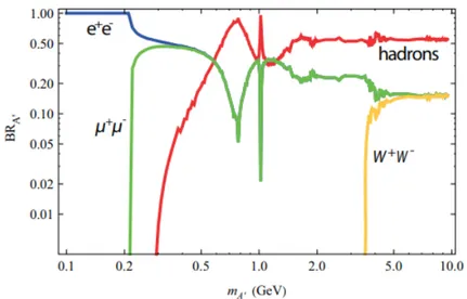
The decay modes and branching ratios of dark photons are shown in Fig. 1.2 in relation to the potential dark photon mass.
1.1.2
Scalar portal
Many extensions of the SM Higgs sector foresee additional light scalar or pseudoscalar particles that are singlets under the SM gauge group and have highly suppressed cou-plings to SM particles. Alternatively, such particles can arise as pseudo-Nambu-Goldstone bosons (PNGB) of a spontaneously broken symmetry [7].
Figure 1.2: Predicted dark photons decay modes and their branching fractions for dif-ferent dark photon mass values. [6]
There are already stringent experimental constraints on the mass of hidden scalars and their coupling g˚ to SM particles. Nevertheless, the SHiP experiment will give new in-sights especially for the mass region below 10 GeV, that is as of today still unexplored. This model is build from the SM Lagrangian with the addition of a (CP-even) singlet scalar field: L “ LSM` 1 2BµSB µ S ` pα1S ` αS2qpH:Hq ` λ2S3` λ3S3` λ4S4 (1.1) where λ1,2,3 are the scalar self couplings while α1 and α represent the portal couplings to the SM Higgs doublet H.
For a hidden sector made of scalar fields, the portal operators appearing in Eq. (1.1) are renormalizable, meaning that if the interactions between the extra scalar and the Higgs boson are generated at very high scales such as the GUT, or even Planck scale, then they may remain as a relevant interaction down to the energy scales probed by experiments today. Moreover, since dark matter is believed to be neutral under all SM gauge interactions, and the Higgs portal can provide a bridge between the SM and neutral sectors, it is possible that scalars coupled through the Higgs portal may play a role in dark sector physics, or perhaps themselves be DM candidates.
a small α1 coupling, the mixing angle is given by [2]: g˚ “ sinθ ” θ ” α1v2 m2 h (1.2)
where v “ 246 GeV denotes the electroweak vacuum expectation value (VEV). In this case, both the production mechanisms and decay modes coincide with those of a SM Higgs boson having the same mass of the considered light scalar. However, with respect to the Higgs boson, the production cross sections and the decay rates are suppressed by a factor g2
˚. Figure 1.3 shows the decay branching ratios as a function of the scalar mass mS, the gap around 2 GeV is due to the appearance of a large number of hadronic resonances.
Figure 1.3: Decay branching ratios function of the scalar mass ms
1.1.3
Neutrino portal
The Neutrino Minimal Standard model (νMSM) [8, 9] is a minimalistic model that solves the SM puzzles by inserting three heavy right-handed neutrinos that couple to the left-handed SM neutrinos (see Fig. 1.4). These heavy neutrinos are sterile, i.e. they do not couple, apart from gravity, to any of the fundamental SM interactions, and are also referred to as Heavy Neutral Leptons (HNLs).
HNLs are singlets with respect to the SU p2q ˆ U p1q group and they couple to the Higgs boson.
Figure 1.4: In the Standard Model neutrinos are massless and always left-chiral. The right-chiral counterparts N1, N2, N3 are added. They do not feel the electric, weak or strong forces (thus sterile neutrinos).
The lightest of the HNLs, N1, is extimated to have a mass of a few keV [8], and it is a DM candidate with a lifetime bigger than the lifetime of the Universe. It can decay either in three neutrinos (invisible) or in a photon and a neutrino (N1 ÝÑ νγ). On the other hand, N2 and N3 are degenerate in mass, in the MeV-GeV range. They can explain the baryon asymmetry through a process of leptogenesis made possible by their lepton number violating Majorana mass term. Furthermore, they can explain the observed pattern of neutrino masses through the type I see-saw mechanism [9].
HNLs can be produced in association with a charged lepton in 2-body meson decays, and in 3-body meson decays into HNL, light (pseudoscalar or vector) meson and a charged lepton [2]. A possible HNL production mechanisms is shown in the left panel of Fig. 1.5.
Figure 1.5: Production (left) and subsequent decay (right) of the particle NI
It is exactly their mixing with active neutrinos through the Higgs boson that makes them unstable. They decay emitting a charged lepton and a vector boson (W or Z)
giving rise to final states containing either another charged lepton or hadrons:
Ni ÝÑ e`e´ν, µ`µ´ν, µ˘e¯ν, τ`τ´ν, etc. (1.3)
Ni ÝÑ π˘e¯, π¯µ¯, K˘e¯, K˘π¯, etc. (1.4) A potential two-body decay mode of N2,3 is shown in the right panel of fig. 1.5.
1.1.4
Axion-Like particles
While the new particles hypothesized by the models described in the previous sections are coupled to the SM via renormalizable interactions with small dimensionless coupling constants, Axion Like Particles (ALPs) would couple via a higher-dimensional operator [2].
ALPs are Pseudo-Nambu-Goldstone bosons (PNGBs) that come from spontaneously broken global symmetries. They exhibit two fundamental properties: they have small couplings, as their interactions are suppressed by the scale of spontaneous symmetry breaking fA, and have a small mass, since a small explicit breaking of the symmetry at a scale Λ leads their mass to be suppressed by the scale of spontaneous symmetry breaking, i.e. mA» Λ2{fA.
An example of a very light PNGB is the axion, that was introduced to solve the strong CP problem in QCD. The axion mass is strongly constrained by theory. However, there are other possible particles that, even if they undergo very similar interactions with respect to the axion, they can have different masses. These particles are usually denoted as Axion-Like Particles. According to the models, each process that produces pions has a non-null probability of producing an axion. Particularly interesting channels to look for an axion decay are A ÝÑ γγ, to investigate for couplings with gauge bosons, and A ÝÑ µ`µ, to explore couplings with SM fermions.
1.1.5
SUSY
Supersymmetry (SUSY) is one of the most motivated extensions of the SM where bosons and fermions are connected. The minimal supersymmetric model considering only the minimum number of new particle states and new interactions consistent with phenomenology is the Minimal Supersymmetric Standard Model (MSSM) [10].
A supersymmetric transformation changes a bosonic state in a fermionic one and vice-versa: each fermion has a bosonic partner with the same quantum numbers but with a spin which differs by half a unit. Therefore, in the MSSM there are both vector super-fields associated with the Standard Model gauge groups which contain the vector bosons
and associated gaugino and chiral superfields for the SM fermions and Higgs bosons with their respective superpartners.
If the supersymmetry were an exact symmetry, all the particles belonging to the same supermultiplet should have the same mass. Hence, we should have been able to observe an s-electron with the same mass of an electron, a squark u with the same mass of the quark u and so on. Since any of these observations have not been done yet, the super-symmetry must be a broken super-symmetry.
The most general supersymmetric Lagrangian contains terms violating both the barion and the lepton number, thus being in contrast with the nonobservation of proton decays. To explain the stability of the proton, the MSSM imposes a new discrete symmetry named R-parity, which associates to a particle or its supersymmetric partner with spin s the quantic number R “ p1q3pBLq`2s [10]. R-parity is a multiplicative quantic number which is also assumed to be conserved in the physical processes.
Searches for Supersymmetry are now spanning the mass region of 100 GeV - 10 TeV and are currently ongoing at LHC. However, the possibility that SUSY particles have a mass which is a couple of orders of magnitude lighter than the mass of the W and Z bosons has not yet been excluded neither from LHC searches nor from precision fits of the SM. There are indeed many supersymmetric models that still allow for new light neutral particles to be in the MeV to a few GeV range that can be looked for at a beam dump experiment. For example, even though a stable neutralino in the mass range between 0.7 eV and 24 GeV is excluded because it gives too much DM, if the possibility of the R-parity to be violated is introduced then it becomes allowed. Not having a convincing theory of supersymmetry breaking leaves a lot of space for experiments to investigate.
1.2
τ Neutrino Physics
In a fixed target facility, with a high intensity and high energy proton beam impinging on a target, a high flux of neutrinos of all flavours can be expected. Therefore, it is ideally suited to perform studies on neutrino and antineutrino physics [7].
First direct measurements of tau neutrino charged current interactions are very recent, and no ντ interaction has been directly observed yet.
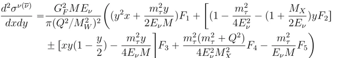
Search for ντ and ντ interactions shall lead to new measurements of the neutrino and antineutrino charged current cross sections. In a deep inelastic events’ analysis, the tau neutrino and antineutrino cross sections, in terms of the structure functions(F1 F5), can be written as:
d2σνpνq dxdy “ G2FM Eν πpQ2{M2 Wq2 ˆ py2x ` m 2 τy 2EνM qF1 ` „ p1 ´ m 2 τ 4E2 ν ´ p1 ` MX 2Eν qyF2s ˘ rxyp1 ´ y 2q ´ m2 τy 4EνM F3` m2 τpm2τ` Q2q 4E2 νMX2 F4´ m2 τ EνM F5 ˙ (1.5)
where the plus sign applies to neutrino scattering and the minus one to antineutrino scattering. M and mτ are the nucleon and τ lepton masses, respectively, MW is the W boson mass, Eν is the initial neutrino energy and GF is the Fermi constant. The structure functions F4 and F5, negligible in electron and muon neutrino interactions due to the factor m2
l{pEνM q, are relevant in ντ scattering and therefore can be measured only with ντ interactions. In figure 1.6, the expected cross sections for CC neutrino and antineutrino interactions are shown, assuming for F4 and F5 the values given by the SM, compared with the hypothesis F4 “ F5 “ 0 [11]. Neglecting both structure functions leads to an increase of the cross sections and, consequently, to a larger number of expected ντ and ντ interactions. The difference between the two hypotheses is greater at low energies and tends to zero beyond hundreds of GeVs, where the contribution of F4 and F5 becomes negligible.
Figure 1.6: Prediction of the Standard Model (shown as a solid curve) and in the F4 “ F5 “ 0 hypotheses (shown as a dashed curve) for ντ (on the left) and ντ (on the right) CC deep inelastic scattering cross section.
The SHiP Experiment
2.1
Overview
SHiP (Search for Hidden Particles) is a proposed beam dump experiment, whose primary goal is to explore hidden sector and tau neutrino physics [11]. 400 GeV protons, extracted from the Super Proton Synchrotron (SPS) accelerator, will impinge on a target made of molybdenum and tungsten. The SHiP detector, immediately downstream of the target, (Fig. 2.1) incorporates two complementary apparatuses, the Scattering and Neutrino Detector (SND), and the Decay Spectrometer: the first designed for the detection of neutrino interactions and light dark matter scattering off electrons and the second is optimized to detect the decay products of new particles.
Figure 2.1: Overview of the SHiP experiment. [12]
Proton interactions in the target give rise to a copious direct production of Standard Model particles, which form the background that must be suppressed. A hadron stopper
of approximately five meters of iron is enough to absorb the hadronic and electromagnetic showers emerging from the target, but it cannot stop a large flux of muons and neutrinos, produced by the decays of pions and kaons. The reduction of the muon background is the task of a dedicated 35 m long muon shield, based on the magnetic deflection of these charged particles in the horizontal plane.
The SND detector is inspired by the concept of the OPERA apparatus, which employs the Emulsion Cloud Chamber technology [11]. It will be able to detect the interactions with micrometric accuracy, measure the neutrino flavor and discriminate between neutrinos and antineutrinos.
The Decay Spectrometer is placed downstream of a 50 m long decay volume, whose length has been chosen in order to maximize the acceptance to the hidden particle decays products. This volume must be under vacuum, in order to minimize the background from the residual neutrino flux. The most downstream section of the apparatus is devoted to the detection of the hidden particle decay products, through a magnetic spectrometer to measure the particles momentum and charge and a calorimeter and muon detector for energy measurement and particle identification.
In this chapter, we shall give an overview of the main components of the SHiP apparatus, describing their basic structure and functionality. Chapter 4 is entirely dedicated to the design of the Downstream Muon Detector, whose development is the subject of this thesis.
2.2
CERN Beam Dump Facility
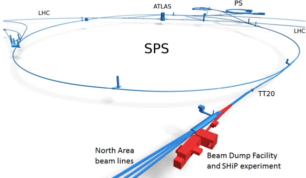
The SPS is a particle accelerator at CERN. With a 7 km circumference, it is the second-largest machine in the CERN accelerator complex. Today, it is used as the final injector for high-intensity proton beams for the Large Hadron Collider (LHC), but it also provides proton beams for different fixed-target experiments, such as COMPASS, NA61/SHINE and NA62. SHiP is designed to use protons of the SPS impinging on a thick target (beam dump). The project foresees the construction of the SHiP facility at the CERN Prevessin Site, on the North Area of the SPS accelerator complex, in a geographical location that allows a full integration on the CERN land with minor impact on the existing facilities. The proton beam is acted via the TT20 transfer line, shared with the other North area facilities. In Fig. 2.2, the proposed location of the SHiP facility at the CERN Prevessin site is shown in a schematic drawing.
Figure 2.2: SHiP facility location in the North Area at the SPS accelerator complex.
2.2.1
Proton beam
For the SHiP physics program, a 400 GeV/c proton beam is required to be delivered on the SHiP target [2]. Being the weakly coupled particles, foreseen in different models beyond the Standard Model, mainly produced in the decay of charmed hadrons, the choice of 400 GeV energy protons fits the requirement of a high charm production cross-section. The physics sensitivity of the experiment is based on acquiring a total of 2 ¨ 1020 protons on target. The operational mode consists of continuous 24-hour data taking throughout the operational year with the exception of maintenance during technical stops.
The procedure used to transfer high energy particles from the SPS circular accelerator to the TT20 linear beamline is done first with a set of extraction sextupoles that cause the particles in the beam to move from the stable area in the phase space to an unstable, but controlled, one, away from the beam core. An electrostatic septum then catches the most unstable protons and deflects them toward the extraction line. Once the majority of the protons have been consumed, a new beam is injected and accelerated. The particle beam extracted is usually referred to as a spill. Each spill is assumed to have a beam intensity of 4 ˆ 1013 protons on target, spread out over 1 s.
A new dedicated SHiP beam line branches off at the top of the TT20 transfer line, to the TDC2 cavern, with the help of a set of newly proposed magnet splitters which will replace the current one. The SHiP beam line is 120 m long and entirely in the horizontal plane. Bending magnets and a set of quadrupoles are used to minimize dispersion and to suppress motion induced by momentum variations during extraction.
2.2.2
Target
The SHiP production target is one of the most challenging aspects of the facility due to the very high average beam power (up to 350 kW) deposited on the target [11]. Inte-grating only over the spill duration, the expected beam power is 2.56 MW.
The choice of materials must take into account not only the high energy deposited and the high temperatures reached, but also the physics that is performed at SHiP. To search for Hidden Particles mainly coming from heavy mesons, their production must be maxi-mized, while the fraction of neutrinos and muons coming from pion/kaon decays must be reduced as much as possible. These requirements lead to the choice of a high A material and with the shortest possible nuclear interaction length for pion and kaon reabsorption from spallation [13]. While a Tungsten target would be an optimal candidate that satis-fies these material requirements, it cannot sustain the high temperatures reached during the steady state of operations.
The required performance is achieved with a longitudinally segmented hybrid target consisting of blocks of five interaction lengths of titanium-zirconium doped molybdenum (TZM) alloy in the core of the shower followed by seven interaction lengths of pure tungsten. The blocks are interleaved with slits of 5 mm thickness for water cooling. In order to respect the material limits on the thermomechanical stresses, the thickness of each slab together with the location of each cooling slit has been optimized to provide a uniform energy deposition and to guarantee sufficient energy extraction. Figure 2.3 shows the target design. The target shape is cylindrical, with a diameter of 25 cm and a length of 1.5 m, to maximize the shower containment.
The target is embedded in a massive cast iron bunker (440 m3), with an inner core consisting of water-cooled cast iron blocks with embedded stainless steel water cooling pipes. The downstream proximity shielding which has a thickness of 5 m also acts as a hadron stopper. The hadron stopper has the double objective of absorbing the secondary hadrons and the residual non-interacting protons emerging from the target, and to significantly reduce the exposure of the downstream experiment muon shield to radiation. Moreover, the iron of the hadron stopper has been magnetised over a length of 4 m with the help of a magnetic coil integrated into the shielding [14]. The applied
Figure 2.3: Target configuration.
dipole field makes up the first section of the muon shield, which is illustrated in the next section.
2.2.3
Muon shield
The protons that impinge on the target produce about 5 ¨ 109 muons/spill [14]. These muons represent the main source of background to the detection of rare events, hence their flux has to be reduced by several orders of magnitude over the shortest possible distance, so that the transverse size of detector can be smaller to cover a given solid angle. To clear a 5 m horizontally wide region, a 35 m long active muon shield based on magnetic deflection of the muons in the horizontal plane is introduced right after the hadron stopper [12]. The design of the muon shield is shown in 2.4.
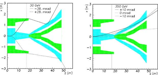
The first section, that is the 4 m long dipole field inside the hadron stopper, is used to separate µ` and µ´ on opposite sides, regardless of their initial direction. A two-dimensional scheme with the magnets behaviour is shown in Fig. 2.5. The field orientations are shown by the two colours: the regular field is depicted in light blue, while the return field is green. In the second section of the muon shield, the field polarization is reversed, with the return field closer to the z axis and the regular field at larger x. Muons bent out by the first part of the shield are then bent further outward, rather than back towards detector, as it would happen if a single long sequence of magnets were used. The peculiar shape of the final part of the shield allows to bend out also those particles which have not been deflected in the first part of the shield.
Figure 2.4: Three dimensional view of the active shield.
Figure 2.5: Horizontal view of the proposed active muon shield showing the trajectory of three 30 Gev (left) and 350 GeV (right) muons with a range of initial angles. The light blue and green show the regions of regular and return field respectively [11]
2.3
Scattering and Neutrino Detector
The detector of neutrino and dark matter interactions, whose layout is shown in Figure 2.6, is placed downstream of the muon shield. A 7 m long magnet, providing a 1.2 T horizontal magnetic field, hosts the Emulsion Target interleaved with Target Tracker planes, and a Downstream Tracker [14].
Chamber (ECC) made of lead plates interleaved with nuclear emulsion films, followed by a Compact Emulsion Spectrometer (CES) for the momentum and charge measurement of particles produced in neutrino interactions. The ECC bricks are arranged in walls alternated with Target Tracker planes, based on scintillating fibers technology, which provide the time stamp of the interactions occurring in the target.
The Downstream Tracker is made of three Target Tracker planes separated by 50 cm air gaps. It is used to measure the charge and momentum of muons exiting the target region, thus extending significantly the detectable momentum range of the CES. The Downstream Tracker planes also help to connect the tracks in the emulsion films with the downstream muon identification system.
The muon identification system is made of a sequence of iron filters and RPC planes, totalling about two metres in length. The system also has the role of tagging neutrino interactions in its material which could lead to long-lived neutral particles entering the downstream HS decay volume and mimicking signal events.
Figure 2.6: Layout of the scattering and neutrino detector. [14]
The main aim of this detector is to study neutrino tau interactions: as discussed in Section 2.2, only a few ντ interactions have been detected by previous experiments and no ντ has been observed yet. The SHiP experiment plans to achieve the first ob-servation of a ντ interaction and to analyse tau neutrino interactions with a statistics three orders of magnitude larger than past experiments. In addition, observing the production of charmed hadrons in antineutrino interactions will provide precise knowl-edge of the strangeness component in the nucleon, because this production mode selects
anti-strange quark in the nucleon, whereas the presence of valence quarks in neutrino scattering makes the contribution of the d-quark compelling [2]. On the other hand the same detector may observe scattering of light dark matter, thus providing signals of new physics beyond the Standard Model.
2.4
Decay Spectrometer
The SHiP Decay Spectrometer (right part of Fig. 2.1) consists of the decay volume, the Surrounding Background Tagger (SBT), the Spectrometer Straw Tracker (SST), to-gether with the large spectrometer magnet with a total field integral of about 0.5 Tm, the Timing Detector (TD), the Electromagnetic Calorimeter and the Downstream Muon Detector [11].
The Decay Spectrometer has to perform precise measurements of charged particles and photons originating from decay vertices of hidden particles in the decay volume, mea-sure their momenta and energies, and provide PID information. Moreover, the Decay Spectrometer has to ensure a redundant background suppression using timing and track information from the TD and the SST, vetoing criteria from the upstream muon system of the SND and the SBT, and PID by the calorimeter and the muon systems.
2.4.1
Decay volume
Deep inelastic neutrino-nucleon scattering in the detector volume leads to background events through the production of V0 particles (KL, KS, Λ) whose decays mimic the topology and modes of the hidden particle decays. With 2 ˆ 1020 protons on target, a flux of „ 4.5 ˆ 1018 neutrinos and „ 3 ˆ 1018 anti-neutrinos is expected within the angular acceptance of the SHiP detector [11].
In order to suppress neutrino-induced background events in the fiducial decay volume, the experiment vacuum vessel is kept at a pressure of 1 mbar. In this configuration, neutrino interactions mainly occur in the vessel walls, where they can be easily rejected by using criteria based on the reconstructed impact parameter at the proton target. Residual neutrino interactions, as well as muon deep inelastic interactions with the vessel structure, are further suppressed by the Surrounding Background Tagger system, which is covering the entire decay volume and is capable of detecting the associated activity. The SHIP vacuum vessel consists of two parts, the volume in which a decay vertex is accepted, and the spectrometer section. The spectrometer section runs through the spectrometer magnet and includes four tracker stations, which are symmetrically located with two stations upstream and two downstream of the magnet. An upstream and a downstream end-cap close off the ends of the vacuum vessel. As shown in Fig. 2.7,
the shape of the decay volume is a pyramidal frustum, with upstream dimensions of 2.2 ˆ5.0 m2, downstream dimensions of 5.9 ˆ11.9 m2 and length of 50 m [12]. The length of the decay volume is mainly defined by maximizing the acceptance to the different HS decay products given the transverse aperture of the spectrometer.
Figure 2.7: Overview of the structure of the decay volume showing the compartmental-ization for the Surrounding Background Tagger.
2.4.2
Surround Background Tagger
The SBT detects charged particles either entering the vacuum vessel from outside or produced in the inelastic interactions of muons and neutrinos in the vacuum vessel walls. The SBT is sub-divided into individual cells integrated into the support structure of the vacuum vessel, each filled with a liquid scintillator consisting of linear alkylbenzene (LAB) together with 2.0 g/l diphenyl-oxazole (PPO) as the primary fluor (see Ch. 4). The cell size is 80 cm in the longitudinal direction and typically 120 cm in the transverse direction, depending on the location along the vacuum vessel. The compartmentalization of the SBT is shown in Fig. 2.7. The thickness of the liquid scintillator layer, surrounding the walls of the complete decay volume is about 30 cm, again varying along the length of the vacuum vessel. Each cell of the SBT is read out by two wavelength-shifting optical modules (WOM) that detect scintillation light in the range of 340 nm - 400 nm and transport the light to a ring of Silicon Photomultipliers directly coupled to the WOM tube.
2.4.3
Spectrometer Straw Tracker
The purpose of the Spectrometer Straw Tracker (SST) is to measure track parameters and momentum of charged particles with high efficiency and enough accuracy to recon-struct decays of hidden particles, and to reject background events. The precision of the
extrapolated position of the tracks must be well matched with the segmentation of the timing detectors such that the high accuracy of the associated track time can be used to remove combinatorial background. The invariant mass, the vertex quality, the timing, the matching to background veto taggers, and the pointing to the production target are crucial tools for rejecting background from spurious V0 meson decays or from random combinations.
The spectrometer consists of a large aperture dipole magnet and two tracking telescopes on each side of the magnet. Four tracking stations are symmetrically arranged around the dipole magnet, as depicted in Fig. 2.8. The four stations are identical with a nominal acceptance of 5 ˆ 10 m, and are based on ultra-thin straw drift tubes oriented horizon-tally. Each station contains four views, in a Y-U-V-Y arrangement, where U and V are stereo views with straws rotated by a small angle ˘θstereo around the z-axis with respect to the y-measuring straws. The straw tubes are made of thin polyethylene terephthalate (PET), as the tracking stations must minimise the contribution from multiple scattering, and are 5 m long, with a diameter of 20 mm [12].
The B field is about 0.14 T at its maximum and about 0.08 T at the location of the clos-est tracker stations, just outside the magnet. On the longitudinal axis the field integral between the second and third station is approximately 0.65 Tm.
2.4.4
Timing Detector
Background muons entering the vessel can potentially cross within the vertex recon-struction resolution and produce fake signals. One efficient way to distinguish random crossings from genuine physics events is to require the measured particle signals in the SHiP spectrometer to be coincident in time. In order to reduce combinatorial di-muon background to an acceptable level, a timing resolution of 100 ps is necessary. This re-quires the use of a dedicated timing detector placed in front of the calorimeter.
There are currently two options under investigation for this timing detector: plastic scin-tillators and multigap resistive plate chambers (MRPCs).
The design of the spectrometer timing using plastic scintillators consists of three columns of 182 horizontal bars with dimensions 168 cm ˆ6 cm ˆ1 cm, with 0.5 cm overlap be-tween bars, for a total area of 5 m ˆ 10 m. Each bar is read out on both sides by an array of eight 6 mm ˆ 6 mm SiPMs. [12]
The alternative design is based on the timing Resistive Plate Chamber (tRPC) tech-nology. The sensitive module is confined inside a completely sealed plastic box to ease the construction and allow operation with a low flux of gas. The chambers are made of stacks of glass plates, separated by 0.3 mm nylon mono-filaments. The outer glass plates are coated with resistive paint, and act as high voltage electrodes, while the inner ones
Figure 2.8: Position of the tracking stations and dipole magnet, overlaid with magnetic field component Bx as a function of z.
are left electrically floating. Signals induced by charged particles traversing the chamber are collected on segmented readout strips which lie along the x axis: the y coordinate of the incoming particle is therefore obtained directly from the fired strip while the x coordinate is derived from the average of the times registered on each end of the strips [11].
2.4.5
Electromagnetic calorimeter
The SHiP calorimeter handles a number of tasks. It must identify photons, electrons and π0 mesons and provide measurements of their energies and positions. Furthermore, the calorimeter must contribute to the identification of charged pions and muons and to provide precise time information for event reconstruction. Electron/pion identification is necessary for the separation of HN L ÝÑ e ˘ π¯ decays from the main background channels such as K0
S ÝÑ π`π and KL0 ÝÑ π`π´π0. Good photon identification and energy measurements are necessary for the correct reconstruction of the π0s for several channels. For example, the reconstruction of the HN L ÝÑ l˘ρ¯
where l˘ denotes electron or muon, and for channels involving decays of light mesons with photons in the final state. For the HN L ÝÑ l˘π¯π0 channel, the main background is K0
LÝÑ π`π´π0, which has a branching ratio of 12.5%, that can also be rejected with a precise invariant mass measurement [2]. It is therefore necessary to have an optimal calorimeter energy resolution giving an invariant mass resolution similar to that given by tracking. The calorimeter system also aids in pion/muon discrimination and in the identification of muons, especially in the low momentum region (p ă 5 GeV/c) where a sizeable fraction („ 14%) of muons from a 1 GeV/c2 HNL can be produced but they may not reach all the sensor planes of the muon detector.
The calorimeter is placed at the end of the vacuum vessel right after the timing detec-tor. Its design consists of a 25 X0 long sampling calorimeter, with lead absorber plates orthogonal to the proton beam direction, and with two kinds of active layers [15]. Most sampling layers are equipped with scintillator bars read out by WLS fibres with a rela-tively coarse spatial segmentation. The lead absorber plates are 0.5 X0 thick, i.e. 0.28 cm, while the scintillator is 0.56 cm thick. Three high resolution gas detector layers, 1.12 cm thick, one located after 3 X0 and the other two around the shower maximum at 10 X0 and 13 X0 , to cover the range for both low and high energy showers, will determine the transverse position of the shower at the three depths and allow for reconstruction of the photon angle. To obtain a desired performance of few mrad angular resolution, the three high resolution active layers need to have a high spatial segmentation of about 200 µm, that can be achieved with micro-pattern gas detectors or alternatively scintillating fibre detectors.
The Muon Detector is placed downstream the electromagnetic calorimeter. Its design is described in detail in the next chapter.
SHiP Muon Detector
3.1
Technical specifications and required performance
The muon system is placed downstream of the calorimeter system. The detector is mainly responsible for identifying muons with high efficiency and for discriminating them from pions escaping the calorimeter.
These particles are originated in signal processes [2], such as:
• HN L ÝÑ π`µ´ and HN L ÝÑ µ`µ´ν
µ in the neutrino portal; • V ÝÑ µ`µ´ in the vector portal;
• S ÝÑ µ`µ´ in the scalar portal;
that need to be distinguished from ν´ and µ´induced backgrounds, consisting mostly of KL ÝÑ π˘µ¯νµ and KS ÝÑ π`π´ decays originating in the material surrounding the decay volume.
Random combinations of beam-induced muons that escape the hadron absorber and the active filter can form a fake vertex inside the decay volume and mimic HN L ÝÑ π`µ de-cays if one of the two muons is misidentified as pion. These are typically high momentum tracks, so the particle identification system has to minimize the µ ÝÑ π misidentification probability in the entire interesting momentum range.
This background can be reduced by applying a timing cut [11]. In fact, beam-induced muons are uniformly distributed over the spill duration („ 1 s) while the decay products of long-lived particles arrive almost simultaneously at the spectrometer. The probability that two combinatorial muons mimic a decay of a long lived particle depends linearly on the time window in which the arrival times of the two muons are recorded. By requir-ing a tight (ă 1ns) time coincidence of candidate muon tracks, the muon system can
contribute to the rejection of the combinatorial background, and its effectiveness scales with the time resolution of the detector.
The momentum interval covered by the muon system ranges from „2.6 GeV/c up to „100 GeV/c, the lower threshold being defined by the minimum momentum needed for a muon to cross the calorimeter system. Muons and pions with momentum lower than „3 GeV/c can be identified using the calorimeter system alone.
The rate seen by the muon detector is mostly due to the beam-induced muon back-ground. Preliminary simulation studies (Fig. 3.1) show that the flux of muons is „ 50 kHz over the entire muon detector area, corresponding to a rate of ă 0.1 Hz/cm2 [11]. For this reason, a modest rate and radiation tolerance of the detector are sufficient.
Figure 3.1: Preliminary simulation of hit rate in the muon detector, here segmented in 10 ˆ 20 cm tiles.[16]
Finally, a moderate position resolution completes the requirements for the muon detector, as the position error is dominated by the multiple scattering of muons in the material of the calorimeter. Preliminary simulation studies show that a granularity of „ 5-10 cm in the transverse direction is adequate for the interesting momentum range. To summarize, the required specifications of the detector are:
• very high (ą 99%) efficiency for muon identification with p ą 3 GeV/c; • pion misendintification ă 0.1%;
• spatial resolution of „ 10 cm, • high time resolution (! 1 ns).
3.2
Detector layout
The muon detector consists of a system of four stations of active layers interleaved by three muon filters [11]. The detector layout is shown in Figure 3.2. The stations are 6 m wide, 12 m high, for a total active surface of 288 m2.
Figure 3.2: Muon detector layout. The active layer is segmented in detector modules, depicted in red, placed on a supporting structure. The passive filters are drawn in blue.
Concerning the passive filter technology, two options are currently being considered. The first one, that was presented in the Detector Technical Proposal [11], consists of 50 cm thick iron walls, corresponding to 3 λI each. The possibility of repurposing the iron slabs of the OPERA experiment is currently under evaluation. As an alternative, concrete walls can be used, but with a thickness of 120 cm in order to have the same number of interaction lengths. This option reduces costs significantly and is of easier construction. However, the increased thickness of the filters leads to more scattering of the muons. Therefore, it is necessary to conduct further studies to determine whether this affects the sensitivity and efficiency of the detector.
A muon with normal incidence must have an energy of at least of 2.6 GeV/c to reach the first muon station and at least 5.3 GeV/c to reach the last muon station. Other particles escaping the calorimeter produce a shower in the iron filters.
Given the detector requirements, the technology chosen for the active layers is plastic scintillators read out by silicon photomultipliers (SiPMs). The reason behind this choice is the fact that this technology is straightforward to operate, as no high voltage or flammable gases are employed, it does not have substantial aging problems, has high detection efficiency and can achieve a very good time resolution. Other reasons for such a choice are: simple segmentation, robust and straightforward construction, long-term stability, low maintenance, high reliability and cost-effectiveness, all crucial aspects for building a large area detector.
3.3
Active layer design
The first design of the active layer, as reported in the SHiP Technical Proposal [11], was based on extruded plastic scintillator bars with wavelength-shifter fibers and silicon photomultiplier (SiPMs) readout. The scintillating bars were 5 cm wide, 3 m long and 1 cm thick. The crossing of horizontal and vertical bars could provide the x,y view in each muon station with a readout granularity of 5 cm. A thorough R&D has been carried out on this technology, and the results are summarized here [17]: a time resolution of „800 ps has been measured on 3 m long bars, dominated by the variance of the fiber scintillation time.
Considering the highly non uniform hit rate (Fig. 3.1 shows that hits are concentrated on the sides of the detector) and the need for a sub-ns time resolution in order to re-duce effectively the combinatorial background, a different technology was consequently considered: scintillating tiles with direct SiPM readout [12]. This option is more robust against hit rate variations and has several advantages, including an intrinsically better time resolution and easier mechanical construction.
Taking into account an area of „ 200 cm2 per tile, the full detector will require approxi-mately 3400 tiles per active layer. It is then clear that a careful design and development of these tiles is necessary in order to reduce the number of readout channels and overall detector costs, while complying with the detector requirements.
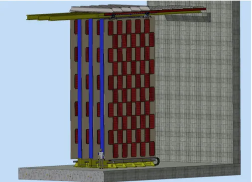
The active layers are composed of individual modules for easier construction and main-tenance, placed on a mechanical support structure. Each module will be enclosed in a case for electromagnetic and light insulation. The modules placement is shown in Fig. 3.3, they are disposed in a checkered pattern on both sides of the supporting structure, staggered to cover the whole layer area. This pattern allows both to reduce the dead area between modules and an even weight distribution on the support structure.
The active layers are installed on sliding tracks to allow for an easier access to modules in case of maintenance. Fig. 3.4 shows muon detector with its layers pulled out on the side.
Figure 3.3: Modules placement on the active layer support structure. On the backside their pattern is identical but staggered.
3.3.1
Tiles
Tiles are the basic building block of the active layer. They are made of plastic scintil-lator directly coupled with silicon photomultipliers. Blue sensitive SiPMs are employed in order to match the scintillating light spectrum of the chosen scintillator. Tiles will be made light-tight by either a aluminized mylar wrapping or a titanium dioxide paint coating, that will enhance scintillation light collection as well.
The intrinsic time resolution of scintillators, SiPMs and electronics can reach well below 100 ps, and in our case the limit is given by the uncertainty in the hit position and sub-sequent light propagation delay spread. The feasibility of a detector based on tiles has been demonstrated with preliminary tests on 6 ˆ 6 cm2tiles [16], that showed that a time resolution of „ 260 ps can easily be achieved for that size. Through the optimization of the SiPM type and placement along the tile, as well as coating type, we aim at achieving ă 400 ps on a tile with an area of about 200 cm2. In this way the detector, with a high-quality global timing distribution, can reach a ă 200 ps time resolution combining four layers.
Figure 3.4: Displaced active layers for easier access during maintenance.
Various configurations have been proposed, with optimizations of both time resolution and cost effectiveness, considering the production size for the detector. At the moment, two main configurations are under investigation.
Rectangular Tile
The first design has been developed by the INFN Laboratories of Frascati. It consists of a rectangular tile with dimensions of 10 ˆ 20 cm. The tile is read out by six SiPMs, symmetrically placed on the longer sides, three per side. These SiPMs have a sensitive area of 4 ˆ 4 mm2 and are produced by Hamamatsu. The MUSIC [18], an 8-channel inte-grated circuit specifically developed for SiPM readout, provides amplification the SiPM signals and their analog sum.
This tile can reach a time resolution of about „ 320 ps, meeting the intended ob-jective. However, some characteristics of this tile configuration can be improved: for
Figure 3.5: Rectangular tile, with six SiPMs read-out and ASIC digitizer board.
example, the electronic readout, while having shown a good overall perfomance during tests, may be too expensive for employment in a large area detector. Moreover, this tile has some ”blind” spots: in the corners the light signal cannot be seen very well by the closest SiPM due to refraction effects, and thus the signal is slower as photons have to reach a SiPM on the opposite side. A narrow spread in propagation delay is crucial to obtain a good time resolution, and these effect can be attenuated with a different placement of the SiPMS, like the one illustrated in the next paragraph.
Square Tile
A square tile was proposed to improve on the rectangular tile design. The tile area is 15 ˆ 15 cm2, slightly larger than the rectangular one, and is read out by four SiPMs instead of six [16]. This allows to reduce the number of required components, further reducing costs. In this case blue-sensitive SiPMs are employed as well, and several models are currently under evaluation. The SiPMs are placed on the tile corners, which are beveled at 45 degrees, as shown in Fig. 3.6. This configuration allows to mitigate the blind areas that the rectangular tile had, and have a more homogeneous time response.
The readout circuit for amplification and analog sum of the SiPMs output is based on discrete components and has been designed specifically for this tile configuration. A detailed description of the latter, and of the tile components working principles as well, can be found in next chapter. This read out solution is convenient because it allows to mount the amplifier very close to the SiPM, minimizing the electronic noise and cabling costs.
This thesis focuses on the development and optimization of this tile configuration, carried out by the INFN section of Bologna. In the next chapters, the details of the tested prototypes with different configurations will be shown, as well as the measurements carried out to evaluate their performance.
Figure 3.6: Square tile with simplified diagram of readout electronics.
3.3.2
Detector Module
For an easier assembly of the full detector, 32 tiles will be preassembled in a module to-gether with a digitizer board. This configuration minimizes the length of analog cabling as well.
The actual tiles arrangement is currently under evaluation, with two possible configura-tions. These designs employ the square tiles as baseline technology: the first one exhibits tiles placed next to each other, as shown on the left side of Fig.3.7, leaving a small per-centage (ă 0.5%) of dead area due to the tile beveled corners. This configuration allows an easy mechanical assembly.
In other one instead, on the right side of Fig.3.7, the tiles are overlapped for 1 cm in the y direction. This configuration requires a more complicated design for a supporting structure, but reduces effectively the dead area. Digitization of the signal is foreseen to be done by the SAMPIC WaveformTDC [19] (Fig. 3.8), a 16 channel switched capacitor digitizer. This device records pulses in a fast analog memory with a 64 cell depth, at 11 bit vertical resolution. Each channel also integrates a discriminator that can trigger itself independently or participate to a more complex trigger. After triggering, analog data is digitized by a on-chip Analog to Digital Converter (ADC) and is sent serially to the DAQ. Offline interpolation allows for better than 10 ps resolution on threshold crossing time.
The SAMPIC has a relatively large dead time (1 µs), but this does not represent a limitation, given the low expected occupancy per channel in the muon detector. Two
Figure 3.7: Module mechanical designs. On the left, tiles are placed next to each other, on the right, tiles are slightly overlapped in the y direction in order to reduce dead areas.
Figure 3.8: SAMPIC WaveformTDC.
SAMPICs can be mounted in one digitizer board, together with a small FPGA, to instrument one module of the detector. Fig. 3.9 show a conceptual scheme of the digitizer board, in a simplified case with eight tiles. Groups of four or eight tiles share the low voltage and bias channels to reduce the number of components. Moreover, the board is equipped with sensors for monitoring environmental and component temperature.
Scintillation detectors
In this chapter the working principles of a scintillator detector equipped with Silicon Photomultipliers are presented.
4.1
Scintillators
When a charged particle traverses matter, it excites molecules along its path. When they return to the ground states, certain types of molecules release a small fraction of this energy as photons of the visible or near to visible light spectrum. This process is known as scintillation, and a material in which the conversion of excitation energy into light is highly efficient is called scintillator.
While many scintillating materials exist, not all are suitable as detectors. In general, a good detector scintillator should satisfy the following requirements [20]:
• high efficiency of light production; • short decay constant (fast signal);
• transparency to its own scintillation light;
• emission spectrum overlapping with the spectral response of photon detectors. No material simultaneously meets all criteria, and the choice of scintillator is often a compromise among these factors. Scintillators are broadly divided into organic and inor-ganic scintillators. Their characteristics will be explained in detail in the next sections, focusing in particular on organic scintillators.
Figure 4.1: A plastic scintillator illuminated by UV light.
4.1.1
Inorganic Scintillators
Most of the inorganic scintillator materials, known as phosphors, are salt crystals, often activated with dopants. The most common types are alkali halides, activated by heavy metals such as thallium, and zinc sulphide, activated by copper, silver or manganese. Inorganic scintillators depend primarily on the crystalline energy band structure of the material for the scintillation mechanism [21]. Figure 4.2 shows an energy band diagram for a typical inorganic scintillator. If a charged particle interacts in the scintillation material, it can excite numerous electrons from the valence and lower-bound bands up into the conduction bands.
These electrons rapidly lose energy and fall to the conduction band edge EC. As they de-excite and drop back into the valence band, they can lose energy through light emissions. If the radiated energy is equivalent to Eg, the radiated photons can be re-absorbed, and the scintillator is essentially opaque to its own emissions. An impurity added to the crystal can introduce allowed states in the band gap (depicted in Fig. 4.2b), called activated scintillator. The excitation process remains similar to that of the intrin-sic case. However, a significant fraction of electrons can fall into the activator excited state. Transitions to the activator ground state release sub-band-gap photon energies and avoid reabsorption. There are exceptions in which intrinsic scintillators work well without activators; examples are bismuth germanate (Bi4Ge3O12 or BGO) and barium fluoride (BaF2).
Figure 4.2: Two basic methods by which an inorganic scintillator produces light: (a) the intrinsic case and (b) the extrinsic case, in which an activation material is added to the scintillator. [21]
4.1.2
Organic Scintillators
The organic scintillators are aromatic hydrocarbon compounds containing linked or con-densed benzene-ring structures. Organic scintillators use the ionization produced by charged particles to generate optical photons, usually in the blue to green wavelength region. Their most distinguishing feature is a very rapid decay time of the order of a few nanoseconds or less.
Scintillation Mechanisms
Scintillation light in organic compounds arises from transitions made by the free valance electrons of the molecules [22]. These delocalized electrons are not associated with any
particular atom in the molecule, and occupy the π-molecular orbitals. Energy deposition from a charged particle passing through the material excites the electrons from the ground state to higher-energy excited states.
The excess energy can be dissipated in various ways. The energy of incident radiation is transferred to particular atoms, causing an electron transition from the basic S0 state to the excited state S1 or higher, depending on the energy. Non-radiative transitions occur quickly between vibrational sub-states of S1 (dashed arrows in Fig. 4.3) to the S1 basic state.
Then, there is an electron transition from S1 to S0 state. The excess of the energy is radiated as fluorescence photons within UV or visible wavelengths.
For scintillation detectors, the transition from S1 vibrational states to S1 base level is favorable. In such decay electrons lose a part of their energy and, as a consequence, the absorption and emission spectra of scintillating materials are shifted as a function of light wavelength. In this way, the absorption and emission spectra of such materials do not match, hence disfavoring the re-absorption of the scintillation light in the material. The above mentioned S-band transitions are not the only transitions possible in organic scintillators. Another mode of electron relaxation is through the vibrational levels in the triplet T0 band. The process is graphically depicted in on the right side of Fig. 4.3.
Figure 4.3: Scheme of the singlet and triplet energy level diagram of organic scintillators.
As before, the incident radiation transfers the electrons from the S0 ground level to the S1 vibrational levels. These electrons first decay into the S1 ground level through radiationless transitions. Now, instead of falling into the S0 level directly, the electrons
can also first go to the available T0 levels. These triplet levels are much more stable than the singlet levels, and consequently the electrons can be thought of being trapped there for an extended time. From the T0 ground level, into which all electrons eventu-ally decay, they fall into the S0 levels. This also results in the emission of light, but in this case it is called phosphorescence or delayed fluorescence since it is emitted after a substantial delay, which is more than 100 ns for typical organic scintillators.
4.1.3
Plastic scintillators
If an organic scintillator is dissolved in a solvent that can be then be subsequently poly-merized, the equivalent of a solid solution can be produced. A common example is a solvent consisting of styrene monomer in which an appropriate organic scintillator is dis-solved. The styrene is then polymerized to form a solid plastic. Other plastic matrices can consist of polyvinyltoluene or polymethylmethacrylate. Because of the ease with which they can be shaped and fabricated, plastics have become an extremely useful form of organic scintillator.
Typical plastic scintillators are ternary systems, consisting of three components: poly-meric base, primary fluor and secondary fluor, so-called wavelength shifter (WLS). A scheme of energy transfer in plastic scintillator is shown in Fig. 4.4.
Figure 4.4: Block scheme of energy transfer in plastic scintillators.
Three components of the plastic scintillators are shown in Fig. 4.4 in particular a se-quence, however the scintillator is a homogeneous mixture of these chemical compounds. The incident radiation interacts with polymer molecules exciting them. The energy is transferred in a non-radiative way to the primary fluor through the F¨orster mechanism
![Figure 2.1: Overview of the SHiP experiment. [12]](https://thumb-eu.123doks.com/thumbv2/123dokorg/7395265.97398/21.918.142.755.675.881/figure-overview-of-the-ship-experiment.webp)
![Figure 3.1: Preliminary simulation of hit rate in the muon detector, here segmented in 10 ˆ 20 cm tiles.[16]](https://thumb-eu.123doks.com/thumbv2/123dokorg/7395265.97398/34.918.243.712.394.666/figure-preliminary-simulation-rate-muon-detector-segmented-tiles.webp)