Politecnico di Milano
V Facolta di Ingegneria
Corso di Laurea Specialistica in Ingegneria delle
Telecomunicazioni
AN ALGORITHM FOR DETECTION AND
MITIGATION OF DEGRADATION ATTACK IN
ETHERNET PASSIVE OPTICAL NETWORKS
Relatore: Prof. Giacomo Verticale
Correlatore: Dr. Massimo Tornatore
Tesi di Laurea di: Sanda Drakulić
“I’m great believer in luck, and I find the harder I work the
more I have of it.”
Table of contents
Introduction
1
Chapter 1. Ethernet Passive Optical Networks (EPONs)
2
1.1 Basic components of EPON 3
1.2 Near-Far problem 4
1.3 Spectrum sharing vs. time sharing 5
1.4 Multi-Point Control Protocol (MPCP) 7
Chapter 2. TDMA EPON security issues
8
2.1 Eavesdropping 8
2.2 Denial of Service (DoS) 9
2.3 Degradation attack 10
2.3.1 TCP – congestion control algorithms 10
2.3.2 Degradation attack scenario 13
Chapter 3. Evaluation of existing fault detection and
17
authentication techniques
3.1 Detection methods 17
3.1.1 Power detection method 17
3.1.2 Pilot tones 18
3.2 Authentication techniques 19
3.2.1 Method 1 – Authentication technique 19 using loopback modulation
3.2.2 Method 2 – Authentication technique 21 using periodic probing signal
Chapter 4. Implementation of degradation attack
24
in OMNeT++
4.1 OMNeT++ 24
4.1.1 Basic methods, functions and classes 25
4.2 Simulation model of EPON 28
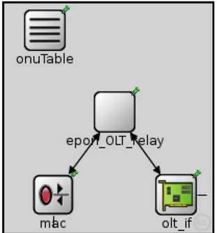
4.2.1 OLT 28
4.2.2 ONU 31
4.2.3 PON Splitter 31
Chapter 5. Algorithm for mitigation of degradation attack 32
5.1 Degradation attack 32
5.1.1 TCP transmission server-to-client 33 5.1.2 TCP transmission client-to-server 36
5.2 Detection and mitigation of degradation attack 38
5.2.1 Detection algorithm 38
5.2.2 Mitigation algorithm 41
Chapter 6. Analysis of simulation results
44
6.1 TCP transmission client-to-server 44
6.2 TCP transmission server-to-client 49
6.3 Interaction of retransmission time-out mechanism 53 and mitigation algorithm
Chapter
7.
Conclusion
57
Bibliography
58
Abstract
The work presented in this thesis is based on adding new techniques to enhance current security in Ethernet Optical Passive Networks (EPONs). An Ethernet PON is type of Passive Optical Network (PON) which carries all data encapsulated in Ethernet frames. In this way EPON combines Passive Optical Networks (PONs) capable of delivering bandwidth-intensive integrated, data, voice, and video services at distances beyond 20 km with Ethernet protocol. Main advantage of Ethernet protocol is that it is an inexpensive technology that is ubiquitous and interoperable with variety of legacy equipment. Due to exponential growth of internet traffic in the last decades and high number of new services and applications which require large bandwidth existing technologies based on cooper (e.g. Digital Subscriber Line(DSL)) could not keep any more with such demands. EPON has emerged to be good candidate for offering higher capacity to the subscribers under relatively low costs. As in every telecommunication network that is serving high number of users transferring data at the high bit rate, security in EPON is one of very important issues.
While security in downstream transmission channel in EPON was focus of many researches due to its broadcast nature, upstream direction was always assumed to be secure. In upstream direction, due to directional properties of passive couplers, which act as passive splitters for downstream, Ethernet frames from many ONU will only reach the OLT and not any other ONU. In this scenario attacks like eavesdropping and all other attacks that are based on exploiting broadcast nature of transmission channel are eliminated. But this does not means that upstream streams cannot be destroyed or that quality of upstream transmission cannot be degraded in some way. In upstream direction, the logical behavior of an EPON is similar to point-to-point networks, but unlike in a true point-to-point network, collisions may occur among frames transmitted from different ONUs. In general EPON should avoid collisions by means of Multi-Point Control Protocol (MPCP) in the Medium Access Control (MAC) layer. But eventual collisions in upstream direction can not be totally excluded.
In fact we will show that if some ONUs do not comply with the directives issued by the MPCP protocol collisions can happen in upstream direction despite to working scheme of MPCP. More precisely we will describe attack that exploits fact that ONUs can send frames even out of its assigned time slots and as final result gain more bandwidth causing collisions in data transmission of other well behaved ONUs (the ones that are sending data only within assigned time period). ONUs that are not respecting their time-slot allocation will be called from now on malicious ONUs.
Based on simulations ran in open source simulator OMNeT++ we will show that indeed that this kind of behavior will bring malicious ONU extra bandwidth while other ONUs will experience lack of capacity.
We will conduct experiments on two types of TCP transmissions, referred to as client-to-server and client-to-server-to-client. In case of client-to-client-to-server ONUs are the ones that are sending data while TCP server are sending messages acknowledging that they have successfully received messages from ONUs. In other case it is the other way around, servers are the ones that are sending data while ONUs are sending ACK messages.
Based on upper introduced types of TCP transmission we will show that in case of server-to-client transmission malicious ONU will gain extra bandwidth while in case of client-to-server malicious will not gain any extra bandwidth for itself but it will decrease upstream throughput of other ONUs in the network. This is consequence of static bandwidth allocation that was used in all of our simulations.
Secondly, we will show one of possible techniques that can be applied in this kind of attacks in order to detect malicious ONU and then in some way punish it for acting in this way. Proposed algorithm has two phases: detection of malicious ONU and mitigation phase. In case of detection phase first we showed currently exiting detection methods in case of faulty terminal and explained why they are not suitable for detection of malicious ONU in case of degradation attack. Then we have explained working principles of our detection technique and explained why it is working better in case of degradation attack than previous ones. Second phase is based on mitigating effects of degradation attack. During this phase we will start delaying packets originating from malicious ONU. Based on simulation results we will show how different delays have different effects on throughput of malicious ONU. More precisely we will show that in order to halve the throughput our mitigation technique has to introduce delay that is equal to 30 polling cycles or more. Unfortunately we cannot repair the damage inflicted on the well behaved stations by malicious ONU. Throughput of well behaved ONU will keep decreasing but the gap between throughput of ONUs respecting their time slot allocation and malicious ONU will downsize.
Sommario
Il lavoro presentato in questa tesi propone una nuova tecnica per migliorare la sicurezza delle Ethernet Optical Passive Networks (EPONs). Una PON Ethernet è una tipologia di rete ottica passiva (Passive Optical Network) che trasporta dati incapsulati all'interno di trame Ethernet. In questo modo essa combina la capacità propria delle PONs di trasportare servizi dati, voce, video ed integrati a larga banda per distanze superiori ai 20km con le caratteristiche del protocollo Ethernet. Tale protocollo si configura come una tecnologia a basso costo, caratterizzata da ampia diffusione ed interoperabilità con i dispositivi standard di rete. La crescita esponenziale del traffico Internet verificatasi durante l'ultimo decennio ha favorito la diffusione di innumerevoli servizi ed applicazioni a larga banda, i quali comportano una richiesta di risorse che le tecnologie esistenti (ad esempio le Digital Subscriber Lines(DSL) con doppino in rame) non sono più in grado di soddisfare. Le reti EPON hanno dimostrato di essere potenziali candidate per offrire agli utenti maggiore capacità, a costi relativamente contenuti. Naturalmente, come in ogni rete di telecomunicazioni adibita a servire un alto numero di utenti trasferendo dati ad alto bit-rate, anche nelle EPON la sicurezza di rete costituisce un aspetto fondamentale.
Innumerevoli attività di ricerca sono state finalizzate a garantire la sicurezza del canale di trasmissione in downstream delle EPON, a causa della sua natura intrinsecamente broadcast, mentre la direzione upstream è stata sempre assunta come sicura. Infatti, grazie alle proprietà direzionali degli accoppiatori, che si comportano da splitter passivi in downstream, le trame Ethernet generate da ciascuna ONU raggiungono soltanto l'OLT e non le altre ONU. In uno scenario di questo tipo, attacchi basati sullo sfruttamento del broadcasting del canale di trasmissione sono dunque eliminati. Tuttavia, ciò non implica che non possano verificarsi collisioni in upstream, o che la qualità delle trasmissioni upstream non possa essere degradata: in tale direzione infatti, il comportamento logico di una EPON è simile a quello delle reti point-to-point ma, a differenza di queste ultime, possono verificarsi collisioni tra trame trasmesse da ONU differenti. In genere le EPON eliminano le collisioni grazie al Multi-Point Control Protocol (MPCP) a livello Medium Acces Control (MAC), che tuttavia non fornisce garanzie di sicurezza assolute.
In primo luogo, in questa tesi verrà infatti mostrato che se alcune ONU non obbediscono agli standard imposti dal protocollo MPCP, possono comunque verificarsi collisioni nella direzione upstream. Più precisamente, verranno descritti gli attacchi basati sulla possibilità delle ONU di inviare trame anche al di fuori del time slot ad esse assegnato, al fine di ottenere maggiore banda. Tali ONU, che verranno d'ora in avanti definite maligne giacchè il loro comportamento intrusivo inficia le prestazioni della rete, causano collisioni con le trasmissioni delle ONU che inviano dati soltanto durante il proprio time-slot.
Sulla base di simulazioni condotte tramite il simulatore open source OMNeT++ verrà quindi provato che questo tipo di comportamento comporta effettivamente un guadagno di banda per la ONU maligna, mentre le altre ONU sperimenteranno una diminuzione della capacità loro assegnata. Sono stati considerati due tipi di trasmissioni TCP, indicate come client-to-server e server-to-client. Nel primo caso, le ONU inviano dati mentre i server TCP inviano messaggi di riscontro che segnalano la corretta ricezione. Nel secondo caso invece i ruoli si invertono: i server inviano dati e le ONU li riscontrano con messaggi di ACK.
Per questo tipo di scenario si mostrerà che, in caso di trasmissioni server-to-client, la ONU maligna guadagna banda aggiuntiva, mentre nel caso client-to-server ciò non si verifica ma l'attività della ONU maligna causa un decremento del throughput upstream delle altre ONU della rete. Questi risultati sono diretta conseguenza dell'allocazione statica di banda che ha costituito l'assunzione di base per le simulazioni effettuate.
In secondo luogo, verrà proposta una possibile tecnica da applicare in condizioni di attacco per individuare la ONU maligna e per punire il suo comportamento intrusivo. L'algoritmo implementato consta di due fasi: l'individuazione della ONU maligna e la mitigazione della sua attività. Per quanto riguarda la fase di identificazione, verranno descritti i metodi attualmente utilizzati, evidenziando i motivi per cui essi si rivelano inadatti a determinare quale sia la ONU maligna in caso di attacchi di degradazione. Verranno poi illustrati i principi di funzionamento della tecnica di identificazione proposta, sottolineando gli aspetti che la rendono più efficiente delle precedenti.
La fase di mitigazione prevede invece che, una volta individuata la ONU maligna, i pacchetti da essa generati vengano ritardati. Sulla base dei risultati sperimentali verrà evidenziato l'impatto che differenti ritardi hanno sul throughput della ONU maligna. In particolare, verrà mostrato che per dimezzare il throughput è necessario introdurre un ritardo pari o maggiore di 30 cicli di polling. Purtroppo non è possibile compensare il danno inflitto alle ONU benigne: il loro throughput continuerà a decrescere, ma verrà ridotta la differenza rispetto a quello della ONU maligna.
Introduction
The tremendous growth of Internet traffic in the last decades has accentuated the aggravating lag of access network capacity. The so-called “last mile” problem still remains the bottleneck between high capacity Local Area Networks (LANs) and the backbone network Most of current implementations of “last mile” are cooper-based and they are unable to provide enough bandwidth to current high-speed Gigabit Ethernet local area networks and evolving services. A new technology is required; one that is inexpensive, simple, scalable and capable of delivering bundled voice, data, and video services over a single network.[1]
In so-called FTTx access networks the cooper based distribution part of access networks is replaced with optical fiber, e.g. fiber to the curb (FTTC) or home (FTTH). In doing so, the capacity of access networks is sufficiently increased to provide broadband services to subscribers. Due to the cost sensitivity of access networks these all-optical FTTx systems employ a passive ( not requiring any power) device to split optical signal from one fiber into several fibers and reciprocally, to combine optical from multiple fibers to one. Accordingly, they are called Passive Optical Networks (PONs).
Passive optical network is a technology viewed by many as an attractive solution to the last mile problem since:
• PONs allow for long reach between central offices and customer premises, operating at distances over 20 km.
• PONs minimizes fiber deployment in both local exchange office and the local loop. • PONs provides higher bandwidth due to deeper fiber penetration offering gigabit
per second solutions or even more.
• Being optically transparent end to end, PONs allows upgrades to higher bit rates or additional wavelengths.
In the beginning PON was defined with Asynchronous Transfer Mode (ATM) as its native Protocol Data Unit (PDU) since ATM had big hopes of becoming a prevalent technology in LAN, MAN and backbone. However, since that time other layer-2 protocol has leapfrogged ATM- Ethernet. Because of quite expensive equipment, wasted bandwidth and processing resources due to retransmission policy ATM has lost the battle against Ethernet. Furthermore, given the fact that more than 90 % of today’s traffic originates from and terminates in Ethernet LANs, Ethernet based PONs appear to be a natural candidate for future last mile solutions [2].
In every network architecture, special attention was always given to security issues. Security requirements in EPON are based on the fact that EPON serves non cooperative, private users, but also has a broadcasting downstream channel, potentially available to any interested party capable of operating an end station in promiscuous mode.
In fact downstream channel is inherently “prone” to eavesdrop. Eavesdropping is possible by operating an ONU in promiscuous mode: being exposed to all downstream traffic, such an ONU can listen to traffic intended to other ONUs. Point-to-point emulation adds Logical Link IDs (LLIDs) that allow an ONU to recognize frames intended for it and to filter out the rest. However, this mechanism does not offer the required security, as an ONU might disable this filtering and monitor all traffic. There are also many other attack that arise based upon eavesdropping. For example we can mention Theft of service (ToS).
ToS occurs when a subscriber impersonates a neighbor and transmits frames that are not billed to the impersonator’s account. To be able to transmit in hijacked timeslot, the impersonating ONU must eavesdrop on the downstream to receive GATE messages addressed to a victim. In order to enhance downstream transmission encryption is introduced. Encryption techniques based on not shared key provide privacy for subscriber data and make impersonation of another ONU difficult. Thus, a point-to-point tunnel is created that allows private communication between OLT and different ONUs. In general, security of downstream channels is based on encryption. On the other hand upstream channel was assumed to be relatively safe. Due to directivity of a passive combiner, the upstream traffic is visible only to the OLT. In this scenario attack based on eavesdropping are eliminated.
In this work we will show that also in upstream direction there are weak spots that malicious user can exploit to implement very intrusive attack called, degradation attack. These kinds of attacks are based on destroying upstream transmissions of other ONUs in the network by introducing disturbing signal. Malicious ONU that is performing degradation attack will send data out of its assigned time slot and in this way gain more bandwidth in detriment of other ONUs. Sent packets will cause upstream collisions that will have deep influence on behavior of upper layer protocols, more precisely on TCP protocol. Detected collisions will be interpreted by TCP as a sign of congestion occurrence in the network and according to TCP working scheme it will invoke appropriate congestion avoidance procedures in order to decrease transmission rate and in this way solve the problem of congestion.
This thesis is divided into seven chapters:
• Chapter 1 provides an overview of EPON architecture.
• In chapter 2 we will highlight security problems present in this kind of networks focusing on degradation attack.
• Chapter 3 is based on presenting main techniques fro detection and authentication of faulty terminals. Also in this chapter it will be discussed why this techniques are not suitable for coping with degradation attack.
• In chapter 4 we will explain basic classes and functions in OMNeT++ used for our simulations. Then general architecture of EPON in OMNeT++ simulator will be described also.
• In chapter 5 we will explain working principle of degradation attack fro both TCP transmission client-to-server and server-to-client and show new technique to detect malicious ONU in case of degradation attack and mitigation technique used in order to punish ill behaved ONU.
• In chapter 6 we will discuss obtained results in OMNeT++. • Chapter 7 is dedicated to conclusion of this thesis.
Chapter 1. Ethernet Passive Optical Networks (EPONs)
EPONs represent the convergence of low-cost and widely used Ethernet equipment and low-cost point-to-multipoint fiber infrastructure and in this way they seem to be the best candidate for the next-generation access network as it was mentioned in introduction. In the following subchapters, EPON architecture and working principle will be described.
1.1 Basic components of EPON
An EPON consists of a central office node, called an Optical Line Terminal (OLT), one or more user nodes, called Optical Network Units (ONUs) and the fibers and splitters between them, called the Optical Distribution Network (ODN) as shown on figure 1. The OLT provides the interface between the EPON and the service providers network services. On the other hand ONU terminates the EPON and presents the native service interfaces to the user [3].
Figure 1. EPON architecture
The Passive Optical Splitter (POS) connects OLT and ONU, functioning to distribute the downlink data and aggregate the uplink data. In EPON, the single-core optical fiber is used to transmit uplink and downlink wavelengths.
In the downlink direction the OLT in the central office broadcasts the data, voice and video services to all ONUs in the EPON using the 1:N POS of the ODN, in the uplink direction, the services from different ONUs are coupled into a fiber without interference via the 1:N POS of the ODN and ultimately sent to the OLT receiver of the local exchange.
1.2 Near-Far problem
Due to possibly unequal distances between ONUs within EPON, optical signal attenuation may not be the same for each ONU within EPON. The power level received may be different for each time-slot. This problem is known as near-far problem. If the receiver in the OLT is adjusted to properly receive a high power signal from close ONU, it may mistakenly read 1s as 0s when receiving a weak signal form distant ONU. In the opposite case, if the receiver is trained on a weak signal, it may read 0s as 1s when receiving a strong signal. To detect the incoming bit stream properly, the OLT receiver must adjust its 0-1 threshold at the beginning of each received burst, a procedure known as automatic gain control (AGC). The mode of operation in which signal arrives at the receiver in the bursts with varying power levels is called burst-mode reception.
Some architectures attempt to reduce the necessary dynamic range of the AGC circuitry by forcing the ONUs to adjust their transmitter powers, such that power levels received by the OLT from all the ONUs become nearly equal. This method is not particularly favored by equipment designers, as it makes the ONU hardware more complicated, requires special signaling protocol for feedback from the OLT to each ONU and most importantly, may degrade performance of all ONUs to that of a most distant unit. In addition to performing AGC, burst-mode receivers must be able to acquire phase and frequency lock on an incoming signal. This procedure is called clock and data recovery (CDR). The ability to perform AGC and CDR very quickly is paramount for a receiver to operate in burst mode. A burst mode receiver is necessary only in the OLT. The ONUs receive a continuous bit stream (data or idles) sent by OLT and do not need to readjust the receiver gain quickly. In a TDMA EPON (as it will be explained in the next section we are taking in consideration TDMA based EPON) it is not enough just to disallow ONUs from sending any data between the assigned timeslots. The problem is that, even in the absence of data, lasers generate spontaneous emission noise. Spontaneous emission noise from several ONUs located close to the OLT can easily obscure the signal from a distant ONU (capture effect).
To avoid the capture effect, ONUs must shut down their lasers between timeslots. The mode of operation in which the laser is being completely turned off between the transmissions is called burst-mode transmission. Because a laser cools down when it is turned off, and warms up when it is turned on, its emitted power may fluctuate at the beginning of transmission. In burst mode transmitters, it is important that the laser be able to stabilize quickly after being turned on.
1.3 Spectrum sharing vs. Timesharing
In the downstream direction (from OLT to ONUs), an EPON is point-to-multipoint (P2MP) network. The OLT typically has entire downstream bandwidth available to it at all times. In the upstream direction, an EPON is multipoint-to-point network (MP2P): multiple ONUs transmit all towards one OLT. Directional properties of POS are such that the transmission of an ONU cannot be detected by other ONUs. However, data streams from different ONUs transmitted simultaneously still may collide. Thus in the upstream direction (from user to network i.e. from ONU to OLT), EPON should employ some channel separation mechanism to avoid data collisions and fairly share the trunk fiber capacity and resources.
One possible way of separating the upstream channels of different ONUs is to use Wavelength Division Multiple Access (WDMA), in which each ONU operates on different wavelength. While it is a simple solution (from a theoretical perspective), it remains cost-prohibitive for an access network. A WDMA solution would require either a tunable receiver, or receiver array at the OLT to receive multiple channels. An even more serious problem for network operators would be wavelength specific inventory; instead of having just one type of ONU, there would be multiple types of ONUs based on their laser wavelengths. Each ONU will have to use a laser with narrow spectral width and thus will become more expensive. Using tunable lasers in ONUs may solve the inventory problem, but it is too expensive at the current state of technology. For these reasons, a WDMA EPON is not an attractive solution in today’s environment.
If a single tunable receiver is used at the OLT, then a data stream from only one ONU can be received at a time, which in effect makes it Time Division Multiple Access (TDMA) EPON. In a TDMA EPON, simultaneous transmissions from several ONUs will not collide when reaching the combiner. In order to prevent data collisions, each ONU must transmit in its own transmission window (timeslot) i.e. all ONUs are synchronized to a common time reference and each ONU is allocated a time slot. An ONU should buffer frames received from subscriber until its time slot arrives.
One of the major advantages of TDMA EPON is that all ONUs can operate on the same wavelength and be absolutely identical. The OLT will also need a single receiver. A transceiver in ONU must operate at the full line rate, even though bandwidth available to the ONU is lower. However, this property also allows TDMA EPON to efficiently change the bandwidth allocated to each ONU by changing the assigned time slot size, or even employing statistical multiplexing to fully utilize the bandwidth available in the EPON. In a subscriber access network, traffic flows downstream and upstream but not peer-to-peer e.g. ONUs cannot communicate directly. Thus it seems reasonable to separate the downstream and the upstream channels. A simple channel separation can be based on Space Division Multiplexing (SDM) where different fibers are used for the downstream and the upstream traffic.
To save optical fiber and reduce cost of repair and maintenance, a single fiber can be used for bi-directional transmission. In this case two wavelengths are used: typically 1330 nm for the upstream transmission and the 1550 for the downstream transmission. The channel capacity on each wavelength can be flexibly divided between the ONUs.
Time-sharing appears to be preferred method for transmission technique within EPONs since it allows a single upstream wavelength, such as 1310 nm, and a single transceiver at OLT, resulting in cost effective solution.
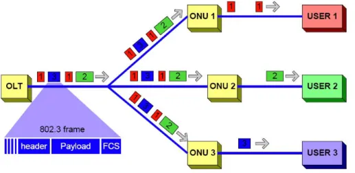
Figure 2. Upstream traffic in TDM EPON.
Figure 3 depicts how packets are sent in upstream direction. Each of ONUs has its assigned time slot within which is allowed to send data. When time assigned for transmission elapses ONU should stop with transmission and buffer all incoming data from user until it is again its turn to start with transmission.
In the downstream direction, Ethernet frames transmitted by OLT pass through 1:N splitter and reach each ONU. N is typically between 4 and 64. Because Ethernet is broadcast by nature, in downstream direction it fits perfectly with Ethernet PON architecture: packets are broadcast by OLT and extracted by their destination ONU based on the Medium Access Control (MAC) address (Figure 3.).
1.4. Multi-Point Control Protocol (MPCP)
The MPCP arbitration mechanism developed by the IEEE 802.3ah Task Force is used to dynamically assign non overlapping upstream transmission windows (time slots) to each ONU. This protocol relies on five messages for control: GATE,REPORT, REGISTER_REQ,REGISTER and REGISTER_ACK.
There are two modes of operation of MPCP:
• auto-discovery (initialization) mode which is used to detect newly connected ONUs and learn the round-trip time (RTT) and MAC address of that ONU, plus maybe some additional parameters yet to be defined.
• bandwidth assignment mode used to assign transmission grants to all initialized ONUs.
In the following text we will describe more in details bandwidth assignment mode since its working principles are important for understanding better next chapters of this thesis. During bandwidth assignment mode a GATE message is sent from the OLT to an individual ONU and is used to assign a transmission timeslot to this ONU. A timeslot is identified by pair of values {startTime, length}.
Based on how time slot are assigned to ONUs we have two different types of bandwidth allocation: static bandwidth allocation (SBA) and dynamic bandwidth allocation (DBA). The static allocation of bandwidth requires that the bandwidth allocation i.e. time-slot assignment is done once, before start of the first transmission of user data. Once set, this bandwidth remains statically assigned and is fully insensitive to the varying bandwidth needs of ONUs. On the other hand dynamic bandwidth allocation is automatically allocated based on demands i.e. bandwidth requirements of different ONUs.
In the ONU, the received GATE message is processed in way to obtain the start and duration of transmission. Additionally, an indication of the received GATE message is passed to the DB agent at the ONU to allow it to perform any necessary DBA-specific function, e.g., select the order of frames to be sent out.
A REPORT message is a feedback mechanism used by an ONU to convey its local conditions (such as buffer occupancy) to the OLT. This type of message is sent only in case of dynamic bandwidth allocation since DBA will then use information from REPORT message in order to make intelligent allocation decisions. In the case of SBA, the OLT generates a GATE message without a REPORT from the ONUs, so it allocates a fixed amount of bandwidth in static manner.
REGISTER_REQ, REGISTER and REGISTER_ACK messages are used for plug-in registration of newly entered ONUs to the EPON network i.e. this messages are used during auto- discovery mode [4].
Chapter 2. TDMA EPON security issues
Security has never been a strong part of Ethernet networks. In peer-to-peer (P2P) full-duplex Ethernet security is not a critical issue because there are only two communicating stations using a private channel. In shared half-duplex Ethernet, security concerns are minimized because users belong to a single administrative domain and are subject to a same set of policies.
P2MP Ethernet, however, has a different set of requirements. EPON has a broadcasting downstream channel and serves noncooperative users. In fact, an EPON cannot be considered a peer-to-peer network in that ONUs cannot communicate directly with each other or even learn of each other’s existence. As for downstream traffic main security issue is eavesdropping i.e. case in which malicious ONU reads downstream traffic that is not designated to it. In the upstream direction ONUs share the upstream channel capacity and network resources.
To efficiently use the upstream bandwidth, the OLT allocates the bandwidth to an ONU dynamically. In the case that the malicious ONU generates large amounts of traffics intentionally, other ONUs could not be allocated the bandwidth. Aim of this attack is fully disable attacked user from receiving any service at all without gaining any extra bandwidth for attacker itself. This kind of attack is called Denial of Service (DoS).
Other type of attack that can be performed in upstream direction is so- called (within this work) degradation attack. In this case malicious ONU transmits disturbing signal during time slot of another ONU. These two signals are then combined within optical splitter and transmitted on the same optical fiber to OLT. Upon receiving mixed signal, OLT cannot distinguish original signal from disturbance signal and as final result we have that received packet is recognized as incorrect one.
Aim of this kind of attack is to reduce transmission rates of well-behaved ONUs and in this way gain more available bandwidth for malicious ONU.
2.1 Eavesdropping
In EPON, eavesdropping is always possible in the downstream direction simply by operating one of the registered ONUs in the so-called promiscuous mode. Since each ONU in the network receives a copy of every single downstream packet transmitted by the OLT (more correctly: broadcast by the OLT, since the downstream channel has P2MP properties), no extensive modifications are required in the ONU hardware to enable its operation in malicious mode. All that a network attacker has to do in this case is simply to disable LLID (Logical Link Identifier) filtering rules and enjoy access to all information transmitted in the downstream direction. What makes the situation worse, in this case, is that the employed eavesdropping method is completely passive, undetectable at the OLT level, and does not trigger any visible side-effects in the network behavior.
Therefore, it might go unnoticed and, what is even worse undisturbed 24 hours per day, seven days per week.
In the upstream channel, subscriber data are more secure since, inherently, the network architecture prevents other subscribers from eavesdropping transmissions from other stations, at the hardware level. As such, the upstream channel is considered secure, as far as passive monitoring is concerned. Only the OLT receives ONU transmissions and is aware of the activity periods of individual ONUs. One possible case of eavesdropping in the upstream direction is under assumption that passive optical splitter might introduce signal reflections sufficient enough to reconstruct upstream transmissions originating from other ONUs in the network. However, it has not been proven practically, until now, that such a mechanism is feasible and the existing signal reflections have sufficient power level to allow extraction of any useful signal [5].
2.2 Denial of service (DoS)
A DoS attack causes loss of standard services observed by all registered and active subscribers and potential loss of network connectivity. Typically, the said attack is carried out by consuming a significant share of the available bandwidth and the network resources in the targeted system, overloading any existing pieces of hardware with strenuous and in the many cases infinite tasks, resulting in denial of service for legitimate subscribers and degradation of QoS (Quality of Service), as observed from a user point of view
A standard DoS attack can be performed in a number of ways, comprising three major types of security branches:
• Consumption of computational resources, such as bandwidth, disk space or CP time.
• Disruption of system sensitive configuration information, such as LLID, MAC addresses etc.
• Disruption of network connectivity at the physical level, for example, by flooding the upstream channel with a strong laser signal, thereby preventing useful transmissions from any legitimate subscriber.
The simplest type of DoS attack which can be executed in PON networks, and more specifically in EPONs, is a simple network connectivity disruption, which in this particular case is limited to turning on a strong laser signal source transmitting in the upstream channel at the proper wavelength, coherent with the selected upstream transmission window (Fig.4).
2.3 Degradation attack
Degradation attack is new type of attack which hits the upstream transmission, exploiting working principles of TCP, the typical upper layer protocol running over the EPON network.
Namely, as we mentioned before, transmissions in upstream direction are based on transmission grants, i.e., time slots which are scheduled by OLT. This means that each ONU should respect its assigned transmission grants and send data only within allowed period. There are no monitoring techniques implemented within EPON that are actually controlling if ONUs are respecting assigned time slots. This fact makes room for degradation attack which is based on violation of assigned time slots.
Attacker that is performing this kind of attack will send packets even out of timeslots that are assigned to him by MPCP protocol. Since he will send data we he should not that means that this data will be sent during some other ONU`s transmission period, and ,as final result, we will have upstream collisions. Upon detecting upstream collision protocol TCP takes place. Collisions will trigger retransmission timeout which will then invoke TCP congestion avoidance procedures that will decrease the throughput of affected ONU`s (except malicious ONU).
In following subchapters we will explain more in details TCP`s congestion avoidance procedures and scenario of degradation attack.
2.3.1 TCP-congestion control algorithms
TCP is one of the most widely used protocols in the transport layer on the Internet and plays one of the main roles in determining overall network performances. The design of TCP is based on handling congestion and network overload and fact that the end stations are responsible for controlling the rate of data flow.
In TCP, there are no explicit signaling mechanisms in the network which tell the end stations how fast to transmit, when to transmit, when to speed up or when to slow down. The TCP software in each of the end stations is responsible for answering these questions from implicit knowledge it obtains from the network or the explicit knowledge it receives from the other TCP hosts.
There are several flavors of TCP like TCP Tahoe, TCP Reno, TCP New Reno etc. but in further text when talking about standard TCP we will imply TCP Reno.
Standard TCP flow control is based on receiving acknowledgement (ACK) from receiver’s side after every successfully received byte stream. ACK message contains ACK number which indicates which data are expected to be received next. Based on received ACK sender knows that sent data was received and which data it has to send in the next transmission. Also for each TCP segment sent the sender expects to receive ACK within some period of time otherwise an error in the form of a timer expiring signals that something is wrong. Whenever TCP transmits a segment the sender starts a timer which keeps the track of how long it takes for an ACK for that segment to return. This timer is known as the retransmission timer. If an ACK is returned before the timer expires, the timer is reset with no consequence. If however an ACK for the segment does not return within the timeout period, the sender would retransmit the segment and double the retransmission time value.
If a TCP data segment is lost in the network, a receiver will never know it was once sent. However, the sender is waiting for an ACK for that segment to return. In one case, if an ACK does not return, the sender’s retransmission timer expires which causes a retransmission of the segment. If however the sender had sent at least one additional segment after the one that was lost and the later segment is received correctly, the receiver does not send an ACK for the later, out of order segment. The receiver cannot acknowledgment out of order data, it must acknowledge the last contiguous byte it has received in the byte stream prior the lost segment. In this case, the receiver will send an ACK indicating the last contiguous byte it has received. If the last contiguous byte was already acknowledged, we call this a duplicate ACK. The reception of duplicate ACKs can implicitly tell the sender that a segment may have been lost or delayed. The sender knows this because the receiver only generates a duplicate ACK when it receives other, out of order segments.
In summary, there are two main events that trigger TCP: timeout and duplicate ACK. TCP congestion control mechanisms that are invoked when duplicate ACK occurs are called Fast Retransmit and Fast Recovery. Since degradation attack causes retransmission timeout we will not discuss further these two algorithms since they are not relevant for in case of degradation attack. Other two algorithms that are connected with timeout of retransmission timer are called Slow Start and Congestion Avoidance and we will explain more in details how they interact.
Slow Start is a mechanism used by the sender to adjust transmission rate in accordance with current network load. When a TCP connection first begins, the Slow Start algorithm initializes a congestion window to one segment, which is the maximum segment size (MMS) initialized by the receiver during the connection establishment phase. When ACKs are returned by the receiver, the congestion window increases by one segment for each ACK returned. To be more precise that means that for each ACK returned TCP will send one segment more in the next transmission which in the end results with exponentially increase of data sent during slow start procedure. Slow start will run till reaching the threshold which is called slow start threshold (ssthresh). In moment when congestion window is larger then ssthresh TCP will start with congestion avoidance. During this period congestion window will be increased by one segment each round trip time (RTT) where RTT is length of time that takes for signal to be sent plus a length of time it takes for acknowledgment of that signal to be received.
During both algorithms the TCP sender can transmit the minimum of the congestion window and the advertised window of the receiver(i.e. the amount of packets that can be handled by a receiver), which is simply called send window.
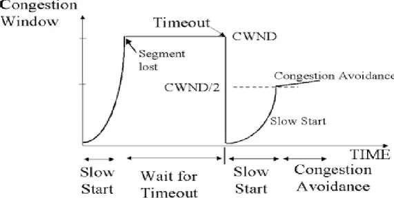
In Congestion Avoidance algorithm a retransmission timer expiring or the reception of duplicate ACKs can implicitly signal the sender that a network congestion situation is occurring. The sender immediately sets the send window to one half of the current window size (the minimum of congestion window and the receiver’s advertised window size). If congestion was indicated by a timeout, the congestion window is reset to one segment, which automatically puts the sender into Slow Start mode (Fig.5.) If congestion was indicated by duplicate ACKs, as it was mentioned the Fast Retransmit and Fat Recovery algorithms are invoked. As data is received during Congestion Avoidance, the congestion window is increased. However Slow Start is only used up to the halfway point where congestion originally occurred. After this halfway point, the congestion window is increased by one segment for all segments in the transmission window that are acknowledged.
This mechanism will force the sender to more slowly increase its transmission rate, as it will approach the point where congestion had previously been detected.
Figure 5. Slow Start and Congestion Avoidance working scheme.
We can conclude in the end that TCP tends to reduce transmission rate i.e. throughput in the case of the congestion detection. This reduction is more aggressive in case of timeout of the retransmission timer since window size is reduced by half and further increasing of the transmission window is exponential (using Slow Start) only till the point where congestion previously had occurred. Further increasing of the transmission window is linear since transmission window is increased only by one segment after every successful transmission. Other important fact about throughput in TCP environment is following equation:
Throughput
=2
RTT
8
3
MSS
cycle
the
of
duration
cycle
one
in
mitted
data trans
2W
W
=
⋅
⋅
⋅
where MSS is maximum segment size i.e. the largest amount of data, specified in bytes, that TCP receiver can receive in single, unfragmented piece.
Taking in consideration that maximum size of congestion window in the moment when congestion had occurred is W and that value of W is computed based on following equation: W= 3⋅8p where p is loss probability, upper throughput equation can be modified as following:
Throughput=MSSRTT Cp
In following paragraph it will be explained why this equation is crucial for analyzing the conducting of a service disruption attack.
2.3.2 Degradation attack scenario
In a TDM EPON all ONUs are synchronized to a common time reference and are allowed to transmit only inside a time window dynamically assigned by the OLT as it was mentioned before. The ONU buffers the frames received from the subscriber network and transmits them at wire speed when the assigned transmission window begins. In this scenario, we define a malicious ONU as a station capable of transmitting outside its assigned window. In order to behave as malicious ONU, attacker has to be capable of tuning the ONU`s laser in such way that ONU is also transmitting when it should not have. Control of the physical devices has to be gained by the malicious ONU owner.*
Packets transmitted by malicious ONU do not have to be complete frames and, more likely, are a sequence of random symbols of a given length. These sequences have a chance of colliding at the OLT receiver with a legitimate frame transmitted by a well-behaving ONU.
Two main indicators that collision had occurred are Packet Error Rate (PER) and Frame Error Rate (FER). PER represents ratio of incorrectly receive data packets and total number of transferred packets and it is defined on TCP layer since we are talking about packet structure. On the other hand BER represents ratio of frames received with error and total number of frames sent. Since in this case we are referring to frames, BEr is defined on Ethernet level.
In case of TCP transmission client-to-server legitimate frames will be destroyed by attacker resulting in an increased FER but also in increased PER since lost of frame ia actually also lost of the packet. Packet (frame) loss will be then interpreted by TCP as a signal of congestion, resulting in the congestion avoidance procedures reducing the transmission rate of the source. On the other hand in case of TCP transmission server-to-client we can have high FER while value of PER can be equal to zero due to cumulative ACK that will be explained soon. Shortly, killing couple of ACK messages will increase value of FER since acknowledge message encapsulated in frames will be destroyed but this will not be enough to prevent TCP receiver to acknowledge all received packets so obtained PER will be equal zero.
* In order to ensure high utilization, the upstream transmission of an ONU follows immediately after the upstream transmission of the preceding ONU. Two transmissions are separated by guard period which at maximum, based on 802.3ah recommendations, can be 800ns. This gain is used for measuring power level of received signal and adjusting gain level at OLT side properly. Having only guard period within which no data is transmitted tells us that sending data out of its assigned time slot malicious ONU will surely fall into transmission period of some of well behaved ONUs
At steady state, the throughput of a TCP flow is showed to be inversely proportional to the square root of the packet loss probability along the bidirectional path. Therefore, an increased packet loss probability on the EPON link directly results in a decrease of the throughput of the traffic flows on the EPON link. Packet loss at legitimate ONUs reduces their transmission rate which results in more bandwidth available for malicious ONUs, giving the attacker an unfair amount of bandwidth.
The malicious station can randomly choose the transmission times of the interfering sequences, resulting in an increased FER for all other ONUs sharing the EPON. Alternatively, the malicious station can focus on ONUs that have a higher throughput and, therefore, are more fragile to an increase in FER. However to selectively disrupt the data from another station, the malicious station should be able to predict the transmission window assignments by the OLT or in other words decrypt the GATE messages sent to other ONUs which is not very practical.
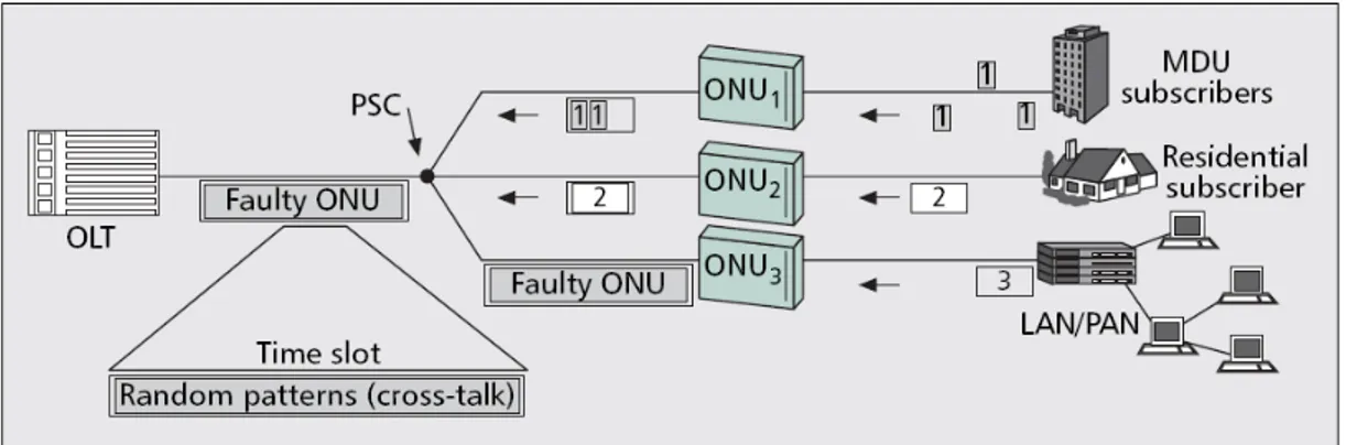
Figure 6. Condition of disturbance
A scenario of a service disruption attack is depicted in figure 6. where the malicious ONU is sending disturbing signal during the time slot of other ONUs. These two signals are combined within the optical splitter/combiner and transmitted on the same optical fiber to OLT. OLT cannot distinguish original signal from disturbance signal and the final result is that received packet is recognized as an incorrect one. As described before, TCP will apply its mechanisms for accurate delivery resulting in the end with reducing bandwidth of attacked ONU or in other words increasing available bandwidth for malicious ONU.
One important thing that should be mentioned here is that intensity of an attack i.e. amount of packets that should be sent in order to destroy upstream transmission of well behaved ONUs depends on type of data that has been attacked. In case of client-to-server we are conducting attack upon data packets. In this case even destroying one frame within sending window will increase value of Frame Error Rate (FER). FER is the ratio between the number of frames that contain an error in frame payload divided by the total number of transmitted frames in one direction. Frames containing errors will be dropped and no ACK messages will be produced for this packets. Based on TCP if we did not acknowledge one of the packets within received sending window also all packets following dropped one will not be acknowledged regardless to the fact that they were maybe received correctly. Absence of ACKs will trigger retransmission timeout at server side and slow start and congestion avoidance will be invoked.
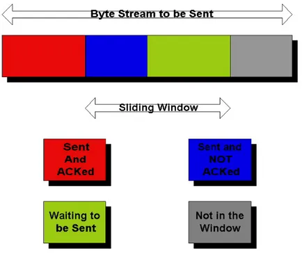
This will cause reduction of both congestion and sending window and as final result client i.e. well behaved ONUs will experience decrease of throughput. On the other hand in the case of server-to-client transmission attacker is destroying ACK messages. Due to sliding window at TCP sender side which in this case is server our attack has to be more intrusive comparing with previous case. The sliding window defines the maximum amount of data that can be sent without having to wait for ACK. (see figure 7)
Figure 7. Working principle of sliding window mechanism in TCP.
.
This means that if we have sliding window size equal to 14 frames that we can send 14 frames before stopping transmission and waiting for first ACK to be returned. In context of degradation attack sliding window size is actually telling us how many ACKs we have to kill in order to trigger retransmission time out and to invoke TCP congestion avoidance procedures. It is worth noting that TCP sliding window uses cumulative acknowledgments. Working principle of cumulative acknowledgments is the following one:
• each ACK is confirming that associated frame has been received successfully • each ACK is also confirming that all frames sent before associated packets were
also received successfully even if associated ACK was not received. This is due to the fact that we can not issue ACK for one frame if previous one was lost or dropped due to the errors.
The rules mentioned above are actually forcing attacker to apply more intrusive attack in order to kill all the ACKs within one sliding window. Killing only some of the ACK messages will not have any influence since ACKs send after destroyed ones will do their job and confirm that packets were received successfully although we did not received associated ACKs.
We can conclude that attacker should be capable of performing two types of attack in order to have successful degradation attack for both types of TCP transmissions ,i.e., for both client-to-server and server-to-client transmissions.
Chapter 3. Evaluation of existing fault detection and
authentication techniques
This chapter concentrates on understanding some mechanisms that are crucial to ensure the security framework in EPONs i.e. methods used to detect an attack upon upstream traffic (from ONU to OLT).
As mentioned before EPONs using TDMA to manage the shared uplink channel are subject to degradation attacks. Malicious ONU is defined as ONU which transmits outside of its allocated time slot and in this way degrades the quality of other properly working ONUs. This degradation is manifested through higher value of Frame Error Rate (FER). This has an effect on congestion management techniques implemented in the higher layers of the protocol stack. In fact, the TCP protocol reacts to higher packet loss by reducing the transmission rate of the source. In this way, malicious ONUs can choke the traffic streams of other ONUs to obtain an unfair amount of resources.
One important difference that should be made here is between faulty and malicious ONUs. As it was mentioned above malicious ONU i.e. attacker transmits disturbing signal with aim to degraded quality of service in the network. This act is done intentionally. On the other hand faulty ONUs are result of natural fatigue of the components present in ONUs. Existing detection and authentication mechanisms which are originally used for detecting faulty ONUs are here described and examined if they can be successfully applied in the case of service disruption attack presence. In the following paragraphs some of current techniques are described and their capability to detect malicious ONUs is examined.
3.1 Detecting methods
This section examines the applicability of current methods for fault ONU detection to degradation attack within EPONs. The supervisory techniques may be broadly arranged into two categories: methods that perform statistical analysis of the communications data (e.g. power detection or optical spectrum analyzers) and methods which measure a signal devoted to diagnostic purposes (e.g. pilot tones and optical time domain reflectometers). In the following we will examine only one method from each group since they are all sharing, more or less, the same problems when detecting degradation attack.
3.1.1 Power detection method
[7] Power detection methods are based on measurement of received optical power over a wide bandwidth. Since all upstream traffic is going towards OLT is logical that power measurements are done within OLT. Measured power is compared with expected value which represent threshold above which communication service will be degraded. Measuring power that is higher that expected one means that we have more than one signal in the communication channel at the same time. Since we can transmit only one signal i.e. one packet at the time having detected more than one signal means that for sure something is going wrong and can be used as indicator that attack is performed.
Typical attack scenario is that one of the stations during idle period i.e. period that station should be shut down starts to transmit.
Information that is sent by the currently working ONU (which is transmitting its packets within assigned time slot) will be combined in the end at the OLT. Applying power detection method received power will be measured and compared with expected values. If number of corrupted bits is sufficiently large OLT will detect presence of bad behaved ONU i.e. malicious one. For example, an attacker can inject disturbing signal only one bit in every period of 10 microseconds.
At the transmission rate of 1Gbps, disturbing signals are present only 0.01% of the time and the average power of data signals together with disturbing signals may not be much different from the average power from data signals alone since power of disturbing signal is not significant “on average”.
Even if statistics are tightly determined, the sporadic nature of the attack may not cause statistical anomalies for a long time, while still affecting the very low Bit Error Rate (BER) that is required (typically 10-11 or less). As a result such an attack may not be detected. Second arising problem is that for this detection method to be able to distinguish between the presence and absence of disturbing signal, an observation of sufficiently large number of corrupted bits is required i.e. we have long detection time. Since optical transmission rates are extremely high, a large amount of data can be affected before any action takes place and this is the reason why short detection times are desirable.
As we can conclude from this brief overview of power detection technique, working principle is quite simple but a lot of problems arise due to statistical nature of this technique. Since attack is mostly occurring in short time periods i.e. it can not be attributed as constant transmission of disturbance light, power detection technique is facing a problem of detecting presence of degradation attack within the network. Knowing that EPONs offer high bit rate transmissions even a little amount of disruption signal, which in average does not change received power enough to cause an alarm, can yield high data losses and noticeable degradation of service in EPON. Eventual change which can be made is increasing threshold values for triggering an attack alarm (detecting presence of faulty/malicious ONU). In this way we can increase sensitivity of power detection method and maybe improve its performances. Note that BER degradation can be consequence of some other causes (e.g. optical fiber losses) than malicious ONU activity can make this change a bad proposal. Power detection will detect presence of badly working ONU, invoke authentication techniques and time that could be used for transmitting data will be waste for searching malicious ONU which in reality does not exists.
3.1.2 Pilot tones
[7] Pilot tones are the signals that travel along the same links as communications data but which are distinguishable from the data. Their purpose is to detect transmission disruptions. Pilot tones are distinguished from communications payload, in TDMA systems, by certain time slots.
Pilot tones will not be effective in detecting attacks unless those attacks cover the same wavelengths at which pilot tones are carried. Possible solution may be seen in subcarrier multiplexed (SCM) signal that is present, in frequency, in the close vicinity of the communication transmission. But even in this case, an attacker may be able to introduce disturbing signal which degrades quality of transmission without significantly affecting the SCM pilot signal.
Therefore, the communications signal can be significantly affected without impinging upon the detection of the pilot tone.
Conclusion that can be made upon this results is that “intelligence” of the attacker inhibits current supervisory techniques in detecting presence of malicious ONU i.e. attacker. Main difference in working principle is that faulty terminal produces disturbing signal all the time i.e. it won’t employ any means of avoiding detection while attacker can produce sporadic or intermittent attacks in such a way to avoid detection.
3.2 Authentication techniques
After having detected that there is improperly working ONU within EPON, the next step is localization of the station that is causing degradation of service within the network. Authentication methods are used in order to locate malicious ONU so that it can be ruled out of the network.
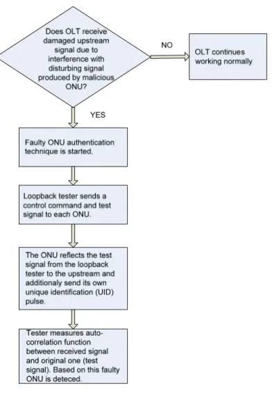
3.2.1 Method 1 – Authentication technique using loopback modulation
In the event that malicious ONU intentionally generates unauthorized optical signal to the OLT, this may prevent, as we mentioned, other ONUs from engaging in data communication, meaning that attacks from single subscriber could seriously impact on all other subscribers as well.
This technique is based on the fact that even if the upstream traffic is corrupted due to disturbance, the ONUs can normally receive a downstream signal from OLT side. In order to distinguish the normal ONUs, their response to the control command from the OLT is checked.
Shortly, when OLT detects (using some of detection techniques that where described in former paragraphs) presence of faulty terminal, it starts faulty authentication technique. First the loopback tester (which is implemented within OLT) will send a control command to each ONU within EPON network and the test signal with PN (pseudorandom noise) pattern. Each ONU will reflect the test signal from the loopback tester to the upstream and the tester will then measure the auto correlation function corresponding to the received optical power of the upstream light from the ONU. Also each ONU additionally sends its own unique identification so that each ONU can be located. Based on the measurements that are then done within OLT, faulty ONU is detected and allocated [8].
Figure 8. Flowchart of method 1
First problem that can arise is that during initial registration, which is activated before ONU starts to transmit data and during which each participating ONU obtains its own ONU ID, ONU applies masquerading attack i.e. due to broadcast downstream traffic ONU extracts MAC address and masquerade as another ONU. An OLT does not have any way of detecting if some ONU is presenting himself as another ONU. Using false ID malicious ONU can transmit disturbing light and then during authentication technique it can present as another ONU. In this way wrong ONU will be ruled out of the network and malicious ONU will achieve its primal goal- gain resources in the network. This problem is resolved by implementing low speed modulation function into each ONU so that it can have an own unique identification (UID). In this way service disruption attack combined with masquerading is solved.
Second problem that arises using this technique is the assumption that is made in the case of the faulty terminal and that is in general, when there is no traffic to be transmitted from the ONU, a time slot will be filled with an idle signal. Therefore, the idle pattern is the most likely cause of light disturbance and during auto correlation ”evaluation” idle pattern will be used as source of disturbance light. This assumption is the main reason why this technique fails to detect ONU which is intentionally producing disturbance light.
Malicious ONU will use disturbance light which has much higher power that idle signal, so during auto correlation “evaluation” obtained results will be wrong since OLT expects that disturbance light resemble to idle signal.
The final conclusion that can be made is that difference between faulty terminal behavior and malicious ONU behavior is the crucial difference that should be taken in consideration while testing which ONU is source of disturbing light. Since faulty ONUs are “stupid” i.e. their actions are not led by idea to decrease service quality in the network, they are acting in the same way all the time and they are not trying to hide or masquerade their presence or identity. On the other hand malicious ONU are “intelligent” and they are aware of the fact that network will try to discover them so their behavior is changing dynamically based on current status of the network.
This technique might be adopted for detecting faulty and malicious ONU by introducing various patterns based on which auto correlation function would work. According to power spectrum of disruption signal i.e. intensity of disturbance light different patterns would be used. Possible problem for this solution is authentication time or in other words time that is required to check all the different patterns in order to detect malicious ONU.
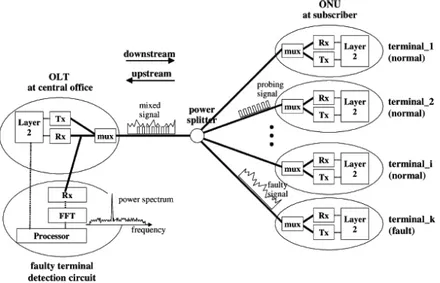
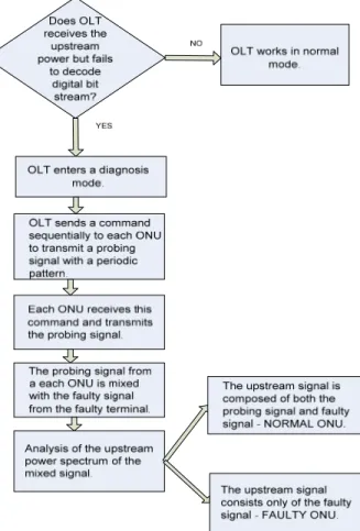
3.2.2 Method 2 – Authentication technique using periodic probing signal
[9] Unlike a previous method, this one is based on usage of probing signal and the frequency analysis technique. When improperly working ONU is discovered OLT stops its normal operation and enters a diagnosis mode. In diagnosis mode OLT examines all registered ONU terminals one-by-one according to the following steps. First, the OLT sends a command sequentially to each ONU to transmit a probing signal with a periodic pattern (like a periodic rectangular signal). Second, each normal ONU receives the command and transmits the probing signal. Third the probing signal from the normal ONU is mixed with the faulty signal from the faulty terminal. Finally by analyzing the upstream power spectrum of the mixed signal and comparing its power spectrum in each step at the OLT, the commanded terminal can be validated whether it is normal terminal or not.
For example, when a normal terminal is commanded, the upstream signal is composed from both the probing signal and the faulty signal. On the other hand, when the faulty terminal is commanded, the upstream signal is composed from only faulty signal. The faulty terminal detection circuit can differentiate these two cases and found out the faulty terminal easily by comparing power measurement after a bandpass filter.
If we take in consideration following situation - malicious terminal is transmitting constantly disturbance light in order to gain as much network capacity as it can. OLT detects service degradation within PON and starts with diagnosis mode.
Mixed signal from all normal stations will be composed from disturbance light and probing signal. When probing signal command reaches malicious ONU, it will transmit only probing signal. This information could be parameter that can be used to allocate malicious ONU. Main problem in this so-called solution is that attacks are mostly sporadic and it can very easily happen than during diagnosis mode neither of stations will be detected as malicious since all of them will respond correctly i.e. received signals at OLT will be composed only from probing signals without disturbance light.
Final conclusion that can be made is that sporadic nature of attacker behavior makes this technique to fail in detecting malicious ONU. It might be used for narrowing the list of possible malicious ONU. Knowing that received signal at OLT that was sent from
malicious ONU cannot be composed from more than one signal i.e. probing signal, we can label all stations whose final signal was composed from both disturbance light and probing signal as well behaved ONUs.
In the end we can conclude that existing techniques for detecting and authentication of faulty terminals are not well suited for detecting and locating malicious ONUs. Main problems that these techniques are facing are attacker “intelligence” and sporadic (random) nature of attacks. While in the case of faulty terminal it is assumed that terminals will transmit constantly or more frequent disturbing light and that this kind of terminals will not be able to respond to commands sent from OLT in the case of degradation attack we have different situation. The malicious station can randomly choose the transmission times of the interfering sequences, resulting in an increased FER for all other ONUs sharing the PON. Alternatively, the malicious station can focus on ONU that have a higher throughput and, therefore, are more fragile to an increase in FER. In other words attack frequency is variable and we cannot relay on the assumption that disturbance light will be present constantly.
Malicious ONUs are also aware that when authentication procedures are invoked they should be well behaved in order to stay undetected.
Also we should mention that efficiency of faulty terminal authentication techniques in case of degradation attack largely depends on the level of the intelligence of the attacker. In case of having attacker that is capable of recognizing probe or testing signal both of presented authentication techniques fail because upon detecting probe or testing signal attacker will stop causing collisions in the network and lay low for some time in order to stay undetected. On the other hand for attackers that are not capable distinguishing when diagnosis mode is invoked and when not this techniques could be used since behavior of malicious ONU will not be so much different from one of faulty terminal.
Chapter 4. Implementation of degradation attack in
OMNeT++
In this chapter we will explain some basic functionalities of network simulator OMNeT++ which was used in order to implement degradation attack in EPON. The basic
functionalities of network architecture of EPON was created and implemented in OMNeT++ by Andreas Bodozoglou .
4.1 OMNeT++
OMNeT++ is a component-based, modular and open-architecture discrete event network simulator. Mostly it is used for simulation of computer networks but it can be also used for queuing network simulations, validating hardware architectures and modeling any other system where the discrete event approach is suitable.
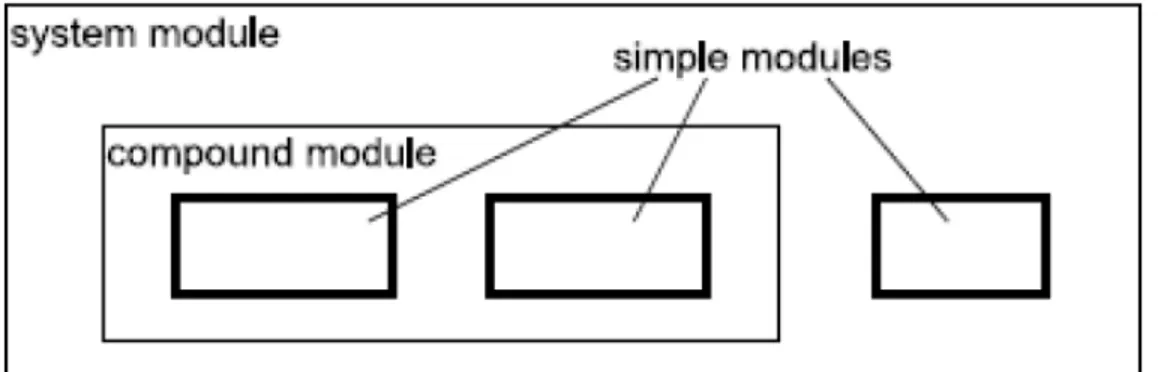
The OMNeT++ model is a collection of hierarchically nested modules as shown in figure 11. The top-level module is also called the System Module or Network. This module contains one or more sub-modules each of which could contain other sub-modules. The module can be nested to any depth and hence it is possible to capture complex system models in OMNeT++. Modules are distinguished as being either simple or compound. A simple modules form the lowest level of the module hierarchy and they are the main building blocks of every simulation. Compound modules are aggregates of simple modules and their behavior is final result of actions associated simple modules. One simple module can be for example TCP implementation, the other one Ethernet implementation and together they can form an Internet host which represents then compound module.
In an OMNeT++ model, modules communicate by exchanging messages. In an actual simulation, messages can represent frames or packets in a computer network, jobs or customers in a queuing network or other types of mobile entities. Messages are sent out and arrive through gates, which are the input and output interfaces of a module. Input and output gates of different modules can be interconnected. Each connection is created within a single level of the module hierarchy: within a compound module, one can connect the corresponding gates of two sub-modules, or a gate of one sub-module and a gate of the compound module. Due to the hierarchical structure of the model, messages typically travel through a series of connections, to start and arrive in simple modules. OMNeT++ also allows that modules send messages to themselves. In this way each module can schedule an event in later time. Compound modules act as 'cardboard boxes' in the model, transparently relaying messages between their inside and the outside world. Modules can have parameters. Parameters are used for two main purposes: (1) to customize simple module behavior, and (2) to parametrize model topology. Compound modules can pass parameters or expressions of parameters to their sub-modules. A simulation in OMNeT++ is written in two different languages, NEtwork Description (NED) language and C++. These two languages separate design of a topology and the implementation of modules that exist in this topology.
The NED language is used to describe the layout (topology) of the simulation, i.e., with NED language we can define three main, distinctive elements of our model:
• Module definition - in this blocks simple and compound modules are defined and values of associated parameters are set. Also here we can define gates that connect the modules.
• Channel definition - describe channels (links) that connect modules.
• Network definition - to get the whole simulation running, we have to describe which module is the top level module of our network. This top level module is an instance of the system module.
The implementation of the modules defined in the NED language is done in C++,i.e., C++ is used to define behavior of defined modules.
4.1.1 Basic methods, functions and classes
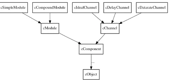
Components, Simple Modules, Channels
OMNeT++ simulation models are composed of modules and connections. As it was mentioned above modules may be simple modules or compound modules: simple modules are the active components in a model, and their behavior is defined by the users as C++ code. Connections may have associated channel objects. Channel objects encapsulate channel behavior: propagation and transmission time modeling, error modeling and possibly others.