D265ModTPhD/EN00 Phd Course BioRobotics
Academic Year
2020/2021 ISBN: XXXXXXXXXXXXThesis Title
Hybrid Soft-Rigid: An effective
approach for enhancing capabilities
of soft robots
Author
Canberk SözerSupervisor
Prof. Dr. Arianna Menciassi
Tutor
3
Abstract
Despite its relatively young history, soft robotics has become increasingly popular due to its salient advantages, such as compliance and deformability, allowing for safe adaptation and interaction with unstructured environments. However, such an inherent softness brings along limited load capability and narrow stiffness range, combined with controllability and predictability challenges which hinder enabling their strong potential and widening their real-world application areas.
In this context, one objective is developing solid structures able to tune their stiffness in a controllable way. To achieve this goal, this Thesis addresses the development of novel low-cost structures based on the hybrid soft-rigid (HSR) approach. It relies on combining materials with different mechanical properties to benefit from the main advantages of both soft (i.e., structural compliance and many degrees of freedom) and rigid (i.e., force generation and precision) structures, while overcoming some of their respective limitations.
The study and development of a novel variable stiffness revolute joint (VSRJ) is firstly reported, as a fundamental component for many HSR designs. The VSRJ provided up to 8-fold controllable stiffness enhancement through air pressure, regardless of its position and with high repeatability. Secondly, the integration of a stiffness control structure (SCS) -built through the assembly of three downscaled VSRJs- into a soft manipulator is presented to demonstrate the effective potential of the proposed variable stiffness concept in terms of position-independent stiffness control and enhanced precision of the path followed by the manipulator end-effector. Thirdly, a module that combines actuation, proprioceptive sensing, and variable stiffness is presented. The module was proposed as a modular solution able to mitigate the tubing challenge -by reducing the number of the required tubes in the overall system- which is typical in fluidic systems. The design, experimental characterization, and a demonstration of the module were presented.
Overall, the Thesis proposes a set of solutions to show the potential of the hybrid soft-rigid approach to enhance the capabilities of the soft robots in terms of force, stiffness range, controllability, precision, and modularity.
5
Acknowledgments
I would like to express my sincere gratitude to my supervisor Prof. Arianna Menciassi for her continuous guidance and support. Also, many thanks to my tutor Prof. Leonardo Ricotti for all his mentorship.
I will also take this opportunity to thank Prof. Barry Trimmer who gave me an opportunity in his lab where my journey in soft robotics has begun, and I gained my first hands-on experience.
The deepest thanks go to my lovely wife Aylin, my buddy Ani, and my dear family Zeren, Ali, and Tuğberk for their continuous emotional support and just believing in me.
Finally, I want to thank my friends and lab mates for their support in this journey. It has been a great opportunity and pleasure being a part of the Surgical Robotics group.
7
Table of Contents
List of Tables ... 11 List of Figures ... 13 List of Abbreviations ... 19 List of Appendice ... 21 1. Introduction ... 23 1.1. Motivation ... 23 1.2. Contribution ... 25 1.3. Scientific production ... 262. Comparative literature review of soft robotics and hybrid soft-rigid (HSR) approach ... 29 2.1. Design ... 29 2.1.1. Actuation ... 29 2.1.1.1. Fluidic actuation ... 31 2.1.1.2. Thermal actuation ... 36 2.1.1.3. Motor-tendon actuation... 38 2.1.1.4. Electrical actuation ... 39 2.1.2. Variable stiffness ... 40
2.1.2.1. Elastic properties change ... 42
2.1.2.2. Actuator-like solutions ... 45
2.1.3. Sensing ... 46
2.1.4. Modularity ... 49
2.2. Material and fabrication ... 50
2.3. Modeling and control ... 52
8
2.5. Devices and applications ... 54
2.6. Conclusion ... 56
3. Pressure-controlled revolute joint with variable stiffness ... 57
3.1. Introduction ... 57
3.2. Materials and methods ... 59
3.2.1. General overview... 59
3.2.2. Parameters of the VSRJ ... 61
3.2.3. Material selection and characterization ... 64
3.2.3.1. Friction test ... 64
3.2.3.2. Material characterization ... 66
3.2.4. Manufacturing ... 68
3.3. Results ... 69
3.3.1. Contribution of the friction and bump formation ... 70
3.3.2. Finite element modelling ... 72
3.3.3. Repeatability result ... 75
3.3.4. Torque result... 77
3.3.5. Stiffness result ... 77
3.4. Discussion and conclusion ... 80
4. Pressure-controlled manipulator with variable stiffness structure ... 83
4.1. Introduction ... 83
4.2. Design of the manipulator ... 85
4.2.1. Fiber-reinforced actuator ... 85
4.2.2. Stiffness control structure ... 86
4.3. Fabrication process ... 87
9 4.3.2. SCS fabrication ... 88 4.4. Results ... 89 4.4.1. Compliance test ... 91 4.4.2. SCS stiffness test ... 92 4.4.3. Position test... 93
4.4.4. Controllable stiffness test ... 95
4.5. Discussion and conclusion ... 96
5. Towards multifunctional hybrid soft-rigid module ... 99
5.1. Introduction ... 99
5.2. Materials and methods ... 100
5.2.1. Overview ... 100 5.2.2. Manufacturing ... 104 5.2.3. Experimental setup ... 105 5.3. Results ... 106 5.3.1. Actuation ... 106 5.3.2. Proprioceptive sensing ... 108 5.3.3. Variable stiffness ... 111
5.3.4. Integration of three modules ... 114
5.4. Discussion and conclusion ... 115
6. Conclusion ... 119
Appendix A. Design and development of a miniaturized intra-abdominal flexible HIFU system ... 125
A.1. Introduction ... 125
A.2. Materials and methods... 126
A.3. Results ... 129
10
11
List of Tables
Table 2.1 The summary of the advantages and disadvantages of actuation methods
for soft and hybrid robots: fluidic, thermal, motor-driven, and electrical. ... 30
Table 2.2 The summary of the advantages and disadvantages of stiffness control
methods for soft and hybrid robots: elastic properties change and actuator-like solutions. ... 41
Table 2.3 The summary of the advantages and disadvantages of sensor types that
are used in soft and hybrid robots: resistive, capacitive, optical, magnetic, and inductive. ... 47
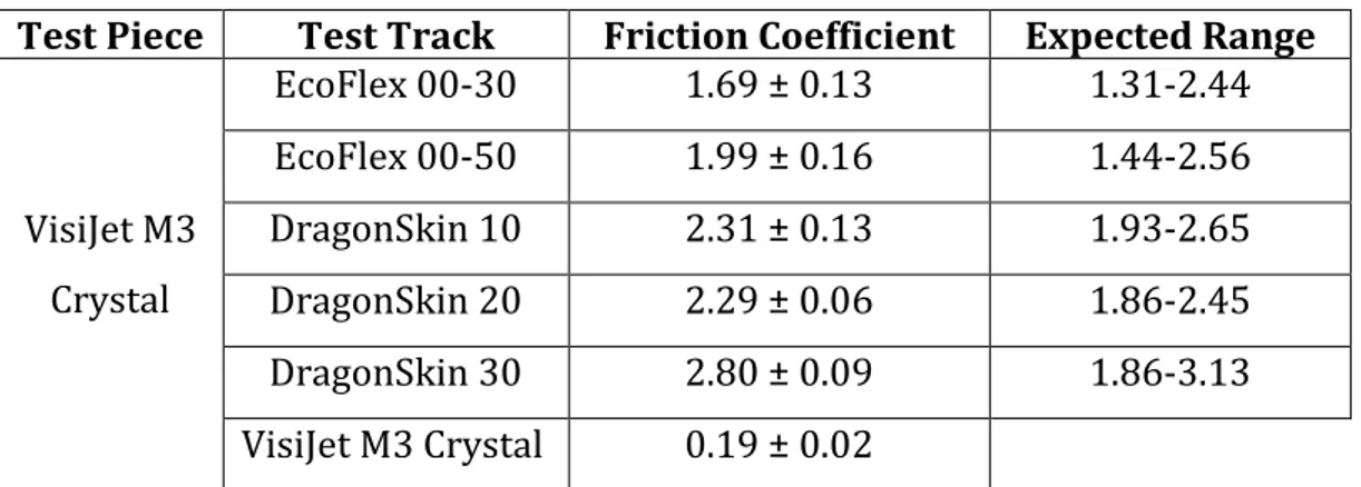
Table 3.1 Friction coefficients of tested silicone rubber-plastic and two plastic
samples. ... 66
Table 4.1 The applied displacements and resultant rotation angles to be used in the
compliance, SCS stiffness, and controllable stiffness tests. ... 91
Table 4.2 Position of the manipulator end effector with and without the SCS during
pressurization and depressurization. The results are given in the x-y plane. Red and blue tones represent the manipulator without and with the SCS, respectively. ... 94
13
List of Figures
Figure 1.1 Quantitative change of four manipulator features: precision, structural
compliance, degrees of freedom, and force exertion (adapted from [14]). The human hand is a natural equivalent of hybrid structures: while soft muscles/tendons provide dexterous positioning and adaptability, rigid bones enhance structural strength and force transmission. ... 24
Figure 2.1 Some fluid actuated soft and hybrid robots. (a) McKibben actuator [29];
(b) flexible microactuator [33]; (c) fast-PneuNet [34]; (d) fiber-reinforced soft bending actuator [35]; (e) hybrid fast-PneuNet which is created by inserting rigid structures in the fast-PneuNet [36]; (f) a hybrid actuator which is fabricated by combining soft and hard elastomeric materials [37]; (g) translational, bending, and rotational modules based on the hybrid approach [38]; (h) soft machine control through vacuum enabled buckling [39]; (i) vacuum actuated hybrid gripper [40].32
Figure 2.2 SMA controlled (a) soft actuator for bending and twisting [77] and (b)
hybrid gripper for bending [78]. ... 37
Figure 2.3 Motor-tendon driven (a) octopus arm [85] and (b) hybrid finger which
includes pressure-controlled variable stiffness joints [92]. ... 39
Figure 2.4 Electrically controlled (a) adhesion enabled soft gripper [95] and (b)
hybrid actuator made of dielectric elastomer [98]. ... 40
Figure 2.5 Variable stiffness through controlling the elastic properties of materials
(a-d) and structures (e, f). LMPA embedded (a) magnetic driven catheter [9] and (b) hydraulic-driven manipulator [107]. SMP controlled (c) soft actuator [10] and (d) hybrid gripper [17]. (e) Granular [6] and (f) layer [112] jamming mechanisms. .... 43
Figure 2.6 Variable stiffening through active-active (a, b) and active-passive (c, d)
approaches. Antagonistic control of (a) pneumatic artificial muscles [123] and (b) pressure-tendon length [125]. Active-passive combination of pressure chamber- (c) meshed structure [126] and (d) rigid encapsulation [128]... 46
Figure 2.7 Some driving hardware for pneumatic actuations. (a) Soft pump
powered by artificial muscles [216]; (b) motor-driven soft origami [217] and (c) stretchable [218] pumps; (d) bistable valve [220]. ... 54
14
Figure 2.8 Manipulation (a, b), locomotion (c, d), and wearable and rehabilitation
(e, f) applications of soft and hybrid robots. (a) Soft surgical manipulator [8]; (b) bio-inspired gripper [226]; (c) hybrid approach for multimode operation [228]; (d) spine-inspired locomotion [57]; (e) soft glove for hand rehabilitation [1]; (f) multipurpose actuation for assistance[209]. ... 55
Figure 3.1 (a) Components of the VSRJ. Length (l) = 40 mm, width (w) = 20 mm, and
height (h) = 7 mm; (b) assembled VSRJ; (c) schematic representation of different possible angles (-ϕ°, -ϕ/2°, 0°, ϕ/2°, and ϕ°) and input pressures (P = 0 and P ≠ 0). ... 60
Figure 3.2 Acting torques on the VSRJ. ... 61 Figure 3.3 Components of the τreaction. ... 62
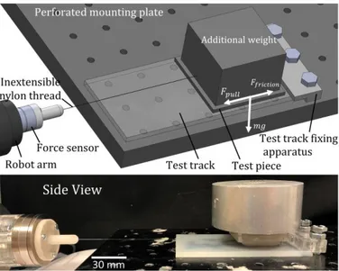
Figure 3.4 Experimental setup for the friction tests of raw materials: schematics
(top) and side view (bottom). ... 64
Figure 3.5 Experimental results of the friction tests between tested silicone rubbers
(EcoFlex 00-30, EcoFlex 00-50, DragonSkin 10, DragonSkin 20, and DragonSkin 30) – 3D printed plastic (VisiJet M3 Crystal) and two plastic materials. ... 66
Figure 3.6 Strain-stress curves for tensile loading, tensile unloading, compressive
loading, and compressive unloading of EcoFlex 00-50 silicone rubber. ... 67
Figure 3.7 (a) Assembling of 3D printed mould parts; (b) mixing the A and B parts
of silicone; (c) eliminating the entrapped air using vacuum chamber; (d) pouring silicone into the mould; (e) integration of pressure pipe and alignment pins with the chamber; (f) completed chamber; (g) assembling of the chamber and 3D printed rigid links; (h) assembled VSRJ. ... 68
Figure 3.8 Experimental setup to characterize the VSRJ: schematics (top) and top
view (bottom). ... 69
Figure 3.9 Experimental data of the measured force angle of the VSRJ from -30° to
+30° rotation at 0-5 bar pressure with an interval of 1 bar. ... 70
Figure 3.10 Fitted hyperelastic models to (a) tensile and (b) compressive loading of
EcoFlex 00-50 silicone rubber. ... 72
Figure 3.11 FEM simulation results are presented together with the respective
-15
30° to +30° at 5 bar. The cross-section images are obtained by coloring the silicone to black for visualization purposes, cutting the VSRJ transversally, and gluing a transparent plexiglass layer on top of it. After pressurization, the deformation of the silicone chamber can be observed. The legend represents von Misses stress. ... 74
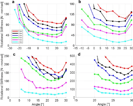
Figure 3.12 FEM simulation results of the rotational stiffness-angle relationship in
the +τ direction corresponding to (a) 60°; (b) 45°; (c) 30°; (d) 15° rotation. ... 74
Figure 3.13 Experimental setup for repeatability tests. ... 75 Figure 3.14 Repeatability test results of the VSRJ during 100 cycles. The chamber is
pressurized at (a) 1 bar; (b) 2 bar; (c) 3 bar; (d) 4 bar; (e) 5 bar. ... 76
Figure 3.15 Experimental results of torque-angle curves. ... 78 Figure 3.16 Experimental results of the rotational stiffness-angle relationship. The
solid line represents the mean, and the shaded area represents the standard deviation. ... 79
Figure 3.17 Average stiffness change corresponding to the applied pressure from 0
to 5 bar with an interval of 1 bar in (a) 60°; (b) 45°; (c) 30°; (d) 15° rotation. ... 80
Figure 4.1 Prototype (left) and solid model (right) of the developed manipulator.
FRA: Fiber-reinforced actuator, SCS: Stiffness control structure and EL: Encapsulation layer. ... 85
Figure 4.2 View of the FRA with wrapped fiber element (black helix). lFRA: 90 mm,
wFRA: 20 mm, rFRA: 7 mm. ... 85
Figure 4.3 (a) Components of the hybrid soft-rigid joint concept (left), assembled
joint (right); (b) A-A cross-section of assembled joint with unpressurized (left) and pressurized (right) pressure chambers in the rigid compartment (by pressurization, increasing stress at the contact surface is represented by dashed black line); (c) assembled SCS. lSCS: 100 mm, wSCS: 10 mm, hSCS: 8 mm. ... 87
Figure 4.4 (a) Components of the manipulator: i) inextensible nylon fiber as a
reinforcement element; ii) unreinforced silicone actuator; iii) encapsulation layer;
iv) SCS and (b) completed manipulator. ... 88
Figure 4.5 (a) Pouring DragonSkin 10 silicone into the mold of the first layer of the
FRA; (b) fiber wrapping, (c) pouring DragonSkin 10 into the mold of the second layer of the FRA; (d) completed FRA; (e) pouring DragonSkin 10 into pressure chamber
16
mold; (f) integration of the cured pressure chamber with the alignment pins and a pressure pipe; (g) assembly of the SCS parts; (h) pouring DragonSkin 30 silicone into the mold of encapsulation layer; (i) completed encapsulation layer; (j) gluing FRAs, the SCS and the encapsulation layer; (k-l) capping and pressure pipe integration; (m) completed manipulator which is given with tubing arrangement. ... 89
Figure 4.6 r1 and r2 represent FRAs. r3, r4, and r5 represent the pressure chambers
from the base to the end effector. g: gravity force. ... 90
Figure 4.7 Experimental result of the input pressure to r1 - manipulator stiffness
relationship with and without SCS. The mean and the standard deviation of the 10 trials are given. ... 92
Figure 4.8 Experimental results of the input pressure (at r3, r3 - r4, and r3 - r4 - r5) -
joint stiffness relationship. The mean and the standard deviation of the 10 trials are given. ... 93
Figure 4.9 Experimental setup for magnetic position tracking. The prototype lays
on a horizontal table. ... 93
Figure 4.10 Experimental setup for manipulator stiffness measurement. ... 95 Figure 4.11 Experimental results of the input pressure - manipulator stiffness
relationship. The mean and the standard deviation of the 10 trials are given. ... 96
Figure 5.1 (a) Prototype (left) and solid model (right) of the module; (b) rigid, rigid
but compliant, and soft components of the module; (c) actuation and (d) variable stiffness mechanisms of the module. ... 101
Figure 5.2 Schematic representation of the modularity in the case of serially
integrated three modules. ... 103
Figure 5.3 (a) Pouring EcoFlex 00-50 silicone rubber into a 3D printed cylindrical
mold; (b) tubing of the soft actuator and placing into spring; (c) pouring DragonSkin 10A silicone rubber into a 3D printed mold; (d) assembling fabricated spring-reinforced actuator and stiffness pads with 3D printed rigid components; (e) assembled module. ... 105
17
Figure 5.5 During experiments, given notation was followed. A1, A2, and A3
represent Actuator 1, Actuator 2, and Actuator 3, respectively. The numbering is also valid for sensors. ... 106
Figure 5.6 Experimental setup for tracking the module tip. ... 107 Figure 5.7 (a) Workspace of the module tip in 3D space; (b) experimental results of
the input pressure-bending angle relationship. The mean (solid line) and standard deviation (shaded area) of the 5 experiments are given when the A1 is pressurized (left), the A2 is pressurized (middle), and the A3 is pressurized (right). The arrows represent the bending directions. ... 107
Figure 5.8 Experimental result of the input pressure-output force relationship
while the module is fixed at initial positions of 0° (a-f) and 30° (g-l). The mean (solid line) and standard deviation (shaded area) are given for 5 trials for each curve. The arrows show the direction of force generation. ... 109
Figure 5.9 (a) Circuit diagram; (b) experimental setup for measuring the input
pressure, sensor data, and the tip position of the module simultaneously. ... 110
Figure 5.10 Experimental result of bending angle-sensor output relationship.
Simultaneous measurement of the S1, S2, and S3 voltages is shown when the (a) A1, (b) A2, and (c) A3 is pressurized. The experiments were repeated 5 times, and the curves were fitted for each group. ... 110
Figure 5.11 Experimental result of the stiffness of the module with the flat-surfaced
ball joint (red) and the ball joint with dents (green). The standard deviation is given for 5 experiments. ... 112
Figure 5.12 Experimental results of the stiffness corresponding to the pressure (0
to 500 kPa with an interval of 100 kPa) at the stiffness pads. The stiffness results while the manipulator at (a) 0° initial position (no pressure at the actuators); (b) 30° when the only one actuator was pressurized; (c) 30° when two actuators were pressurized. The standard deviations are given for 5 trials for each bar graph. The white arrows represent the motion direction of the force sensor which is moved by the robot arm. ... 113
Figure 5.13 Possible positions of the manipulator which was built by integrating
18
the A1 was pressurized; (c) the A2 was pressurized; (d) the A3 was pressurized; (e) the A2 and A3 were pressurized. To achieve (f): i) the A2 and A3 were pressurized;
ii) the stiffness pads of Module 1 were pressurized; iii) the A2 and A3 were
depressurized; iv) the A1 was pressurized. To reach the shape in (g): i) the A1 was pressurized; ii) the stiffness pads of Module 1 and 2 were pressurized; iii) the A1 was depressurized; iv) the A2 and A3 were pressurized. ... 115
Figure A.1 (a) Solid model of the proposed device, characterized by the soft
manipulator equipped with the custom HIFU transducer; (b) picture of the bent device in contact with the ex vivo tissue. ... 127
Figure A.2 Interaction between the miniaturized HIFU transducer (on the right) and
a soft tissue in a restricted environment scenario. ... 128
Figure A.3 Induced thermal lesion on the ex vivo chicken breast. (HIFU focus at 3
19
List of Abbreviations
ABS: Acrylonitrile Butadiene Styrene DEA: Dielectric Elastomer Actuator FBG: Fiber Bragg Grating
FEM: Finite Element Method FRA: Fiber-Reinforced Actuator
HIFU: High Intensity Focused Ultrasound HSR: Hybrid Soft-Rigid
LMPA: Low Melting Point Alloy MIS: Minimally Invasive Surgery PAM: Pneumatic Artificial Muscle PDMS: PolyDiMethylSiloxane SCS: Stiffness Control Structure SMA: Shape Memory Alloy SMP: Shape Memory Polymer
21
List of Appendice
Appendix A. Design and development of a miniaturized intra-abdominal flexible HIFU system……….. 125
23
1. Introduction
1.1. Motivation
Conventional rigid-bodied robots show remarkable performance in repetitive tasks. They are able to couple high force/speed requirements and high precision and accuracy in structured environments, such as a production line. However, they are generally lacking compliance and need a huge effort to interact with an unstructured environment safely.
On the contrary, soft-bodied robots show inherent compliance. This feature gives them superiority in terms of safe interaction, adaptability to their surroundings, and flexibility compared to rigid counterparts. Pioneering attempts have demonstrated the dexterous adaptation ability of soft robots, even in an unpredictable environment, such as in the presence of humans or delicate objects [1]–[4], avoiding a complex control scheme. Therefore, they have great potential to bridge the gap between people and machines [5].
However, inherent softness brings along low force output and narrow stiffness range combining with difficulties in controllability and predictability. Researchers have demonstrated the adaptability of soft robots widely. On the other hand, low force output still has room for further improvements. This is one of the main challenges which hinders increasing the real-world applications of soft robots. Because in addition to adaptability to an object, it is also expected to generate enough output force to manipulate it. To overcome these limitations, various variable stiffness strategies have been proposed and applied to soft robots, for example, jamming [6]–[8] and smart materials [9], [10]. Although they are solid methods, there is no generalized solution to provide variable stiffness for different applications. Moreover, reinforcement elements have been introduced to address the controllability and predictability, for example, through limiting the expansion of a deformable pressure chamber [11]–[13]. Although this method enhances the controllability effectively, it has no major effect on
24
increasing the output force. If higher pressure is applied to obtain a higher force output, they may fail through ballooning or bursting.
In this context, the hybrid soft-rigid (HSR) approach is an effective method that combines materials with different mechanical properties to benefit from the main advantages of soft (i.e., structural compliance and many degrees of freedom) and rigid (i.e., force exertion and precision) structures [14], as illustrated in Figure 1.1. In this approach, a soft actuator is combined with rigid structural elements which are used for force transmission, aiming to increase both force output and controllability by limiting the deformation of the soft material.
Figure 1.1 Quantitative change of four manipulator features: precision, structural compliance, degrees of
freedom, and force exertion (adapted from [14]). The human hand is a natural equivalent of hybrid structures: while soft muscles/tendons provide dexterous positioning and adaptability, rigid bones enhance structural strength and force transmission.
From the motion ability perspective, while soft materials deform continuously, rigid structures need joints for motion. Therefore, to merge the two fields (i.e., soft robotics and rigid robotics), novel hybrid joints are needed. In this context, the integration of a variable stiffness structure into a joint can enable stiffening and, as a consequence, more precise motion control [15]–[17], which are challenging in entirely soft robots.
25
This Thesis proposes three original solutions with high output force and wide stiffening range combining with enhanced controllability, predictability, precision, and modularity. In all of these studies, the methodology relies on limiting the expansion of a pneumatically-driven soft actuator by a rigid structural element, thus enabling novel and high-performance designs.
1.2. Contribution
The first contribution of this Thesis consists of developing a variable stiffness structure by controlling the deformation of soft inflatable chambers within a rigid encapsulation. The second contribution is integrating the developed structures with pneumatic actuators to achieve a manipulator with position-independent stiffness capability. As a third contribution, a solution for a real and effective adoption of the developed concepts was targeted by addressing the typical tubing challenge of fluidic-driven modular structures. A novel solution was proposed to reduce the number of tubes added while integration new modules. The specific contributions of this Thesis are described in the following chapters:
Chapter 2 provides a thorough and state-of-the-art comparative discussion of soft and HSR robots in terms of design (i.e., actuation, variable stiffness, sensing, and modularity), material and fabrication, modeling and control, driving hardware, and devices and applications.
Chapter 3 presents a variable stiffness revolute joint (VSRJ). A novel method was proposed to control the stiffness of a structure in a revolute joint form through air pressure. The modular and scalable structure of the VSRJ offered a stiffness control mechanism regardless of its position. A prototype was designed, and the design was simulated using the finite element method (FEM) considering material properties and geometry. Then, the prototype was fabricated through 3D printing and molding techniques. Finally, experimental tests in terms of repeatability, torque, and rotational stiffness were carried out, and a good match between experimental results and FEM simulations was obtained.
26
Chapter 4 demonstrates how the VSRJ concept can be used to tune the stiffness of a manipulator regardless of its position. To achieve it, the VSRJ -presented in Chapter 3- was downscaled, and a stiffness control structure (SCS) was built by the assembly of three VSRJs to demonstrate scalability and modularity, respectively. To reduce the control complexity and the setup cost, air pressure was used to regulate both actuation and stiffening. A prototype was designed and fabricated through 3D printing and molding techniques. The SCS was embedded into a manipulator, which consisted of two fiber-reinforced actuators (FRAs) for bidirectional in-plane positioning. Finally, it was demonstrated that the stiffness of the manipulator can be tuned regardless of its position through controlling the stiffness of the VSRJs. Moreover, enhancement in the precision of the path followed by the manipulator end-effector was reported.
Chapter 5 reports a novel module to increase the modularity of fluid-operated systems by reducing the number of tubes while integrating multiple modules serially. In addition to independent actuation and variable stiffness capabilities -presented in Chapter 4-, proprioceptive sensing feature was introduced. Moreover, the presented in-plane motion ability in Chapter 3 and 4 was enhanced into 3D space. The design, fabrication, and experimental characterization of the module were presented.
Chapter 6 concludes the Thesis. This chapter includes summaries and limitations of the presented works and future directions.
1.3. Scientific production
This Thesis is written through benefitting the publications below. Some findings are not published yet.
Journal Articles
• Sozer C and Menciassi A A comprehensive review on soft robotics: Design, Material, Modeling, and Applications. To be submitted
• Sozer C, Sahu SK, Tamadon I and Menciassi A Towards multifunctional hybrid soft-rigid module. To be submitted
27
• Sahu SK, Sozer C, Renaud P and Menciassi A Shape Reconstruction Process in Minimally Invasive Surgery: state of the art, progress, and future directions. To be submitted
• Sozer C, Paternò L, Tortora G and Menciassi A A novel pressure-controlled revolute joint with variable stiffness. Under Review – Soft
Robotics
Conference Proceedings
• Sozer C, Paternò L, Tortora G and Menciassi A 2020 Pressure-Driven Manipulator with Variable Stiffness Structure In 2020 IEEE International
Conference on Robotics and Automation (ICRA) 696-702.
• Sozer C, Cafarelli A, Brancadoro M and Menciassi A 2018 Design and development of a miniaturized intra-abdominal flexible HIFU system: a proof of concept The Hamlyn Symposium on Medical Robotics 11 1-2.
29
2. Comparative literature review of soft robotics and
hybrid soft-rigid (HSR) approach
Soft robots are classified as a subgroup of continuum robots [18]. Some continuum robots show flexible and soft characteristics, even if they are composed of rigid materials, entirely [19]–[24]. In this literature review, only completely soft and hybrid soft-rigid (HSR) robots were discussed, so those robots made of rigid material -even if they have compliance due to their structure- were excluded. In HSR robots, rigid materials are used as a structural element to improve the functional performance of the robot (e.g., increasing force output). This should be defined because some methods include rigid parts, for example, rigid tendons and springs for actuation or rigid permanent magnets for sensing. However, these rigid parts are used for positioning or adding new functionalities, but not for advancing the performance of the robots. The word
hybrid will be used to refer to HSR robots within the rest of the Thesis.
This chapter discusses design (Section 2.1), material and fabrication (Section 2.2), modeling and control (Section 2.3), driving hardware (Section 2.4), and devices and applications (Section 2.5) for the soft and hybrid robots. To be noted that the research outputs of hybrid robots are still way more limited than soft robots.
2.1. Design
In this section, design criteria for soft and hybrid structures were discussed. The design criteria have been broken into 4 subsections, which are the most relevant ones based on the structure and aim of the Thesis.
2.1.1. Actuation
There are various methods for actuating soft and hybrid robots. However, four common approaches were reviewed, namely fluidic, thermal, motor-tendon, and electrical. A comparative study based on the performance of the various traditional and innovative actuation strategies is given in [25]. The advantages
30
and disadvantages of the reviewed actuation methods are summarized in Table 2.1.
Table 2.1 The summary of the advantages and disadvantages of actuation methods for soft and hybrid
robots: fluidic, thermal, motor-driven, and electrical.
Actuation Method Advantages Disadvantages
Fluidic Pneumatic [8], [11], [26]-[38], [41]-[63]
• High power density • Short response time • Immunity to magnetic and electric fields • Simplicity • Lightweight • Driving hardware requires maintenance • Noisy • Leakage risk Vacuum [39], [40], [64]-[73] • Fail safe
• Not capable of sudden or explosive failure • Suitable to be used in limited space
• Limited output force • Requires sealing
Thermal Shape memory alloy [74]-[81]
• High power density • Simple to control
• Low strain capacity • Requires high electrical current
• Dissipate thermal energy
• Inherent hardness of the material
Motor-tendon Shape memory alloy [2], [82]-[92] • Suitable to control miniature-size systems • Good repeatability • Energy efficient • Silent
• Requirement bulky and costly equipment • Overheating may happen Electrical Dielectric elastomer actuators [93]-[98]
• Compliant and flexible • Short response time • High strain energy density
• Low output stress • Requires a high voltage
31
2.1.1.1. Fluidic actuation
The majority of soft and hybrid robots are driven by fluidic actuation, mostly air pressure and vacuum. Therefore, this section reviews these two main fluidic operation principles. Hydraulic solutions were excluded since rarely reported to drive soft systems and, to the best of knowledge of the author, never to drive hybrid systems. However, theoretically, most of the pneumatically driven systems can also be actuated hydraulically [26].
Pneumatic actuation relies on the deformation of a soft chamber and generating a resultant force through inflation. Pneumatic actuation has many advantages allowing for systems that have short response time, high power density, lightweight, and small size [8]. Moreover, they are immune to electrical and magnetic fields [27], making them a suitable candidate for powering surgical tools. However, pressurized air chambers must be sealed well to avoid leakages. Pneumatic artificial muscles (PAMs) are one of the early examples of pneumatically driven actuators. Even if several types of PAMs (i.e., braided, pleated, netted, and so on [28]) exist, the most known and published one is McKibben actuators (shown in Figure 2.1a). They consist of an inflatable internal flexible bladder with an inextensible outer braided mesh. This simple structure allows for miniaturization [29]. When the bladder is pressurized, it deforms anisotropically, contracting along the axial direction and expanding along the radial direction, due to the inextensible braid [30]. It generates linear motion and high output force. However, its response is highly nonlinear [31]. Therefore, antagonistic arrangement and control are commonly used for both positioning and stiffness control [32].
It is worth mentioning one of the early and pioneer examples of soft pneumatic microactuators [33] is shown in Figure 2.1b. A millimeter-scale fiber-reinforced rubber body with three pressure chambers was demonstrated for various tasks.
32
Figure 2.1 Some fluid actuated soft and hybrid robots. (a) McKibben actuator [29]; (b) flexible
microactuator [33]; (c) PneuNet [34]; (d) fiber-reinforced soft bending actuator [35]; (e) hybrid fast-PneuNet which is created by inserting rigid structures in the fast-fast-PneuNet [36]; (f) a hybrid actuator which is fabricated by combining soft and hard elastomeric materials [37]; (g) translational, bending, and rotational modules based on the hybrid approach [38]; (h) soft machine control through vacuum enabled buckling [39]; (i) vacuum actuated hybrid gripper [40].
More recently, pneumatic network (PneuNet) was presented [41]. PneuNet consists of a series of chambers embedded in an elastomeric material. When it is pressurized, thanks to a strain limiting layer, it generates bending motion, as demonstrated in the form of gripper and locomotive gripper [42]. However, the PneuNet generates undesired radial expansion. To address that challenge, fast-PneuNet was presented [34], shown in Figure 2.1c. It was demonstrated that the fast-PneuNet not only provides faster actuation but also needs less pressure to achieve the same deformation, which reduces undesired expansion than the previous version. However, inherent softness and infinite degrees of freedom of soft materials bring along low force output and controllability challenges for PneuNet and fast-PneuNet.
33
Reinforcement elements to constraint soft material deformation have been proposed to increase the force output while reducing the omnidirectional deformation of soft material in a controllable space and obtaining desired deformation patterns. Flexible but inextensible materials, such as fiber, paper, fabric, plastic film, and their combinations [11], [35], [43]–[45] were frequently used. Fiber is a widely used reinforcement material through winding around soft actuators, as shown in Figure 2.1d. Deformation of the fiber-reinforced soft actuators can be programmed through changing fiber winding direction (i.e., clockwise, counterclockwise, or both) and varying fiber angle [46] to obtain various deformation patterns, such as axial extension, radial expansion, and twisting. On the other hand, bending of the fiber-reinforced soft actuators arises based on material strain phenomena [47], creating a difference by using a strain limiting layer [48]–[50]. Alternatively, bending can be achieved through the eccentric placing of one or more pressure chambers within an elastomeric body [51]–[53]. In general, reinforcement increases the controllability of soft robots and allows for obtaining various deformation modes. However, their force output is limited due to the inherent softness of the materials. If higher pressure is applied to obtain higher force output, ballooning and bursting could happen. To augment the performance of soft robots in terms of output force, positioning accuracy and precision, and controllability, pneumatically-driven hybrid robots could be designed.
Hybridization can be done by using rigid materials as a structural element to increase force transmission, resulting in high force output. For example, Park et
al. developed a three-fingered gripper [36], shown in Figure 2.1e. Each finger,
namely hybrid PneuNet, was characterized by inserting rigid materials into fast PneuNet. It was demonstrated that hybrid PneuNet increases fingertip force output thanks to added rigid materials and actuation speed. In [37], a hybrid structure was obtained by combining hard elastomeric material (Shore hardness: 40A) in a link-like form with soft elastomeric material (Shore hardness: 25A) in a joint-like form (Figure 2.1f). Thanks to the geometry, the pressurized structure bends at weak regions (i.e., joint). Russo et al. presented
34
millimeter-scale soft and hybrid pop-up actuators and compared their performances [54]. Results showed that hybrid actuators improve their performance in terms of force output and motion reliability without compromising safe interaction. Moreover, the introduction of rigid structure increases the power density of the actuator with respect to full soft counterparts. Kim et al. compared two robotic arms [55]. The first arm included inflatable links and a joint that was created by antagonistically placed two pneumatic bag actuators. The second arm included inflatable links and a rigid joint which was controlled by bag actuators. It was reported that the positioning accuracy could be improved by adding a rigid joint.
Hybridization can also be done by combining soft materials with rigid energy storage elements or structures. For instance, Fu et al. presented a spring-reinforced actuator [56]. A closed-coil spring was integrated into the central lumen of a three-chamber soft actuator. It was demonstrated that enhanced force and dynamic response characteristics while retraining the omnidirectional bending. Tang et al. developed a spine-inspired hybrid robot [57]. The robot consisted of two soft actuators, one revolute joint which is made of a rigid material, and one spring. While the joint was used to increase controllability, the pretensioned spring was utilized to provide snap-through bistability. It was shown that the bistability provides an instantaneous and notable change in speed and position. Moreover, the system can generate a high output force, and stiffness can be adjusted by regulating the pretension of the spring. Skorina et al. demonstrated a hybrid actuator that combines silicone actuators with 3D printed flexible wave springs [58]. It was demonstrated that the torsional stiffness of the actuator is increased while keeping the actuator soft and flexible. Alternatively, rigid elements can be used as a constraint element to limit the expansion of the soft material to increase controllability. Chen et al. presented lobster-inspired three hybrid structures for bending, rotational, and translational motions [38], as shown in Figure 2.1g. Using symmetrically placed two soft chambers, bidirectional motion, high force/torque outputs, and variable stiffness were achieved by their antagonistic control. Similarly, Paterno et al.
35
demonstrated a hybrid manipulator for minimally invasive surgery (MIS) [59]. Two soft chambers were placed into rigid encapsulation structures in roll and pitch joints form. It was shown that the system can generate high force in a small space, and it was possible to adjust the stiffness of each joint through antagonistic control of each joint. Su et al. presented an in-plane bending actuator with embedded rigid restraint [60]. The restraint was characterized as a metal hinge belt that allows anisotropic bending behavior of the pressurized actuator to achieve pure in-plane bending. Liu et al. demonstrated a flexible hybrid actuator that consists of a soft pressure chamber, outer rigid constraining rings, and leaf spring [61]. Rigid rings were used to limit the radial expansion of the pressurized chamber, and the leaf spring behaves as the elastic backbone of the actuator. Results showed the actuator exhibits the advantages of fast response and large grasping force.
Apart from conventional designs, some interesting fluidic actuation applications based on air pressure exist. For example, jamming skin-enabled locomotion was done by unjamming the individual cells to allow for deformation through fluidic actuation, resulting in the changing morphology of the soft body [62]. Chua et al. used air propulsion to control the deformation of soft limbs [63]. Although the robot can show a wide range of biomimetic motions, the output force was limited.
Vacuum pressure is another fluidic actuation method to drive soft and hybrid robots. This operation principle relies on removing air from an enclosed bladder. This operation principle reports some advantages and disadvantages. This method can be assumed as fail-safe since the pressure cannot be below zero. Although this limitation provides saturating undesired large force, it limits output force. The method is not capable of sudden or explosive failure since the bladder does not store significant energy during activation [64]. Moreover, since the actuator volume decreases during activation, the method is suitable to be used in limited spaces. The vacuum source can be combined with various deformation modalities in soft and hybrid robots. The first deformation type is generating motion by controlling the bucking of elastomeric beams. The
36
deformation of the elastomeric beams can be adjusted by modifying the geometry and placement of the chambers to be buckled. It is possible to obtain linear [65], [66] or rotary actuators [67]. Moreover, the elastomeric buckling actuators can be added in a series or parallel to increase their motion ability. Some interesting applications are gripper, swimmer, walker [39] (shown in Figure 2.1h), and pipe climbing robot [68]. Alternatively, Jiao et al. presented a different design [69]. Although a vacuum actuator with two degrees of freedom twists when actuated, it is possible to achieve also linear and radial motions by combining multiple actuators. In the second deformation type, the chamber to be vacuumed is not empty. For example, the chamber can be filled with granules to build a gripper to adapt objects with complex shapes [70]. Another study presents a vacuum chamber with a foam core. The foam material not only makes manufacturing easier but also improves the efficiency of the system [71].
The vacuum energy source was also used to actuate hybrid robots. Li et al. demonstrated a hybrid artificial muscle concept [72]. Various skeleton structures, such as 3D printed nylon structures or zigzag origami structures made of PEEK material [73] were embedded into a skin. The skeleton was utilized to program the motion of the muscle. Similarly, Subramaniam et al. presented a hybrid gripper [40], shown in Figure 2.1i. Wedges made of stiff silicone materials were embedded inside a soft silicone finger. It was reported that the stiff element can be used to tailor bending motion.
2.1.1.2. Thermal actuation
The thermal power source is another operation principle to actuate soft and hybrid robots. Although there are various materials and methodologies, this section focuses on widely employed shape memory alloys (SMAs).
SMAs change their shape through thermal input, generally through applying an electrical current to wire. They provide high power density and allow for straightforward control [74]. However, their strain capacity is low, generally requires high electrical current, may dissipate thermal energy, and the inherent hardness of the material may reduce the compliance of soft systems where they
37
are embedded into. Among various alloys, nickel and titanium alloy (Ni-Ti or Nitinol) based SMAs are preferred due to higher predictability and stability over other alloys [75]. SMAs have been used to actuate various soft robots. For instance, Yang et al. demonstrated an SMA actuated robot arm with embedded hall effect sensors [76]. Three SMA groups, each group with two SMAs, were placed at uniform intervals to act as longitudinal artificial muscles for bending motion. As a different approach, Shim et al. presented a smart soft actuator for bending and twisting motions [77], as shown in Figure 2.2a. An SMA wire with torsional pre-strain was embedded into a polydimethylsiloxane (PDMS) matrix. Upon applied current, torsion of the actuator was achieved. It was also shown that bending can be achieved if the pre-strain is applied axially rather than torsionally.
Figure 2.2 SMA controlled (a) soft actuator for bending and twisting [77] and (b) hybrid gripper for
bending [78].
SMA has also been used to actuate hybrid robots. For example, Umedachi et al. demonstrated the inching and crawling of an SMA actuated hybrid robot [79]. The robot consisted of a soft body with two embedded SMAs and two rigid legs. The SMAs give the soft body both actuation and structural functionality. A variable friction mechanism was achieved by using the difference between the soft body (high friction) and rigid legs (low friction), which enable the locomotion of the robot. As a different application, an SMA actuated hinge joint was presented in [80]. The joint consisted of an SMA wire for actuation, PDMS as a soft material, and acrylonitrile butadiene styrene (ABS) as a rigid material. A pre-strained SMA wire was fixed between two rigid materials. Then, it was covered by PDMS material. Upon Joule heating, the SMA wire tends to contact and produces a bending moment at the soft segment of the hinge joint. The joint
38
was used as a gripper [78] (shown in Figure 2.2b), and to actuate a deployable mechanism [81].
2.1.1.3. Motor-tendon actuation
This method has been widely applied to actuate hard hyper redundant and continuum robots. Although they have some advantages, such as energy efficiency and possible remote installment of motors that allows for the miniaturization of the actuated system [82], bulky and costly electric motors and gears are required. In general, this actuation principle relies on pulling/pushing tendons to control a robot (soft, hybrid, or rigid). However, one interesting example was presented in [83], where the deformation of a soft body is controlled by pulling, pushing, and twisting a flexible shaft. Another example was reported by Runciman et al., which proposes an inflatable robot for MIS [84]. The actuation and variable stiffness were controlled through air pressure, while the position and orientation through the motor-driven tendons. Motor-tendon actuation has also been utilized to develop a soft robot inspired by octopus tentacles [2], [85], as shown in Figure 2.3a. The control of the robot was done by controlling tendons as longitudinal muscles and SMAs as transverse muscles. Other possible applications of the motor-tendon principle are gripper [86], [87] and locomotion [88]. To be noted that SMA wires can be used as tendon, as presented in [89].
Regarding hybrid robots, a few motor-tendon-driven solutions were reported in the literature. Conrad et al. presented an interleaved hybrid manipulator for MIS applications [90], aiming to address poor positioning and force regulation due to the softness of the material and internal friction. The concept relies on placing rigid parts between flexible continuum segments to increase performance through compensating flexible segment error. Vikas et al. demonstrated a caterpillar-inspired robot [91]. Although the locomotive part of the robot is soft, on-board electric motors were encapsulated within rigid capsules. The rigid capsules were made from two different materials with different friction properties to provide efficient locomotion. Shahid et al. presented a hybrid finger
39
[92], as shown in Figure 2.3b. The multi-material finger consisted of two silicones with different Shore hardness (PDMS and EcoFlex 00-30 as rigid and soft silicone, respectively). The rigid sections were demonstrated to allow for improved predictable behavior and firm grasping of the finger.
Figure 2.3 Motor-tendon driven (a) octopus arm [85] and (b) hybrid finger which includes
pressure-controlled variable stiffness joints [92].
2.1.1.4. Electrical actuation
Another actuation method is done through an electric source. More specifically, dielectric elastomer actuators (DEAs) were reviewed. They are electrostatically actuated types of electroactive polymers (EAPs). A DEA consists of two compliant electrodes and one dielectric membrane. When a voltage is applied, opposing charges are induced on the electrodes that attract each other. This results in the compression of the elastomeric membrane, thus reducing its thickness and increasing its area [93]. DEAs are inherently compliant, fast, flexible, and show high energy density and strain. However, stress output is low, and high driving voltage (in kV level) is required [94].
Since DEAs generally produce low output force, various configurations have been designed and applied. For example, Shintake et al. developed a soft gripper [95], shown in Figure 2.4a. A pre-stretched elastomer membrane was placed between two compliant electrodes. A novel electrode arrangement able to generate over more than ten times higher electroadhesion force was presented. Alternatively, Cianchetti et al. presented a new design that relies on folding [96]. A pre-stretched silicone film was sputtered with a thin gold film to create an electrode. Then, the electrode was folded to increase the contraction range and output force. Similarly, Duduta et al. used multiple stacked layers (i.e.,
UV-40
curable strain-stiffening elastomers and ultrathin carbon nanotube-based percolative electrodes) to create an artificial muscle [97].
Figure 2.4 Electrically controlled (a) adhesion enabled soft gripper [95] and (b) hybrid actuator made of
dielectric elastomer [98].
With regard to hybrid solutions, Liu et al. applied electric and pneumatic actuations to a hybrid actuator [98], as shown in Figure 2.4b. It was mentioned that introducing a rigid skeleton brought distinctive features: the deformation of the actuator was simplified and regularized to be pure bending, high output force without bucking were generated, and the dependence of the axial length on the pneumatic actuation was eliminated. While pneumatic actuation was utilized for high output force and coarse tuning, electrical actuation was used for small deformation and accurate tuning. Moreover, the stiffness of the actuator was enhanced by a fiber jamming mechanism placed onto the surface of the manipulator.
2.1.2. Variable stiffness
Soft robots are primarily composed of easily deformable materials, such as elastomers and gels [99]. These materials give soft robots a high deformation ability, compliance, and allow them to adapt to unstructured environments easily. However, they are prone to generate insufficient output force and narrow stiffness range due to their inherent softness. Therefore, researchers have applied various stiffness control strategies to soft robots. It is one of the key features of increasing their functionalities to meet the requirements of real-world applications.
41
Table 2.2 The summary of the advantages and disadvantages of stiffness control methods for soft and
hybrid robots: elastic properties change and actuator-like solutions.
Variable Stiffness Method Advantages Disadvantages
Elastic properties change Materials Phase transition [9], [104]-[107] • Wide
stiffness range • Generally slow stiffening process • May not proper to use at a higher temperature than phase/glass transition temperature Glass transition [10], [15], [17], [108]-[111], [113], [114] Structures Granular jamming [6], [7], [104], [115]-[118] • Short
response time • The filling material, the encapsulation membrane, and the coupling between them should be optimized for effective stiffening • Generally provide lower stiffness range than elastic properties change of materials method Layer jamming [112], [119], [120] Actuator-like solutions Active-active [30], [101], [121]-[125] • High
controllability • Complex to control Active-passive
[126]-[130]
• Simple
structure • Coupling between active and passive elements should be considered
Various stiffness control strategies have been reviewed in detailed studies [100]–[103]. In this section, reversible solutions to tune the stiffness of soft and hybrid robots were discussed. By referring to their working principle, controllable stiffness mechanisms have been classified and detailed into two
42
categories: elastic properties change and actuator-like solutions [104]. However, combinations of different methods are encountered commonly in the literature. The advantages and disadvantages of the reviewed stiffness control methods are summarized in Table 2.2.
2.1.2.1. Elastic properties change
The elastic properties of materials or structures can be changed to allow for stiffness tuning. Regarding elastic properties change of materials, various possible methods exist. Nevertheless, this section focuses on phase and glass
transition-based softening, which rely on thermal stimuli. Both methods have a
wide stiffness range up to 7500 times [104]. However, since they rely on thermal stimuli, their stiffening processes (i.e., cooling time) are generally slow up to 1 minute. Moreover, they may not be suitable to operate in an environment with a higher temperature than the phase/glass transition temperature. In addition, for the phase-changing materials, the material to be melted must be encapsulated well to avoid leakages in the liquid phase.
The stiffness of phase transition-based softening is controlled through Joule heating and cooling around their melting point. When Joule heating is applied on a phase-changing material (e.g., low melting point alloy (LMPA)), it melts, and its stiffness decreases accordingly [105]. Chautems et al. presented a variable stiffness catheter [9], as shown in Figure 2.5a. The stiffness of the magnetically driven catheter was controlled through the heating of an LMPA filament. The same concept was applied to pressure-driven [106] and hydraulic-driven [107] (shown in Figure 2.5b) manipulators.
The stiffness of glass-transition based softening is controlled through Joule heating around its glass transition temperature. When Joule heating is applied on a glass-transition material (e.g., shape memory polymer (SMP)), its state changes from glassy (i.e., high stiffness) to rubbery (i.e., low stiffness), and its stiffness decreases accordingly [108]. SMP is a widely used material to control the stiffness of both soft and hybrid robots, thanks to its low-cost [109]. The
43
studies in [10], [110] presented a pneumatic driven actuator with SMP-based variable stiffness materials for deformation and following position fixing under a load with a proper actuation-stiffening sequence (Figure 2.5c). Another interesting study was presented in [111]. Two SMP-based adjustable stiffness layers were embedded into a pneumatic actuator. Upon heating, an SMP layer was softened, and the actuator deformed with the following pressurization. Using these heating and pressurization sequence, multiple deformation modes (e.g., bidirectional bending and elongation) were achieved.
Figure 2.5 Variable stiffness through controlling the elastic properties of materials (a-d) and structures (e,
f). LMPA embedded (a) magnetic driven catheter [9] and (b) hydraulic-driven manipulator [107]. SMP controlled (c) soft actuator [10] and (d) hybrid gripper [17]. (e) Granular [6] and (f) layer [112] jamming mechanisms.
On the other hand, some studies presented an SMP-based variable stiffness mechanism to hybrid structures which include rigid links and joints made of SMP. Yang et al. proposed a finger design that was composed of a soft pneumatic actuator and a substrate to control the finger stiffness [15]. The substrate consisted of rigid links made of polylactic acid (PLA) and joints made of SMP. A similar stiffening concept has been applied to SMA actuated hybrid gripper [17]
44
(Figure 2.5d), and tendon-driven origami gripper [113]. Even though it is a rigid structure, the work presented in [114] is worth mentioning since it presents the variable stiffness of a spherical joint.
The second group based on the elastic properties change of structures, focus on granular and layer jamming methods, which are commonly employed principles to control the stiffness of soft and hybrid robots. The material to be jammed is encapsulated by a membrane. Without a stimulus, the elements of the filling material can move freely in the membrane with fluid-like behavior (i.e., low stiffness). When a stimulus is applied (e.g., vacuum pressure), the filling elements are locked together by means of induced friction and interlocking forces (i.e., solid-like behavior, high stiffness). The jamming method allows for a faster response but provides a lower stiffness variation up to 12 times compared to the thermally activated control methods [104]. Since a filling medium is required, miniaturization can be challenging. Moreover, the efficiency of stiffening depends on the filling medium, the membrane, and their coupling [115], [116].
Among jamming methods, granular jamming is the most used method in soft and hybrid robotics. Al Abeach et al. proposed a three-fingered soft gripper with variable stiffness [7]. While the positioning of the fingers was controlled through three PAMs, granular jamming was used to tune their stiffness. Cianchetti et al. proposed a compact pneumatic soft manipulator [117] with omnidirectional deformation capability and a granular jamming structure at the center to control the stiffness. Different placements of the jamming medium [6] (Figure 2.5e) and non-traditional filling mediums [118] were also reported for bending actuators. Narang et al. developed a layer jamming modeling, experimental characterizations, and various possible applications in soft robotics [112] (Figure 2.5f). A layer jamming-based skin was presented in [119]. The reconfigurable skin proposed universal adaptability to various objects and a wide range of applications, from providing unobtrusive physical support for users to serving as a reconfigurable tool. Yang et al. integrated granular and layer
45
jamming strategies to control the stiffness of both link-like and joint-like structures [120].
2.1.2.2. Actuator-like solutions
The stiffness control of actuator-like solutions can be divided into two groups:
active-active and active-passive [101]. In the active-active approach, two or more
active elements (e.g., pneumatic or tendon actuation) are used to control stiffness. PAM is a common application of pneumatic actuation. When a PAM is pressurized, its length decreases, but its volume increases accordingly, which results in stiffness enhancement. However, a single PAM may show a nonlinear response [30]. Therefore, the stiffness can be controlled by combining multiple PAMs in an antagonistic manner [121]–[123], as shown in Figure 2.6a. Another antagonistic approach is based on pneumatic actuation and tendon-based stiffening, as presented in [124], [125] and shown in Figure 2.6b. One advantage of tendons as structural elements is the possibility to use them for fine positioning at the same time.
In the active-passive approach, active elements (e.g., pressure chamber) are combined with passive elements (e.g., fabric, meshed structure, rigid encapsulation) for stiffness variation. In this framework, Stilli et al. presented a variable stiffness link which is controlled through air pressure [126], as shown in Figure 2.6c. Since the wall of the link is designed as a mesh embedded in a silicone layer, upon pressurization, the stiffness of the link increases. Fei et al. proposed a soft gripper [127]. The fabric-based gripper included two pressure chambers which tune the stiffness and position of the gripper through differential pressurization. Using rigid encapsulation as a passive element has advantages, such as increasing the bearable force capacity and widening the stiffness range of the structures. In this context, Guo et al. showed a stiffness variable positioning arm [128], shown in Figure 2.6d. The arm consisted of three spherical joints, and the stiffness of each joint is controlled through the pressurization of embedded pneumatic locking actuators. An alternative design
46
was presented in [129] which uses a rigid material as a self-locking exoskeleton for tuning a pneumatically driven soft actuator stiffness.
Figure 2.6 Variable stiffening through active-active (a, b) and active-passive (c, d) approaches. Antagonistic
control of (a) pneumatic artificial muscles [123] and (b) pressure-tendon length [125]. Active-passive combination of pressure chamber- (c) meshed structure [126] and (d) rigid encapsulation [128].
Apart from active-active and active-passive approaches, another way to obtain variable stiffness structures is getting it through structural design as presented in [130]. The concept relies on creating low and high stiffness localities.
2.1.3. Sensing
The capabilities of most of the soft and hybrid robots are demonstrated through simple open-loop control, which results in less accurate and non-autonomous performance [131]. However, to achieve the real-world tasks, the loop has to be closed, which means minimizing the difference between the reference and instantaneous state by using feedback data. At that point, sensors that obtain information from the environment (exteroception) and also monitor the internal states of the structures in which they are embedded (proprioception) are frequently used [132]. This section focuses on detecting internal states, more specifically detecting the shape of soft and hybrid robots. Five sensor types were reviewed, namely resistive, capacitive, and optical, magnetic, and inductive. The advantages and disadvantages of the reviewed sensing methods are summarized in Table 2.3.
47
Table 2.3 The summary of the advantages and disadvantages of sensor types that are used in soft and
hybrid robots: resistive, capacitive, optical, magnetic, and inductive.
Sensor Type Advantage Disadvantage
Resistive [27], [133]-[153]
• Simple read-out • High flexibility and stretchability • Insensitive to electromagnetic interference • Poor sensitivity • Large hysteresis • Nonlinear response • Low repeatability • Large temperature drift Capacitive
[134], [135], [154]-[159]
• Simple read-out • High flexibility and stretchability
• High linearity and sensitivity
• Large dynamic range
• Large hysteresis
Optical [160]-[168]
• High sensitivity and repeatability
• Flexibility • Immunity to
electromagnetic field • Low-cost and simple structure (For light-intensity based)
• Cross-sensitivity (For FBG) • Very limited stretchability (for FBG)
• High cost (for FBG)
Magnetic [76], [135], [169], [170]
• High sensitivity • Compact and low-cost
• Inherent sensitivity to external electromagnetic field Inductive [135], [171]-[173] • High repeatability • Low hysteresis
• Complex signal conditioning • Nonlinear response
Resistive and capacitive sensors are the most popular types, and their performance is strongly correlated with the electrode used [133]. Resistive and capacitive sensors require a relatively simple read-out system and offer high flexibility and stretchability [134].
48
Resistive sensors measure the resistance variations as a result of deformation or change in resistivity of conductive material. Although they are insensitive to electromagnetic interference, most of the resistive sensors have poor sensitivity and often encounter large hysteresis, nonlinearity, lower repeatability, and large temperature drift [135]. One of the challenges is the lack of conductive materials with low elastic moduli, which remains conductive at high strains [27]. To address the stretchability challenge, various studies presented the shape sensing of soft robots using resistive sensors based on conductive textile products [136]– [139], conductive fillers [140]–[142], ionically conductive hydrogels [143], [144] and liquids [145], [146], and liquid metals [147], [148]. In addition, a commercially available flex bend sensor (The Bend Sensor, Flexpoint, Inc., USA) has been used to detect bending of soft robots [149]–[151]. On the other hand, resistive sensors have also been used in hybrid gripper [152] and finger [153]. Capacitive sensors measure the capacitance variations as a result of deformation. They employ a highly compliant dielectric layer sandwiched between a pair of stretchable electrodes. Compressive strain brings two electrodes closer and results in an increase of capacitance [134]. Capacitive sensors have good linearity, high sensitivity, and a large dynamic range; however, they show large hysteresis [135]. They have been applied to detect the shape of a pressure-driven soft prosthetic finger [154] and robot [155], artificial muscles [156], and used as a skin for human motion tracking [157]. Using conductive and stretchable fabrics as an electrode allows for batch fabrication of low-cost capacitive sensors for wearable applications [158], [159].
Optical sensors detect the modulations of the light in terms of intensity, phase, scattering, polarization etc. [160]. The most common type is sensing by measuring light intensity. Their simple and deformable structures allow for the integration of the sensors to soft robots. The studies present the light intensity-based sensors through measuring macrobend [161] and transmission [162] losses and variation in reflected light [163] for shape sensing of soft robots. On the other side, fiber Bragg grating (FBG) sensors work based on detecting wavelength shift as a result of applied strain. FBGs have high sensitivity and