PROCEEDINGS OF SPIE
SPIEDigitalLibrary.org/conference-proceedings-of-spie3D polarimetric integral imaging in
low illumination conditions
Shen, Xin, Carnicer, Artur, Javidi, Bahram
Xin Shen, Artur Carnicer, Bahram Javidi, "3D polarimetric integral imaging in
low illumination conditions," Proc. SPIE 11402, Three-Dimensional Imaging,
Visualization, and Display 2020, 1140203 (22 April 2020); doi:
10.1117/12.2559158
Event: SPIE Defense + Commercial Sensing, 2020, Online Only, California,
United States
3D polarimetric integral imaging in low illumination conditions
Xin Shen
1, Artur Carnicer
2, and Bahram Javidi
31
Computer Science Department, Massachusetts College of Liberal Arts, North Adams, MA, 01247,
USA
2
Universitat de Barcelona (UB), Facultat de Física, Department de Física Aplicada, Martí i Franquès
1, 08028 Barcelona, Catalunya, Spain
3
Electrical and Computer Engineering Department, University of Connecticut, Storrs, CT
06269-4157, USA
ABSTRACT
We overview a previously reported three-dimensional (3D) polarimetric integral imaging method and algorithms for extracting 3D polarimetric information in low light environment. 3D integral imaging reconstruction algorithm is first performed to the originally captured two-dimensional (2D) polarimetric images. The signal-to-noise ratio (SNR) of the 3D reconstructed polarimetric image is enhanced comparing with the 2D images. The Stokes polarization parameters are measured and applied for the calculation of the 3D volumetric degree of polarization (DoP) image of the scene. Statistical analysis on the 3D DoP can extract the polarimetric properties of the scene. Experimental results verified the proposed method out performs the conventional 2D polarimetric imaging in low illumination environment.
Keywords: 3D imaging, Polarimetric imaging, Low light level
1. INTRODUCTION
Conventional imaging technologies can record the light intensity to provide information of the scene. In order to reveal additional information, multidimensional optical imaging and sensing technologies and systems [1] have be researched for the past decades. Among various degree of freedoms, the three-dimensional (3D) imaging and polarimetric imaging have drawn attentions by worldwide research groups.
As one of the promising 3D sensing and imaging technologies, integral imaging (InIm) [2] has been proposed by Lippman about one hundred years ago. A conventional integral imaging system obtains information of a 3D scene from multiple perspectives by placing a lenslet array in front of a 2D image sensor. The 3D reconstruction process is the reverse of the 3D sensing by illuminating the captured multi-perspective 2D images, also named as elemental images, in front of a lenslet array to form real 3D images in the imaging space [3][4]. In addition, the computational reconstruction is further developed with volumetric 3D images corresponding to a series of in-focused planes. Nowadays, integral imaging has been widely applied for 3D display, object recognition, augmented reality, biomedical applications, sensing and imaging under degraded conditions, [5]-[8]etc.
As a fundamental property in electromagnetic fields, the polarization state of light may represent the physical and optical properties of material surface [9]. Polarimetric imaging can provide a visual extension for conventional imagery, and it has the advantage to reveal additional information of the object of interest comparing with the intensity-based imaging technologies. The potential applications of polarimetric imaging include object recognition, material inspection and classification for remote sensing, security and manufacture [10]-[12].
Conventional polarimetric imaging systems may perform poorly under low illumination conditions because of the starve of photons. Combining with integral imaging, 3D polarimetric may provide accurate polarimetric information. Previous research has focused on the polarimetric integral imaging algorithms [13][14].In [15], a simulation approach for obtaining 3D polarimetric image with photo-counting models has been presented.
In this overview paper, we present a recently reported approach for polarimetric imaging under low illumination conditions using integral imaging [16]. With the scheme of synthetic aperture integral imaging [17], 3D information under low light environment is captured by a moving polarimetric image sensor, which includes a camera attached with a linear polarizer, to obtain multi-perspective 2D polarimetric images. Our approach will first reduce the camera dark offset from each 2D image, then the 3D computational reconstruction is performed to further mitigate the effect of camera read noise and extend the polarimetric information into 3D space. The generated Stokes polarimetric images are further utilized to generate 3D Degree of Polarization (DoP) image enhanced signal-to-noise ratio (SNR). Finally, total variation (TV) denoising algorithm is applied to the 3D DoP image. Comparisional experiments show that the DoP image with the proposed approach can reveal accurate polarimetric properties of the scene under low illumination conditions. However, the conventional 2D / 3D polarimetric imaging approaches false on it.
2. THREE DIMENSIONAL POLARIMETRIC IMAGING UNDER LOW ILLUMINATION
CONDITIONS
2.1 Polarimetric integral imaging and Degree of Polarization
To create the polarimetric image, the Stokes polarization parameters (Si, i=[0, 1, 2, 3]) need to be obtained [14][16]:
{ 𝑆0= 𝐸0𝑥2 + 𝐸0𝑦2 = 𝐼0°+ 𝐼90° 𝑆1= 𝐸0𝑥2 − 𝐸0𝑦2 = 𝐼0°− 𝐼90° 𝑆2= 2𝐸0𝑥𝐸0𝑦𝑐𝑜𝑠𝛿 = 𝐼45°− 𝐼135° 𝑆3= 2𝐸0𝑥𝐸0𝑦𝑠𝑖𝑛𝛿 = 𝐼45°,𝜋/2− 𝐼135°,𝜋/2 , (1)
where E0x and E0y are the instantaneous (time average) amplitudes of the x and y components in electric field, δ is the
instantaneous phase of plane wave. The Degree of Polarization (DoP) can be derived by the Stokes polarization parameters: 𝐷𝑜𝑃 = (√𝑆12+ 𝑆
22+ 𝑆32) 𝑆⁄ (2) 0 where DoP is between [0, 1]. Furthermore, we can decompose the DoP into (i) DoLP (Degree of Linear Polarization) by applying the linear components of Stokes polarization parameters: 𝐷𝑜𝐿𝑃 = √𝑆12+ 𝑆
22⁄ and (ii) DoCP (Degree of 𝑆0 Circular Polarization): 𝐷𝑜𝐶𝑃 = |𝑆3| 𝑆⁄ . To measure the Stokes polarization parameters, a linear polarizer and quarter 0 retarder (waveplate) are placed in front of the image sensor [see Fig.1(c)]. Corresponding to Eq. (1), the Stokes parameters can be measured by the captured polarimetric images [Iα° and Iα°, π/2]. Iα° represents the linear polarizer with an angle of α°,
which corresponding to the x axis for measuring the linear polarimetric components. Iα°, 𝜋/2 represents that a quarter
waveplate attached to the polarizer for measuring the circular polarimetric component (S3). A total of six sets of
polarimetric images are required for polarimetric imaging.
Integral imaging based 3D polarimetric imaging has been presented in [14]. However, under low illumination conditions, the conventional imaging approaches may not be able to reveal the accurate information, because the images are read noise dominated.
In the proposed method, we apply synthetic aperture integral imaging [17] for polarimetric 3D imaging by replacing the lenslet array with a moving camera. As shown in Fig. 1(a)(c), a moving camera attached with a linear polarizer and quarter waveplate are used.
Figure 1. The previously presented integral imaging-based 3D polarimetric imaging. (a) 3D optical sensing, (b) computational reconstruction, and (c) polarimetric imaging [16].
2.2 Remove camera dark offset and 3D reconstruction
The camera dark offset is due to the electrical system of the digital camera. When we preform 3D imaging under low illumination conditions, the signal intensity is very weak and camera dark offset may lead the image with a relatively low dynamic range. To reduce the effect from the camera dark offset, we first reduce the offset noise from the captured 2D elemental images. The camera dark offset can be measured by setting the camera sensor with a minimum exposure time and a maximum f-stop of camera to capture bias frames. The measured offset is named as a bias image, which can be obtained by averaging over 100 single bias frames: 𝑏𝑖𝑎𝑠𝑖𝑚𝑔 = 1 𝐾⁄ ∑𝐾𝑖=1𝑏𝑖𝑎𝑠𝑖, (𝑖 = 1,2, … , 𝑘; 𝑘 ≥ 100) where biasi is
the i-th bias frame. With the reduction of the camera dark offset, the camera read noise will dominate in the processed polarimetric images. The perspective 2D polarimetric images 𝜉𝑚,𝑛𝛼
°
with read noise can be expressed as 𝜉𝑚,𝑛 𝑝 = 𝐼𝑚,𝑛 𝑝 + 𝜀, where 𝐼𝑚,𝑛 𝑝
is the (m, n)-th ideal elemental image, 𝜺 is the additive read noise. Note that the image may also contain dark current noise, because the camera exposure time is not zero. However, the dark current noise is much smaller than read noise. To reduce the read noise, SAII reconstruction is applied to the polarimetric elemental images without the dark offset noise. The SAII reconstruction can be expressed as:
𝑅𝑧 𝑝(𝑥, 𝑦) = 1 𝑂(𝑥,𝑦)∑ ∑ [𝐼𝑚,𝑛 𝑝 (𝑥 −𝑚×𝐿𝑥×𝑝𝑥 𝑐𝑥×𝑧/𝑓 , 𝑦 − 𝑛×𝐿𝑦×𝑝𝑦 𝑐𝑦×𝑧/𝑓) + 𝜀] 𝑁−1 𝑛=0 𝑀−1 𝑚=0 = 1 𝑂(𝑥,𝑦)∑ ∑ [𝐼𝑚,𝑛 𝑝 (𝑥′, 𝑦′) + 𝜀] 𝑁−1 𝑛=0 𝑀−1 𝑚=0 , (3) where (x, y) is the pixel index of a 2D image, Z is the 3D reconstructed depth, g is the focal length of the camera. O(.) is the overlapping pixel number on (x, y), M and N are the number of perspectives of SAII in the horizontal and vertical directions, respectively. Lx and Ly are the resolution of camera sensor. 𝑥′ = 𝑥 −𝑚×𝐿𝑥×𝑝𝑥
𝑐𝑥×𝑧/𝑓 , 𝑦′ = 𝑦 −
𝑚×𝐿𝑦×𝑝𝑦
𝑐𝑦×𝑧/𝑓 , and (cx, cy) and (px, py) are the sensor size and period between adjacent sensors, respectively.
2.3 Statistic approach for extracting polarimetric information
We proposed a statistic approach for extracting the polarimetric information from 3D DoP image. Based on Eq.1, the Stokes parameter matrices (𝑆𝑖𝑧) indicate the intensity differences between orthogonal polarimetric images. In low illumination condition, the images are read noise dominated, and the read noise follows zero mean Gaussian distribution [N (0, σ²)]. 3D image intensities in non-polarimetric areas and out-of-focus areas are not sensitive to the polarimetric component. However, image intensities in the in-focus areas of a polarimetric material depends on the orientation of the polarimetric optical components, and the corresponding Stokes parameters will follow a non-zero mean Gaussian, [N (μ,
σ²), μ≠0]. With such characteristics, the polarimetric properties in the 3D scene can be distinguished from the background
and out-of-focus areas statistically by the un-normalized DoP with each Stokes parameter normalized by its standard deviation [16]:
𝑋𝑧= √∑3𝑖=1(𝑆𝑖𝑧⁄ )𝜎𝑖 2, 𝑋𝑧~𝐶ℎ𝑖 𝑑𝑖𝑠𝑡𝑟𝑖𝑏𝑢𝑡𝑖𝑜𝑛, 𝑖𝑓 𝑆𝑖𝑧~𝑁(0, 𝜎𝑖2). (4) In the 3D DoP image, the statistic distribution of the Stokes parameters in (i) the out-of-focus depth and (ii) the non-polarimetric in focus material area will follow Chi distribution [𝑆𝑖𝑧~N (0, 𝜎𝑖2)]. Furthermore, if the material only with linear polarized property, which is common in the nature, Xz will follow the Rayleigh distribution. However, Xz will not follow
a Chi distribution when the Stokes parameters are measured from an in-focus depth of a polarimetric material [𝑆𝑖𝑧~N (μ, 𝜎𝑖2), μ≠0]. The depth information of the polarimetric materials can be measured by the relative entropy of intensity distributions in the 3D DoP images along depth. The relative entropy is calculated by applying the Kullback-Leibler Divergence.
3. EXPERIMENTAL RESULTS
We performed indoor low illumination 3D polarimetric integral imaging experiments to verify the proposed method. In the experiments, the digital sensor used in the experiments is with a resolution of 2048 pixels (H) × 2048 pixels (V), and its sensor pixel size is 6.5 μm (H) × 6.5 μm (V). As shown in Fig. 2, the 3D scene includes a mannequin, and a linear polarizer sheet was attached on it. SAII based polarimetric imaging and reconstruction were performed with a total of 49 [7 (H) × 7(V)] perspectives, the pitch between adjacent perspectives is 30 mm in both directions.
Fig. 2. Low illumination integral imaging experiment. (a) Original images (with dark offset). (b) Images without camera dark offset. (i) An example of 2D elemental image. (ii) 3D image focused in the object plane. (iii) 3D image focused on the background. Green window corresponds to the object
(signal) area and red window corresponds to the background (noise) areas for SNR [16].
Figs. 2(a) illustrate the original 2D elemental image with offset noise and the corresponding reconstructed images at different focus distances. The corresponding data with reduced offset noise is shown in Fig. 2(b). As discussed in Section 2.2, the camera dark offset is subtracted from the captured 2D images. 100 bias frames were recorded with a minimum camera exposure time of 3ms and a maximum f-stop. In addition, we estimate the number of photons falling on the image sensor by using the derived image without camera offset. The flow for photon estimation is first convert the intensity image to electrons by the conversion gain of the camera (conversion coefficient), then we divide the converted electrons with the quantum efficiency (QE) to achieve the photons / pixel recorded by the sensor.
𝛾 = (𝐼 − 𝑏𝑖𝑎𝑠𝑖𝑚𝑔) × 𝐶𝐹
𝑄𝐸. (5)
In the experiment, the estimated number of photons per pixel falling on the image sensor is 1.24. We further calculate the SNR by selecting identical areas on both the 2D and 3D images. The SNR can be derived as:
𝑆𝑁𝑅 = (𝜇𝑠− 𝜇𝑛) √𝜎⁄ 𝑠2+ 𝜎𝑛2, (6)
where 𝜇𝑠, 𝜇𝑛 are the mean value of object and background areas, respectively. 𝜎𝑠2, 𝜎𝑛2are the variance of object and background areas, respectively. The data are extracted from the red and green boxes shown in Fig.2.
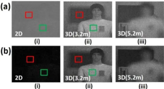
Fig. 3 shows the DoP images between the proposed approach and conventional 2D methods. Without reducing the camera offset, the 2D DoP [see Fig. 3a (i)], and 3D DoP [see Figs. 3a (ii) and (iii)] intensities are close to 0, DoP images cannot reveal the accurate polarimetric information of the scene. By removing the offset, the polarimetric images may contain zero or negative digitized intensity values, and the corresponding 2D DoP may be saturated (DoP >1 or <0) [see Fig. 3b(i)]. The 3D DoP image can mitigate the saturation effect; however, it is still noisy as shown in Figs. 3b (ii) and (iii). The total variation (TV) denoising algorithm [18] is further applied [see Figs. 3c (ii) and (iii)] to enhance the image quality.
Fig. 3. 2D and 3D DoP images, (a) with camera offset, (b) without camera offset, and (c) without camera offset and with total variation (TV) algorithm. (i) 2D DoP, (ii) 3D DoP at z = 3.2 meters, and (iii) 3D DoP at z = 5.2 meters. Yellow and red windows correspond to the polarimetric and non-polarimetric material areas [16].
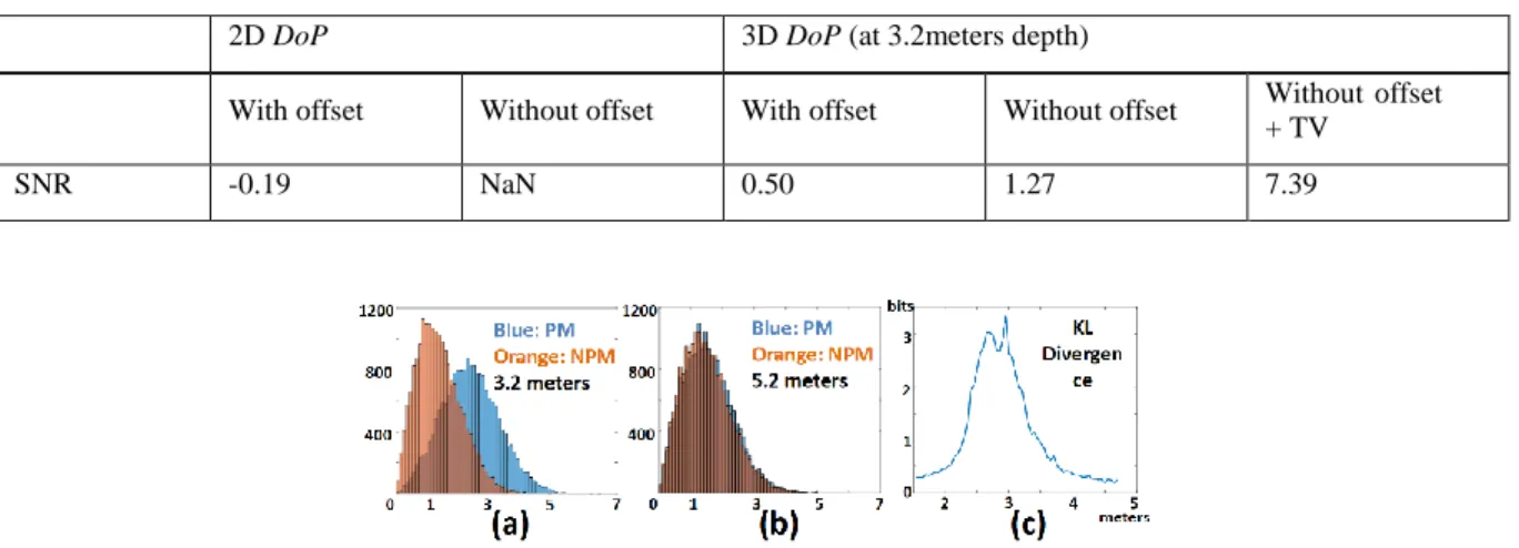
The SNR results are shown in Table 1. The SNR of the 2D DoP [see Fig. 3a(i)] is negative with a value of -0.19, and the saturated 2D DoP [see Fig. 3b(i)] provides a unreliable SNR value. The 3D DoP at 3.2 meters with offset [see Fig. 3a(ii)] and without offset [see Fig. 3b(ii)] have SNR values of 0.50 and 1.27, respectively. With the proposed approach, the SNR is 7.39 as [see Fig. 3c (ii)]. The histograms of the random variables derived from the 3D un-normalized DoP is illustrated in Figure 4(a)-(b) for depths of 3.2 meters and 5.2 meters, respectively. Fig. 4(c) depicts the KL Divergence curve between the polarimetric and non-polarimetric areas along the depth range.
Table 1. SNR of the DoP images for 2D and 3D polarimetric images with and without camera offset, and with TV algorithm. Estimated photons/pixel = 1.24 [16].
2D DoP 3D DoP (at 3.2meters depth)
With offset Without offset With offset Without offset Without offset + TV
SNR -0.19 NaN 0.50 1.27 7.39
Fig. 4. Histograms of un-normalized DoP [see Eq. 5] at (a) 3.2 meters focused on object, and (b) 5.2 meters (background). PM = polarimetric material, NPM = non-polarimetric material. Estimated photons/pixel = 1.24. Windows [see Fig. 3b(ii)] were selected on areas corresponding to the PM area (yellow box), and NPM area (red box). (c) Kullback-Leibler Divergence between the windows along depth range Z [16].
4. CONCLUSION
In this letter, we have demonstrated a previously reported approach for effectively extracting 3D polarimetric information under low illumination conditions. 3D Stokes polarization parameters are obtained by the integral imaging technology and the DoP images are calculated without the effect of camera offset. Total variation algorithm is further applied to enhance the DoP image quality. We also developed a statistical approach to analyze 3D polarimetric properties in the scene. Experimental results verified that the proposed approach can extract 3D polarimetric information in low light conditions, and it outperforms the 2D polarimetric imaging which performed poorly in these conditions.
REFERENCES
[1] Javidi, B., Shen, X., Markman, A.S., Latorre-Carmona, P., Martinez-Uso, A., Sotoca, J.M., Pla, F., Martinez-Corral, M., Saavedra, G., Huang, Y.P., Stern, A., "Multidimensional optical sensing and imaging system (MOSIS): from macroscales to microscales, " Proc. of the IEEE. 105(5), 850-875 (2017).
[2] Lippmann, G., "Epreuves reversibles donnant la sensation du relief," J. Phys. Theor. Appl., 7(1), 821-825 (1908). [3] Javidi, B., Okano, F., and Son, J. Y., Threedimensional imaging, Visualization, and Display, (Springer, 2009).
[4] Martínez-Corral, M., Javidi, B., "Fundamentals of 3D imaging and displays: A tutorial on integral imaging, light-field, and plenoptic systems," Advances in Optics and Photonics. 10(3), 512-66 (2018).
[5] Javidi, B., Ponce-Diaz, R., and Hong, S. H., "Three-dimensional recognition of occluded objects by using computational integral imaging," Opt. Lett. 31(8), 1106-1108 (2006).
[6] Stern, A., Aloni, D., and Javidi, B., "Experiments with three-dimensional integral under low light levels," IEEE Photonics J. 4(4), 1188-1195 (2012). [7] Markman, A., Shen, X., and Javidi, B., "Three-dimensional object visualization and detection in low light illumination using integral imaging,"
[8] Shen, X., Kim, H-S., Komatsu, S., Markman, A., and Javidi, B., "Spatial-temporal human gesture recognition under degraded conditions using three-dimensional integral imaging," Opt. Express 26(11), 13938-13951 (2018).
[9] M. Born, and E. Wolf. Principles of optics: electromagnetic theory of propagation, interference and diffraction of light. (Elsevier, 2013). [10] H. Chen and L. B. Wolff, "Polarization phase-based method for material classification in computer vision,” Int. J. Comput. Vis., 1, 73-83, (1998). [11] J. Scott Tyo, Dennis L. Goldstein, David B. Chenault, and Joseph A. Shaw, "Review of passive imaging polarimetry for remote sensing
applications," Appl. Opt. 45, 5453-5469 (2006)
[12] M. I. Mishchenko, Y. S. Yatskiv, V. K. Rosenbush, and G. Videen, Polarimetric Detection, Characterization and Remote Sensing. (Springer, 2011). [13] J.T. Murray, S. E. Moran, N. Roddier, R. Vercillo, R. Bridges, Austin W. Advanced 3D polarimetric flash ladar imaging through foliage. InLaser
Radar Technology and Applications VIII 2003 Aug 21 (Vol. 5086, pp. 84-96). International Society for Optics and Photonics.
[14] Xiao X, Javidi B, Saavedra G, Eismann M, Martinez-Corral M. Three-dimensional polarimetric computational integral imaging. Optics express. 2012 Jul 2;20(14):15481-8.
[15] Carnicer A, Javidi B. Polarimetric 3D integral imaging in photon-starved conditions. Optics express. 2015 Mar 9;23(5):6408-17.
[16] X. Shen, A. Carnicer, and B. Javidi, "Three-dimensional polarimetric integral imaging under low illumination conditions," Opt. Lett. 44, 3230-3233 (2019).
[17] J. S. Jang, and B. Javidi, "Three-dimensional synthetic aperture integral imaging," Optics letters 27(13), 1144-1146 (2002).
[18] L.I., Rudin, S., Osher, E., Fatemi, "Nonlinear total variation based noise removal algorithms," Physica D: Nonlinear Phenomena 60(1-4) 259-268 (1992).
![Figure 1. The previously presented integral imaging-based 3D polarimetric imaging. (a) 3D optical sensing, (b) computational reconstruction, and (c) polarimetric imaging [16]](https://thumb-eu.123doks.com/thumbv2/123dokorg/2972776.27513/3.918.285.639.822.1007/figure-previously-presented-integral-polarimetric-computational-reconstruction-polarimetric.webp)