Chapter 3
Hybrid Propulsion System
3.1 Introduction
A hybrid rocket [6] is a propulsion system that uses both a liquid and a solid as propellants. Although there are many components that are common to the liquid and the solid rocket, the operation of a hybrid is distinctly different. In the combustion chamber of solid and liquid rockets there is a “uniform” mixture of oxidizer and fuel, instead the hybrid burns as a macroscopic turbulent diffusion flame where the oxidizer-to-fuel ratio varies down the length of the chamber, ending at a composition that determines the motor performance.
There are many configurations of hybrid rockets. In the classical configuration the fuel is a solid and the oxidizer is a liquid. This is the most used and all the others are a variation of this design.
In the 1950s the reverse hybrids were evaluated, in which there is a solid oxidizer and a liquid fuel. A problem of this configuration is the difficulty of the solid oxidizer fabrication and moreover it has to be mixed either with inert filler or with a small percentage of fuel to press or mold the grains. This reduces the performance and it increases manufacturing risks.
Another configuration utilizes bipropellant combustion with a third component such as a metallised fuel. It usually uses an oxygen/hydrogen central core within either a cast beryllium-loaded polybutadiene (PB) fuel grain or pressed beryllium powder mixed with a small amount of Teflon as a binder. This propellant system has the highest known specific
impulse, a high combustion temperature (more than 5000 K) and also the presence of Be in the combustion zone that can avoid the problems of slurry with liquid hydrogen.
The last configuration is the solid-fuel ramjet that employs a solid fuel and ram air as the oxidizer. It has no liquid piping but the fuel has a low burning rate due to the oxygen dilution in the air. Nevertheless this deficiency can be avoided with the addition of a solid oxidizer to the fuel.
Figure 3.1: Currently project of Liquid Oxygen hybrid rocket in New Mexico test site.
3.2 Architecture
The classical configuration [7] considers a solid fuel with a liquid oxidizer. The advantage of the classical concept is that there are many solid fuels such as hydrocarbons and metals as well as a wide variety of liquid oxidizers such as oxygen, F2/O2 (FLOX), hydrogen peroxide, nitric acid, nitrogen tetroxide and nitrous oxide. The hybrid fuel is contained within the combustion chamber, and the oxidizer is fed from the oxidizer tank. The oxidizer is injected into a port in the solid grain subjected to heat transfer from the flame zone. The fuel grain in small hybrid rockets is generally the tube of combustible material [10]. The hole down to the center of the tube is called the fuel port. For larger hybrid rockets multi-port grain geometries are common in which there are several separate ports in the fuel grain, with oxidizer injected down each port. Single cylindrical port geometry provides higher volumetric efficiency for any high power or amateur rocket than multi-port geometry does. The disadvantage of this
type of configuration is that it requires generally long a length to diameter ratio compared to multi-port configuration. The multi-port configuration can be made short and compact, with length to diameter ratios of between three and seven.
In the following figure the configuration of a hybrid rocket can be seen (fig.3.2):
• Oxidizer tank (1)
- storage for liquid or gas
- typical materials are metals and wound fiber - lower pressure than pressurant gas
• Pressurant tank (2)
- pressurant gas maintains propellant tank pressure - typical gases are helium and nitrogen
- operates at pressure up to 50 MPa
• Pressure regulator (3)
- reduces pressurant pressure to desired propellant tank level
• Flow valve (4)
- controls the mass flow - can provide throttling
• Propellant grain (5)
- typically a hydrocarbon-based fuel
• Polar boss (6)
- transfers nozzle loads to motor case - provides nozzle/case interface
• Injector plate (7)
- feeds oxidizer into chamber - helps atomize propellant
• Port or bore (8)
- a motor can have any number of ports - port shape determines regression rate - typically cylinders and pie shapes
• Internal insulation(9)
- low thermal conductivity to reduce heat transfer to motor case - ablative material to dissipate heat
• Nozzle assembly (10)
- allows exhaust products to expand into ambient environment - key parameters are expansion ratio and cone angle
- thrust vector controls vary the effective nozzle geometry
- high temperature materials minimize heat and oxidation problems - typical materials are sintered graphite and silicon phenolic
Figure 3.2: Schematic of hybrid rocket
3.3 Advantages and Disadvantages.
The difference between a classical hybrid and the liquid or solid rocket leads to a number of distinguishing characteristics. The advantages are as follows [8], [6]:
It is based on the physical separation between the oxidizer and the fuel. The stored propellant components cannot be mixed due to their separate phases, the solid fuel grain is insensitive to cracks and imperfections, as solid monopropellant.
The manufacturing, the integration and the coactivity can be done in the same time and at the same place without any particular protection.
The operating point of hybrid motor does not depend on the pressure as solid rocket engines, ambient launch temperature variations have little effect on the operating chamber pressure thus it has a low temperature sensitivity (lower maximum combustion pressure).
• Shutdown and restart capability.
The thrust can be easily throttled or stopped by modulating the liquid flow rate, which is simpler than in a liquid rocket where two flow rates must be synchronized while being modulated. This improves the energy management.
In case of a problem measured during the operation, the engine is made inert by cutting off the oxidizer feeding and emptying the oxidizer tank. An auto destruction sequence is not necessarily required with this system and the payload could be recovered.
• Grain robustness.
Unlike solid rockets, fuel grain cracks are not catastrophic, because burning only occurs down the port where it encounters the oxidizer flow.
• Low cost.
Thanks to the reduction of critical components, the hybrid rocket is less expensive than a solid or liquid engine during development and launch preparation. Manufacturing of the fuel can be done in a commercial facility that does not require the large acreage and many buildings for solid propellant manufacture and the fuel plant can be situated at or near the launch site. The system can also tolerate larger design margins, resulting in a lower fabrication cost.
• Propellant versatility.
There is a wider choice of fuels. In contrast to liquids, it is possible adding solid constituents like energetic metals to enhance performance and density without
resorting to slurries; in contrast to solid, the liquid oxidizer provides higher energy levels.
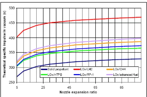
Figure 3.3: With advanced fuels, the Isp gain can be significant and equal to semi cryogenic propellants (Lox/CH4 for instance)
• Reduced ecological impact and payload pollution (Table 3.1).
Whatever the life phase the impact on the health and environment is minimum. The hybrid system does not use toxic or explosive material or propellant.
With classical components, a hybrid rocket doesn’t emit solid or liquid particles, which is profitable regarding the pollution of the payload.
Solid propellant
Hybrid propellant
CO 0,23841 0,34233 CO2 0,01518 0,21329 H2O 0,08831 0,22244 H2 0,34108 0,12748 N2 0,07699 0,00227 H 0,00056 0,00030 OH 0,00001 0,00005 HCl 0,15171 0,00000 Al2O3(s) 0,08755 0,00000 Cl 0,00019 0,00000
However the hybrid propulsion has also disadvantages such as:
• Low regression rate.
The low sensitivity of the solid fuel at the operating conditions and the low regression rate require large surfaces of regression and lead to lower volumetric loading efficiency. The small resulting fuel web means that most combustion chambers over a foot in diameter require multiple ports to provide adequate burning surface to meet the required thrust. Nevertheless, at the moment it is used for applications with a low thrust requirement like target drones, hovering vehicles and gas generators.
A consequence of the low regression rate and the presence of multi ports is a relatively low volumetric fuel loading or bulk density. The number of multiport dual grain also leads to a moderate amount of unburned fuel slivers.
• No fixed oxidizer/fuel ratio.
Mixture ratio is not fixed in hybrid engine, it varies in combustion chamber. The fuel mixture is rich over the fuel grain surface and lean in the core. The opening of the port during burning causes the shift of O/F ratio with burning time, which can lower the theoretical performance. A design which provides uniform and full burnout of fuel grain is an essential problem for hybrid rockets. However, with the proper design this loss is minimal, and ballistic calculations shows that it can be held to less than 1% for a classical hybrid.
• Blow-back.
Nitrous oxide tanks particularly have been known to blow-back and cause monopropellant deflagration (combustion instabilities are one of the main causes of this phenomenon, particularly towards the end of a burn when the tank pressure is low. Ensuring sufficient pressure drop across the injectors is necessary at all times).
• Performance.
The nature of the large diffusion flame results in a lower degree of mixing and a lower impulse efficiency. This loss is generally 1-2% greater than in either liquids or solids. However, it is theoretically possible to achieve a higher specific impulse
than for solid rockets (fig. 3.3) combining a high performance oxidizer like LOx with a polymer solid fuel. The liquid rocket counterpart raises fears about high costs, which are up to three times more per kg launch mass compared to the solids. Its higher performance (specific impulse, structural index) allows lighter booster, so that this can be partially compensated.
• Technology with smaller degree of maturity. The development of hybrid rocket engines is not as far as that of liquid and solid propulsion.
3.4 Hybrid rocket fuels
Hybrid propellants [9] should meet general requirements imposed upon chemical propellants and, consequently, include components that have the greatest initial density, provide the chemical interaction with the greatest heat release and yield combustion products with a possibly lesser molecular weight. Propellants based on polymer hydrocarbon fuels (synthetic rubbers) with liquid oxygen or concentrated hydrogen peroxide are most simple, highly mastered and, at the same time, efficient enough. For raising power characteristics and stabilization of combustion metals (or metal hydrides) can be added to solid components. These for example aluminium, boron and lithium. The process of grain burning is closely related to the technique of oxidizer supply to the combustion chamber and flow organization. It is necessary to regulate the oxidizer flow rate for maintaining optimum internal ballistic parameters and ensuring stable burning at a high completeness of combustion
The more common fuels include:
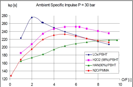
• Poly Methyl Methacrylate [(C6H10On)n ],( PMMA, Acrylic or Plexiglas). Poly Methyl Methacrylate has a density of 1683 kg/m3. Green propellant N2O/PMMA (fig. 3.4). N2O is self-pressurized at ambient temperature (60 bar). This type of propellant is very practical for experimental research. The Maximal Isp is 233s at a pressure of 30 bar.
• Polyethylene (PE). High Density Polyethylene (the most frequent form of Polyethylene used for hybrid rocket fuel) has a density of 960 kg/m3 and a heat conductivity of 0.23-0.29 Wm-1K-1.
• Poly Vinyl Chloride (PVC). PVC has a density of 1380 kg/m3 and the thermal conductivity of 0.16 Wm-1K-1.
• Paraffin (CnH2n+2). Paraffin is a mixture of higher alkanes. The density is 850-900 kg/m3.
• Hydroxyl terminated polybutadiene (HTPB). HTPB has a density of 930 kg/m3 and a thermal conductivity of 0.217 Wm-1K-1.
• BAMO Biazidomethyloxetane (binder).
Figure 3.4: Comparison of green propellant performance.
At the moment research for advanced fuel is in progress (see fig. 3.3), therefore some elements are defined arbitrarily with regard to some theoretical results with past studies like paraffin or mixed.
3.4.1 Hydroxyl terminated polybutadiene
Hydroxyl terminated polybutadiene [11] has been one of the most commonly used polymers in composite solid propellants (fig. 3.5). Its role in composite solid propellants is mainly two-fold: to serve as a binder material to physically accommodate different propellant ingredients (such as oxidizer, metal particles and burn-rate modifiers) and to serve as a fuel constituent to release fuel-rich gaseous products when decomposed and pyrolyzed.
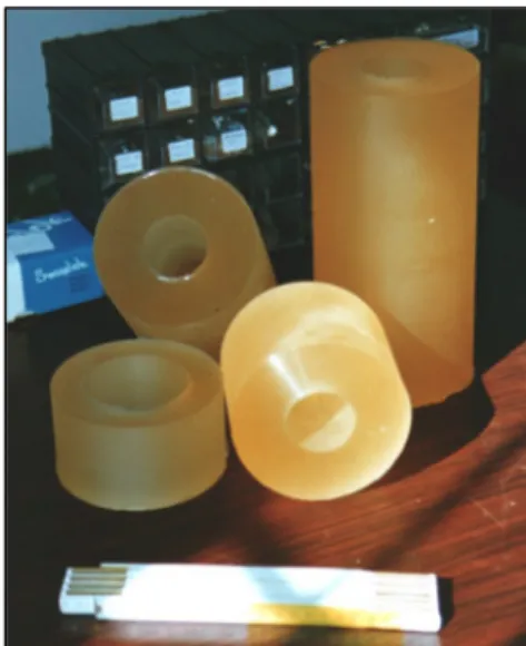
Figure 3.5: Solid grain of HTPB
In order to achieve good mechanical properties, HTPB is usually mixed with a diisocyanate crosslinking agent, and then cast into the desired grain configuration before it is completely cured (fig. 3.6). In a given motor configuration, each oxidizing additive has a critical concentration above, which sustained burning will persist. This critical concentration, is scale dependent, thus is not simple to use in large scale applications.
The most common additives for the HTPB are:
- HTPB + nano Tungsten (nW) - Hydrides additives
- HTPB + nano Aluminium (nAl) burning in gaseous Oxygen (GOX) - HTPB + Lithium (Li)
Recently, cured HTPB has also been considered one of the most promising solid fuels for application in hybrid propulsion systems because of its high heat of combustion when reacting with oxidizer (usually liquid oxygen or gaseous oxygen). The specific impulse
delivered by HTPB/GOX or HTPB/LOx system is comparable to that of solid and liquid propellants.
Figure 3.6: Specific impulse comparison between HTPB with different type of additives.
The HTPB- based solid fuel regresses with a low rate (typical 1 mm/s) compared to a solid propellant. The required large wetted fuel surface results in complex voluminous fuel grain geometry with many individual ports to achieve the required fuel flow, which results in a low volumetric loading.
3.4.2 Fuel residuals
Specifically, the solid fuel residual is an important issue of hybrids, but it is often overlooked or not reviewed carefully. Residuals can not be avoided due to the difficulties in predicting the O/F mixture ratio exactly, the complex geometry of many grains and the non-uniform fuel regression [12].
The solid rocket propellant contains premixed oxidizer and fuel components, so the O/F mixture ratio is fixed during the operation. In case of liquid propellant rockets, the flow of oxidizer and fuel can be calibrated with good results by orifices and valves. Residuals due to O/F mixture ratio shift are in range of 0.1 %. In case of the hybrid rocket motor, there are continuous changes of fuel regression range, O/F mixture ratio, chamber pressure and thrust
during operation, which can be predicted for an ideal motor configuration perfectly without additional residuals.
In the case of classical hybrid rocket only the oxidizer can be controlled directly. Therefore, the O/F mixture ratio of the flight unit has to be predicted with high accuracy in advance by design measures. However, insufficient design tools and unavoidable nominal tolerances in the manufacturing process necessitate an appropriate fuel reserve to accomplish the dedicated mission profile. Complicated grain geometries as a three row wagon wheel type are proposed to achieve higher fuel-loading density. However, structural grain instability of such multi-port grains and port to port burn through shall be prevented. The most effective way to reduce fuel residuals is a single or double port grain configuration, which increases the fuel regression rate. The regression can vary from channel to channel, caused by a non uniform contribution of the oxidizer mass flow to top each grain port. The uniformity of fuel regression depends on port internal flow and oxidizer spray characteristics, and it is likely to vary with grain length and in the circumferential direction. Due to this uneven regression, some points of the hybrid motor case insulation may be reached earlier than others by the hot port flow. The insulation thickness has to be adapted to exclude these hazards from the hybrid rocket motor case.
3.5 Hybrid rocket oxidizer
The oxidizer can be either a storable or a cryogenic liquid, depending on the specific impulse or other requirements of the application.
The more common oxidizers include:
• Liquid oxygen (LOx). LOx has a boiling point of -183 °C at 1 atm. The molecular weight is 32 and it has a density of 1141 kg/m3
• Nitrous oxide (N2O). Nitrous oxide has a boiling point of -89.5 °C at 1 atm, and it is normally maintained as a liquid at a pressure of 54 bars. The molecular weight is 44 and it has a density of 1222 kg/m3 at 20 °C. The critical pressure and temperature of N2O is 7.27 MPa and 36.6 °C
• Nitrogen tetroxide (N2O4). Nitrogen tetroxide has a boiling point of 21.2 °C at 1 atm. The molecular weight is 46.01 and it has a density of 1903 kg/m3 at 20 °C
• Hydrogen peroxide (H2O2).
• Nitric acid (HNO3)
• Hydroxyl ammonium nitrate (HAN)
• Hydrazinium nitroformate (HNF)
• Ammonium dinitramide (ADN)
For a given hybrid propellant combination the fuel volumetric loading depends on the required thrust to weight ratio and geometrical properties such as diameter and the L/D ratio of the motor case.
3.6 Internal ballistics
Much of the technology from liquid and solid propellant rockets is directly applicable to hybrid rockets, the main difference is the internal ballistics [13].
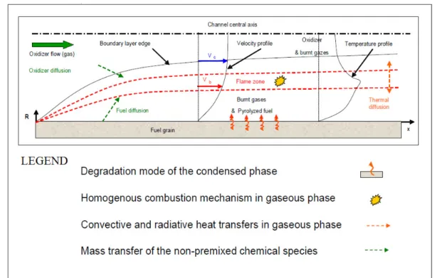
The combustion cycle is a self sustaining mechanism. The start of the combustion process happens with the ignition and the thermal degradation of fuel grain, and then there is a heat transfer because of the combination of convection and radiation processes from the diffusion flame to the fuel grain. The fuel degradation goes on with the regression of the fuel grain and the fuel blowing. Both the oxidizer and the fuel diffuse into the boundary layer towards the flame zone where the reaction take place in a thin diffusion flame. The combustion heat released in the channel goes to add to the heat transfer process. The regression rate is controlled by heat and mass transfer. These coupled phenomena are shown in the fig. 3.7.
Figure 3.7: Scheme of hybrid combustion
3.6.1 Regression rate
Solid fuel regression rate is the fundamental parameter needed for modelling the hybrid internal ballistics. Even though hybrids have been known since the 1930s, the regression process is still far from being completely modelled and the performance prediction has usually been based on simplified methods and correlations.
The solid propellant regression rate or burning rate has many variables and is primarily a function of pressure, temperature, grain composition, grain configuration, liquid oxidizer mass flow rate and the oxidizer injection system. With a single oxidizer spray injection location, the mixture of the fuel and oxidizer component along the length of the grain is not uniform and efficient combustion is difficult to attain. Obviously the selection of ingredients and the design of fuel grain have a significant impact on the grain regression rate, which is largely a function of the sublimation temperature, heat of depolymerisation, and the latent heat of sublimation; these three are equal to the total heat of gasification of the fuel.
Most analytical models of combustion in the hybrid rocket assume that the chemical reaction between fuel and oxidizer occurs in the turbulent boundary layer near the grain surface and not as combustion near the center of the fuel grain perforation.
- turbulent flow
- negligible pressure gradient
- negligible radiation and conduction in the fuel
From the energy balance of the fuel surface (fig. 3.8):
(
fl s)
e h c p frh q C G h h ρ & = & ≅ − (3.1) wherehp is the heat of pyrolysis of the fuel and Tfl, Tsare respectively flameand fuel surface temperatures.
Obtain the blowing coefficient:
const h ∆h C G r ρ B p h e f ≅ = = & (3.2) where
Ge=ρeue is the mass flow rate per unit area
The regression rate distribution is calculated in a zone that is supposed to be nearly the uniform port area A and the uniform port perimeter P. Look the example in the table 3.2. In the classical hybrid configuration the combustion process is limitated by diffusion thus the regression rate is often assumed to be only mass flux dependent according to the semi-empirical equation (3.4).
Considering the oxidizer flow rate m&0 = ρ0u0A at distance x from the port entrance:
∫
+ ≅ x f e ρ r P dx A G G 0 0 1 & (3.3) and m n e x aG r =& (3.4)Thus the local regression rate is:
∫
− − + + − + = = x n n n m f m n ) u m)A(ρ ( Pax n)ρ ( x aG dx r dx d r 0 1 1 0 0 1 0 1 1 1 & & (3.5)in which the constant a is considered linked to the propellant system and the exponent n is generally variable between 0.6 and 0.8.
The regression rate behaviour depends strongly on the particular port size as well as grain length-to-diameter ratio and can change significantly with burning time. This makes it likely that both a and n would vary with the specific port geometry, the firing duration, and the mass flux itself. This regression rate mass flux dimensional correlation is inappropriate for the purpose of scaling to motors having different dimensions and/or other propellant combinations. However, even considering the same propellant and characteristic dimensions, the application of this relation to other motors can lead to considerable disagreements between the expected and the measured regression rates, and one reason is certainly represented by oxidizer injection effects whereby the boundary layer can be disturbed.
x (m)
t = 0.1 sec t = 20 sec t = 60 sec Port Dia. (m) r& (cm/s) O/F Port Dia. (m) r& (cm/s) O/F Port Dia. (m) r& (cm/s) O/F 0.381 0.152 0.263 17.19 0.227 0.143 21.34 0.315 0.087 24.11 0.762 0.152 0.231 9.102 0.220 0.131 11.40 0.301 0.081 13.20 1.143 0.152 0.221 6.316 0.217 0.127 7.983 0.296 0.078 9.640 1.524 0.152 0.217 4.835 0.216 0.125 6.139 0.293 0.077 7.249 1.905 0.152 0.215 3.917 0.215 0.123 4.974 0.292 0.076 6.006 2.286 0.152 0.215 3.310 0.215 0.123 4.177 0.291 0.076 4.972 2.667 0.152 0.215 2.852 0.215 0.123 3.594 0.291 0.076 4.342 3.048 0.152 0.216 2.506 0.215 0.123 3.115 0.291 0.075 3.757 3.429 0.152 0.218 2.234 0.216 0.123 2.771 0.291 0.075 3.375 3.810 0.152 0.219 2.016 0.216 0.123 2.495 0.292 0.075 3.008 4.191 0.152 0.221 1.831 0.216 0.124 2.263 0.292 0.075 2.747 4.572 0.152 0.224 1.677 0.217 0.124 2.073 0.293 0.076 2.492
Table 3.2: Burning rate contours in a circular port. (n=0.75, m=0.15, oxidizer mass flow=7.95 kg/s, a=2.066*10-5, fuel density=1000 kg/m3)
3.6.1.1 High regression rates
To generate a high regression rate, three different methods are used at the moment:
• Energetic fuel additives.
In 1960s one started to use ammonium perchlorate (NH4ClO4 or AP) and ammonium nitrate (NH4NO3 or AN) to improve the performance. More recently other energetic additives as nitro organic compounds, RDX (CH2N2O2)3 and HMX (CH2N2O2)4 have been added to the conventional PB to lower the heat of vaporization by generating an exothermic reaction in the vicinity of the propellant surface.
As already mentioned, each additive has a critical concentration above which shutoff is not possible.
• Turbulent generators.
To increase the heat transfer coefficient, high degrees of turbulence are generated at the burning surface. An early design was based on inserting wire screens periodically in the grain normal to the axis. During burning, the ragged edges of the screens acted as turbulence trippers, and an increased overall burn rate was observed. Other techniques were also explored. One is adding an easily vaporized component that on vaporization creates vacuoles to roughen the surface [14] and another is the
generation of a vortex in a circular fuel port, driven by the tangential injection of oxidizer [15].
• Liquid entrainment.
When liquid entrainment occurs, the resulting propellant flow from the surface is composed of a mixture of vapour and liquid droplets. This occurrence can have a profound effect on the regression rate. This method is very effective, because the droplets that are formed do not require heat of vaporization, but only heat of fusion and moreover the gas flow from the surface is reduced, the blowing term B is diminished, resulting in a reduced blocking of the convective heat transfer.
3.6.1.2 Influence of dimension of port diameter
Much research has been done on the influence of the internal port diameter [16]. Recent test showed that at the same mass flux, with higher average port diameter, higher fuel regression is obtained. This is a consequence of the wider recirculation region which can be established inside the port with larger diameters. Moreover an exponent of the power law in the equation (3.4) close to 0.55 has been found. This appears to be in contrast with previous investigations on that subject and certainly with the chamber pressure-time trace versus time measured in that test campaign. Pressure increases all over the tests with the axial injector and, the oxygen mass flow rate increases as well. Thus, because the spatially average
regression rate decreases with the port diameter enlargement, this implies the regression rate dependence on the mass flux with an exponent less than 0.5. However, in previous studies an exponent close to 0.4 was found with polyethylene fuel and oxygen. The main difference between this investigation and the previous one lies in the range of grain inner diameters.
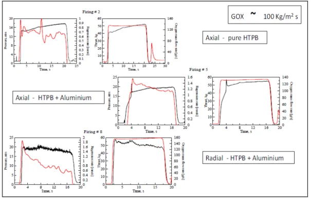
3.6.1.3 Influence of aluminium additives on the regression rate
The research regarding the addition of aluminium particles has given three important results shown in the fig 3.9. The first of these shows that with the axial injector no appreciable effect can be unveiled, because the measured regression rate levels are exactly the same, while with the radial injector and HTPB addicted with aluminium, the regression rate obtained was still lower than the one achieved with the axial injector. Furthermore, based on
the regression rate prediction without aluminium, it seems that at high mass flux a significant increase of regression rate could be expected, but the data available are not enough to derive any definitive conclusions.
Figure 3.9: Effect of the aluminium particles addiction on the regression rate
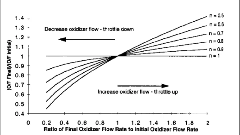
3.6.2 Oxidizer to fuel ratio and grain length
The oxidizer to fuel ratio varies along the length of the fuel grain.
This behaviour is completely different compared with solid and liquid rockets. In a liquid rocket, the injector generally injects both the fuel and the oxidizer at one end of the combustion chamber thus there is no axial dependency instead in a solid rocket there is no injection head, and every particle is bound by fuel and oxidizer, thus ensuring the O/F remains almost constant.
The oxidizer to fuel ratio is given by:
1 2 1 0 1 1 0 0 1 − − + − ≈ + = = m n Hn f n f A f o D m Pax ρ m)A ( A m Px r ρ G m m & & & & & (3.6)
m n H n ) /(m st f f n st m D ) m / m Pa( ρ /A) m m)A( ( L + − − + − ≈ + = 1 1 2 1 0 1 1 0 1 0 1 & & & & (3.7)
Both the oxidizer to fuel ratio and the stoichiometric length vary with the throttling(m&0), except for n=1 and with the web burnt (DH), except for n=0.5 (fig. 3.10)
Figure 3.10: Graphic that shows the variation of the O/F in function of the oxidizer flow rate.
3.6.3 Chamber pressure
The chamber pressure is one of the most important parameters. From the mass continuity for the thrust chamber with ρ =c pc/RTc and dVc/dt =Abr& :
f c * t c m n b c c c * t c f c c p m m c A m)RT ( L aG A dt dp RT V c A p m m ) V (ρ dt d & & & & + = + + + + ⇒ − + = 0 0 0 1 (3.8)
Thus, in quasi-steady conditions:
0 ≅ dt dpc ⇒ + ≅ + + + = 0 0 0 0 1 1 m m A m c c A m)RT ( L aG A m m p f t * * t c m n b f c & & & & & (3.9)
and in the unsteady case, integrating with pc=pc0 at t=0:
λt c c c c p (p p )e p − = 0 − − where: * c c t * c t m n b c V c rT A c RT A m) ( L aG A V λ ≅ + + = 1 1 0 (3.10)
Hence the chamber pressure pc is always stable.
3.7 Combustion chamber
The combustion chamber not only provides the location for propellant combustion, but also contains the whole fuel grain. The length of the combustion chamber is determined by the fuel grain configuration (i.e. a single port or multi port fuel grain configuration). Also, a longer combustion chamber means a more stable combustion, since the propellant has more time for mixing.
Injection into a pre-combustion chamber is more useful for larger hybrid rockets where a multi-port geometry is used for the fuel grain, since multiple injectors are more common, and even the mixing of the oxidizer stream needs to be achieved before it is passed over the fuel grain.
Post-combustion chambers are used to enable more complete burning of the propellants before the combustion products are expelled through the nozzle throat. Post-combustion chambers are less widely used than the pre-combustion chambers since they can cause quite severe erosion of the combustion chamber in the region of the post-combustion chamber and the benefit of using it can often be outweighed by the increased mass of insulation necessary to prevent burn-through of the post-combustion chamber. However a post mixing is used to increase the combustion efficiency typically from 60-80% to 95%
3.8 Injection system
Oxidizer injection effects on the fuel regression rate are one of the most important aspects of the hybrid combustor design. Hence there is a real need to study the injector influence on the combustor thermofluid dynamics to develop reliable tools for the prediction of regression rate under different flow conditions.
If the oxidizer is fed into the fuel port by a conical axial nozzle, the recirculation region, established between the gaseous oxidizer jet boundary and the fuel grain’s surface upstream of the impingement region, induces a convective heat flux to the fuel wall, which is higher and differently distributed when compared to the one in the turbulent flow through straight constant-cross-section pipes [17]. Rather, the flow field and the ensuing heat-transfer distribution in this condition are almost similar to those in a solid fuel ramjet having a sudden
expansion of airflow. In fact, in both axial injector hybrid motors and solid fuel ramjets, three distinct flow regions exist (fig. 3.11):
Figure 3.11: Axial injection hybrid rocket with the main flow characteristics.
The first region is the recirculation zone, into which oxygen is transported from the jet core across the turbulent shear layer (here, fuel provided from the wall is recirculated and reacts with oxygen near the head end of the grain; the flame initiates along the shear layer). The second region is the impingement or reattachment region where the oxygen attacks the grain surface; and the third region is the zone downstream of oxidizer impingement, where the turbulent boundary layer starts developing. Within this boundary layer a diffusion flame is formed.
This injection technique result in regression rates both increased (up to 2.5 times higher) and more or less unevenly distributed along the axis, depending on the ratio between the grain final diameter and the injector diameter. Furthermore, this flow field leads to a lower dependence of regression rate on mass flux and introduces a pure geometric effect, which is an explicit regression-rate dependence on the grain port diameter.
Besides the enhanced regression rate, the axial injector deserves careful attention because of its easy design and the remarkable feature that it is supposed to produce a stable combustion with no substantial pressure oscillations owing to the hot gas recirculation zone established within the combustion port.
When the radial injector cup, shown in fig. 3.12, is assembled on the injection flange, it produces a high speed radial flow of oxidizer via equally spaced orifices around the periphery
of the cup. This injection technique prevents the high recirculation that is yielded by the axial injector. More precisely, in both configurations a large vortex ring should be produced, but for the radial injector this vortex should stand apart from the fuel grain forward face, whereas for the axial injector the vortex can extend well into the combustion port.
Figure 3.12: Axial/radial injector and dump plenum at the head end of the motor
Many considerations have been made about the influence of the injection way on the regression rate by Carmicino and Russo Sorge at the University of Naples. They noted that with the axial injector motor, at the same mass flux and pressure, the efficiency is higher than the corresponding one obtained with the radial injector. This is believed to be because of a more efficient mixing of propellants in the recirculation region.
When the axial injector is used, depending on the ratio between the average port diameter and the injector diameter, a concave diameter profile along the axial abscissa has been measured; i.e. the larger the ratio, the larger is the non-uniformity of fuel consumption which shows a broad maximum in the region of jet impingement. The latter is, of course, a consequence of the heat flux distribution.
Tests performed with the axial injector have not shown any significant pressure oscillations, while tests with the radial injectors and HTPB with aluminium particles displayed rough combustion with pressure oscillations whose peak-to-peak amplitude reached 20% of the average pressure.
Figure 3.13: Results obtained in 2008 in the frame of ESA TRP hybrid program
3.9 Thermal protective material in hybrid rocket engine
One of the ways [9] to essentially raise power-and-mass characteristics of hybrid rocket engines (HRE) is the application of composite materials for manufacturing the combustion chamber and nozzle units. In doing so, designs and technologies widely approved during the designing and finishing development of solid rocket motors (SRMs) can be used successfully. However, it should be considered, that the operating conditions of thermal protective materials in HRE differ from those in SRM. At comparable heat fluxes, temperatures and loads, the distinctive feature of HRE operating conditions is a high concentration of oxygen-containing combustion products. So, to provide nozzle operability and minimization of ablations of thermal protection, enhanced requirements for oxidizing resistance of the latter are necessary. To satisfy these requirements, along with conventional carbon-graphite composite materials and carbon-phenolics, carbon-ceramics composite materials, including siliconized ones, as well as various methods of active thermal protection are considered for the use in HRE.
For the determination of resistance and ablation rate of composite materials in oxidizer flows, design and experimental investigations were carried out, fire tests of various material samples were conducted for subscale HRE too. Test results allow for achieving a more precise definition of mechanisms of the interaction between oxidizer flows and materials of different
structure and composition, determination of necessary empiric constants describing physical and chemical processes at surface and within composite materials. Among these are the constants of the Arrhenius law and the constant of reaction order that describes kinetics of endothermic oxidation of carbon frame and carbon or carbide matrix of material, heat effects of reactions or phase transitions, including formation and destruction (evaporation) of oxide films arising with heating of carbon-ceramics materials.
At relatively moderate operating times of HRE (up to 100 s), as thermal-protective coatings, carbon-carbon composite materials may be used for coatings in the region of throat sections, carbon- and glass-phenolics for nozzles of large area expansion ratios. For HRE at a long term or cyclic operation, carbon-ceramic composite materials can be recommended.
If stringent requirements are placed upon stability of HRE passage sections and nozzle contour, active methods of thermal protection, including those on the basis of low-temperature films out of neutral or weakly acid products of decomposition of dual-propellant grains may be considered as alternative. At a consumption of decomposition products equal to 0.5 . . . 1.5% of engine total consumption in terms of their afterburning in the near-wall layer, a decrease in the oxidizing potential of combustion products by a factor of three to five and in an equilibrium wall temperature at the throat section region by 300 to 500 K is possible. Both factors allow it to essentially reduce the ablation rate of carbon-graphite materials from 0.1 . .
. 0.2 mm/s (with the absence of film) down to 0.01 . . . 0.015 mm/s. A certain increase in specific impulse losses, conditioned by the influence of film, is fully compensated for the absence of losses by erosion of the nozzle throat and an associated decrease in the effective area expansion ratio. For nozzles of large area expansion ratio, the losses by film are less by a factor of three to five than losses by nozzle contour distortion.
3.10 Past hybrid booster activities
There are only few experiences with larger hybrid rockets [12]. Serious activities concerning the application of the hybrid rocket for space launch stated with foundation of the American Rocket Company (AMROC). This company conducted several hundred hybrid rocket firing tests during 1985 and 1993 up to the so called H-1800, which had a trust level of 1100 kN. A first development version DM-1 was tested four times. The H-1800 was foreseen to propel the sounding rocket HyFlyer with ~40 tons launch mass [18] and the small 4-stage
launch vehicle Aquila [19]. Some subsystem hardware (i.e. hybrid rocket motor DM1, LOx tank, heated helium pressurization system) was built, but not fully qualified for space launch.
However, these projects were scrapped before a rocket was launched or even completed, because AMROC filed for bankruptcy in August 1995 after spending of ~25 106 $ private investor money. In 1998 Space Dev obtained AMOROC´s technical rights and supplied the Space Ship One hybrid propulsion (fig. 3.14) and proposed a booster for its Streaker vehicle on the base of the H-1800/HyFlyer technology.
Figure 3.14: The suborbital launcher Space Ship One; build by Scaled Composites with composites materials, uses hybrid rocket made by Space Dev. First flight of commercial space vehicle at maximum altitude of 112 Km on June 21st 2004
Another major achievement sparked by AMOROC´s work was the Hybrid Propulsion Demonstration Program (HPDP), supported by a consortium of industry, DARPA and NASA. The HPDP consortium and its pre-existing JIRAD consortium achieved significant subscale testing results. Two examples of hybrid rocket motor 250-K, similar in size and performance to the H-1800 motor, were tested four times between 1999 and 2002 by HPDP. Besides other problems, the tests did not achieve the target performance objectives, because the fuel regression was underestimated and in addition, low frequencies instabilities with very high pressure excitations occurred.
Lockheed Martin Cooperation took the guiding role in the field of hybrid rocket activities of HPDP. In 1997, the company proposed the 250-K motor for application as a strap-on booster for the Atlas IIAR at the time, when only HPDP subscale test data were available. Caused by fundamental development problems the booster proposal was not realized at the end.
Together with Lockheed Martin, NASA MSFC started the development of the HYPR sounding rocket some years later; one of the largest, hybrid rockets (270 kN thrust, 31 s burning time, 31 s burning time, 2 ft diameter) that was ever launched. However, the mission of December 2002 missed their apogee target, due to hybrid rocket grain difficulties and the launch remained a single event. Nevertheless, a new helium heating system for the pressure fed hybrid rocket based on small hybrid fuel grain was applied for the first time. Recent activities of Lockheed Martin were the demonstration of the hybrid rocket propulsion with 105 kN thrust and a burning time of 170 s for the second stage of a small launch vehicle in 2005.
The year 2008 was a historical year because the world governments’ expenditures for space programs were at historical record, estimated at more than $62 109. The driving growths were both civil and defence-related programs.
The civil space programs are driven by [19]: - satellite communication and navigation - the boom of the observation of the world
- the space exploration (manned spaceflight and space science) - sustained investment in launcher development
- the multiplication of satnav and satcom projects - space science
Besides the national or transnational agencies that define the different space systems, for the past few years some private companies have tried the adventure of space proposing some operational applications. Among the numerous offers, the following space applications can be highlighted:
- sounding rockets for university experiments or little meteo tests
- space tourism (Space Ship One has demonstrated the possibility of launching some few people on a suborbital flight)
- low-cost small launchers in order to put into orbit small satellites (< 500 kg) – Falcon1 launcher is an example of such a proposal,
- low-cost medium launchers at term with the Falcon 9 type launcher (to be demonstrated in flight)
Otherwise, some reusable systems only used for LEO orbit (to serve the ISS for instance) can be imagined allowing to reduce the cost of a launch. As these systems are proposed by
private entities, the return of investments is one of the main requirements, which implies the reduction of development time, recurrent and non recurrent costs of each part of the launcher. Responsive space is also a strategic axis of new launchers development because it implies a new way of thinking with regard to launchers complexity and costs. Another application able to be proposed by a private company could be the orbital cleaning.