37
4 EXPERIMENTAL RESULTS
The setup of the original BRP engine and the first experimental studies has been performed by Matthew Labaza for his master degree thesis at University of Wisconsin-Madison. More detail about his work can be found in his thesis [25].
4.1 EXPERIMENTAL SETUP
The original BRP engine is a two-stroke, two-cylinder outboard recreational marine engine, produced by BRP under the Evinrude E-TEC product line. Its features are reassumed in Table 4-1.
Engine type Two-stroke, crankcase-scavenged intake design, Spark Ignited, Direct-injected
two cylinder in-line,
Power About 60 hp at 5750 RPM
Bore 91.47 mm
Conrod length 134.95 mm
Stroke 65.74 mm
Displacement 432 cc per cylinder
Compression ratio (geom/effect) 11.1 / 6.1
Boost port timing 122° bTDC /aTDC
Transfer port timing 120° bTDC/aTDC
Exhaust port timing 90 bTDC/aTDC
Oiling system Crankcase-injected, lost-oil
38
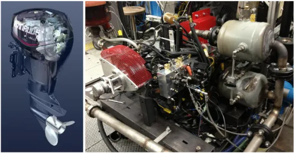
The engine employs a cross-scavenged scavenging flow using 4 ports: three scavenging ports and one exhaust port. The fuel is direct injected using a GDI E-Tec injector and the combustion is initiated by the spark plug. Figure 4.1 shows the original engine on the left and the engine mounted at the experimental bench in the laboratory of the ERC.
Figure 4.1 - The original engine and the experimental mounting assembly
Several modifications have been made on the engine to allow the use of RCCI concept with dual fuel direct-injection in one of the two cylinders. A new cylinder head has been designed, with a cylinder converted for RCCI operation while the other one allows using the production head to maintain the original SI operation and so the possibility to made comparison between the two has been maintained.
The RCCI cylinder head featured a removable plug in which the two injectors take place, one for the high-reactivity fuel and one for the low-reactivity fuel. Furthermore increasing or decreasing the thickness of the spacer between the head and the injector insert it is possible to change the compression ratio of the RCCI cylinder (Figure 4.2). The geometric compression ratio can be changed from a value of about 10 until a maximum of 16, reducing the volume in the chamber at the top dead center. Also the piston has been modified: the stock piston featured a little bowl which is targeted by the gasoline spray to concentrate the fuel near the spark plug allowing stratified charge operations (at low load). As is possible to notice in Figure 4.2, this feature has been removed in the RCCI cylinder.
39
Figure 4.2 - RCCI head and most its most important feature, from [25]
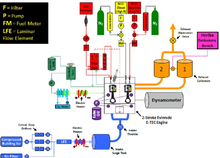
In Figure 4.3 the experimental setup of the engine is illustrated. In blue the air supply system is shown. There are two ways to supply air to the engine, from room air, passing through a filter, or using controlled compressed air. This second approach is usually the used one, because it allows better control on the characteristics of the intake air. The air passes through critical flow orifices where the mass flow of air is precisely measured. Than a large heater is used to control also the temperature of the intake air. The throttle valve has been maintained, to run the SI engine but also to add control on the internal EGR in the RCCI cylinder. In orange is illustrated the exhaust system is illustrated, which features separate exhaust pipe for the two cylinder to allow separate measurement of emissions produced by the two cylinder. The Horiba Emissions Bench samples the exhaust gas from the two exhaust collector to measure the emissions. A three way valve allows to select what cylinder emission has to be sampled. In the upper part the fuel system of both the engine is shown. For SI cylinder the fuel is pumped though the filter by the lift pump, operated from the crankcase. Then a high pressure pump delivers the fuel to the stock E-TEC injector. For RCCI cylinder each fuel is pumped into an accumulator, through a filter, by a lift pump. Than each accumulator is pressurized to the desired pressure using two separated nitrogen supplies. The injector used are the Bosh HDEV 5.2 for the low reactivity fuel, and a Delphi low-flow Microtec for the high reactivity fuel which are both derived from gasoline direct injected application (GDI).
High Reactivity injector Low Reactivity injector
Removable Plug
Adjustable CR with spacer thickness
40
Figure 4.3 - Schematic of the experimental set-up
4.2 RESULTS
Nowadays RCCI combustion on this engine was demonstrated at low-load low-speed condition (around 2 bar IMEP and 1550 RPM) using for high- and low- reactivity fuel diesel and gasoline respectively. Varying gasoline and injection timings at a fixed total fuel quantity was shown to change the phasing of the combustion and the performance of the engine in terms of efficiency and pollutant emission.
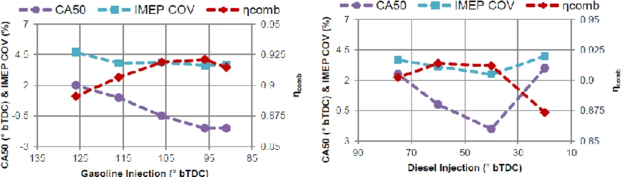
In Figure 4.4the result of the sweep of the injection timing of gasoline is shown on the left, maintaining fixed the diesel injection timing. The sweep of the injection timing of diesel is conversely shown on the right. Both of them at 1.5 bar IMEP and 1550 RPM. The diesel mass is 43% of the total
41
and the delivery ratio is 0.30, with an estimated EGR content of 53%.
Figure 4.4 - Results for Gasoline and Diesel start of injection, at 1.25 bar IMEP, 1550 RPM, delivery ratio 0.25 and diesel percentage of 43%
For gasoline injection timings the findings are:
timings earlier than 126° bTDC resulted in reduced combustion efficiency, possibly due to possible short-circuiting of charge and so an increases of UHC, this increase has been measured in the emission bench too
later injection timing causes earlier combustion phasing, the lack of mixing of the gasoline throughout the chamber probably cause the formation of more gasoline-rich and diesel-rich regions, where the latter initiates the combustion earlier
For the sweep of the diesel start of injection has been found:
timings earlier than 75° bTDC and later than 20° bTDC resulted in a loss of combustion because over-mixing and under-mixing respectively, probably with poor diesel mixing time the gasoline has difficulties to burns completely
the combustion phasing has not the monotonic behavior seen in the sweep of the gasoline start of injection. The earlier combustion phasing occurs when the diesel SOI is at 40° bTDC. Retarding the injection to 20° bTDC the CA50 shift later of about 5 CA. This means that the combustion phasing is retarded but the ignition delay between the injection and the combustion is reduced because of the less mixing of diesel, and the formation of high reactivity pocket. If the diesel injection is anticipated the combustion phasing is retarded. This is consistent with the consideration that less mixing of the fuel cause anticipated
42
combustion because of the increased maximum local reactivity
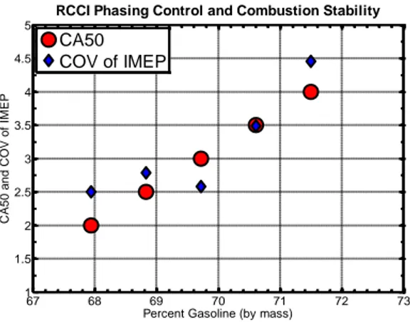
Varying the percentage of gasoline and diesel at a fixed total fuel mass affects the combustion phasing too, with a reduced slope with respect to previous study on RCCI but always linearly with a slope of about 0.5 CA50/%gasoline .
Figure 4.5 - RCCI phasing control and combustion stability with the variation of gasoline percentage
Comparison between RCCI and spark-ignited stratified combustion at idle condition has been made, showing similar emission levels. At increased load (2.0 bar IMEP) it has been found that varying the injection strategy it is possible to reach similar performance of the idle condition. Comparison between SI stratified and SI premixed shows RCCI had lower NOx emissions, while maintaining similar HC and CO emissions to the stratified case. Possible sources of CO and UHC formation for RCCI cylinder are the crevice area due to the piston ring, but also the crevice which is formed by the removable plug where are placed the injector. Indeed when this device is used to increase the compression ratio, protrudes inside the chamber, generating a crevice between this and the head. At 2.0 bar IMEP was established an indicated thermal efficiency of 35% and a calculated combustion efficiency of 91%. The maximum pressure rise rate (PRR) was below 3.25 bar/CAD (normally the limit value is about 10 bar/CAD). Also the coefficient of variation (COV), which measures the cycle-to-cycle variability, has been maintained below the 5% value, indicated by BRP as a limit value.
The possibility to use the thermal content of the residual gas to help the initiation of combustion has been also demonstrated. To do this, as aforesaid the throttle has been maintained,
67 68 69 70 71 72 73 1 1.5 2 2.5 3 3.5 4 4.5 5
Percent Gasoline (by mass)
C A50 and C OV of I M EP
RCCI Phasing Control and Combustion Stability
CA50 COV of IMEP
43
also if usually RCCI combustion does not need this device to control the load. Throttling the intake, reducing the scavenging efficiency and so increasing internal EGR, it has been found that the combustion phasing advances, due to the higher initial temperature of the trapped mass.
![Figure 4.2 - RCCI head and most its most important feature, from [25]](https://thumb-eu.123doks.com/thumbv2/123dokorg/7649490.119123/3.918.170.750.123.448/figure-rcci-head-important-feature.webp)