Research Article
FEM Simulation of Subintimal Angioplasty for the Treatment of
Chronic Total Occlusions
A. Avanzini
and D. Battini
Universit`a degli Studi di Brescia, Dipartimento di Ingegneria Meccanica e Industriale, Via Branze 38, 25123 Brescia, Italy
Correspondence should be addressed to A. Avanzini; [email protected]
Received 27 September 2018; Revised 7 December 2018; Accepted 18 December 2018; Published 31 December 2018 Academic Editor: Michalis Xenos
Copyright © 2018 A. Avanzini and D. Battini. This is an open access article distributed under the Creative Commons Attribution License, which permits unrestricted use, distribution, and reproduction in any medium, provided the original work is properly cited.
Subintimal angioplasty is a highly challenging technique for percutaneous treatment of chronic total occlusion (CTO) in blood vessels, and the development of predictive tools for preliminary evaluation of potential outcomes and risks could be very useful for clinicians. While finite element (FE) simulation is a well-established approach to investigating partial occlusions, its extension to CTO has not been investigated yet, because of several additional issues that have to be addressed. In this work, we discuss the implementation of a FE model to simulate the main steps of the procedure, i.e., subintimal insertion of an initially folded balloon in a false lumen, inflation from eccentric position, deflation, and extraction. The model includes key morphological features of the CTO and possibility of varying spatial distribution of material properties to account for different constituents and degree of calcification. Both homogeneous and heterogeneous CTO configurations were analyzed, comparing arterial stress state, plaque compression, and postprocedural recoil. For a peak inflation pressure of 12 bar, the degree of lumen restoration was in the range 65-80%, depending on plaque heterogeneity. After balloon extraction, homogeneous highly calcified plaques exhibited substantial recovery of original shape. For homogeneous and heterogeneous CTO, values of peak von Mises stress in the arterial wall were of the same order of magnitude (range 1-1.1 MPa) but at different locations. Results compared favorably with data reported in literature for postprocedural lumen restoration and arterial stress data, confirming potential usefulness of the approach.
1. Introduction
Progressive development of stenosis in a diseased artery may lead to a complete blockage of the vessel, known as chronic total occlusion (CTO). Due to the complete obstruction of the artery, percutaneous revascularization is difficult, because before placing and inflating an angioplasty balloon, a path has to be created for the catheter to go through the occlusion. To this aim, various techniques were developed, which could be broadly classified, depending on the working space, as intraluminal or extraluminal [1]. Here, we focused on extraluminal techniques [2], which consist in bypassing the site of the occlusion via a subintimal course, as schematically represented in Figure 1, creating an eccentric false lumen in which the angioplasty balloon is inflated. Subintimal angioplasty represents a technical challenge requiring great operator skill. The main potential risks include arterial damage or perforation, local dissection of the intima from
the media, barotraumas, and presence of a quite eccentric postdilation arterial lumen [3].
Numerical simulations may potentially help the physician to get additional information on feasibility of the procedure and its possible outcomes and risks, as a function of plaque characteristics. Design and optimization of dedicated devices and usage procedure would also benefit from realistic simu-lations of the technique. Indeed, there is a vast literature on the application of advanced approaches like computational fluid dynamics (CFD), finite element method (FEM), or fluid-structure interaction (FSI) analysis to study different types of cardiovascular diseases. In particular, FEM has been successfully adopted for investigations on interactions between balloon and stent, plaques, or arterial walls in the context of percutaneous procedures for partially occluded arteries (see, for example, [4–8]).
However, concerning CTOs, to the best of the authors’ knowledge no previous attempt is reported in literature,
Volume 2018, Article ID 2648910, 13 pages https://doi.org/10.1155/2018/2648910
(a) (b) (c)
Figure 1: Scheme of subintimal angioplasty balloon inflation. (a) Guidewire is advanced between the intima and media layers, creating a false lumen (subintimal space). (b) Once the tip of the catheter has passed through the second end of the CTO, the guidewire reenters the artery by means of devices specifically developed. (c) Balloon inflation.
possibly because of the several additional issues that need to be addressed.
First of all, in the case of subintimal angioplasty, balloon inflation is carried out from an eccentric position and the lumen is initially completely occluded. Therefore, differently from models for partial occlusions, the simulation of the procedure must include additional steps to place the balloon in a suitable subintimal space. Then, the balloon must be inflated in the restricted eccentric false lumen initially created by the guidewire, requiring careful management of the simultaneous contact interactions between balloon, arterial wall, and CTO. To this aim, it is particularly relevant to consider a realistic initial geometry of the balloon. Actually, before packaging and sterilization, the balloon is wrapped to the desired diameter and put into a dedicated sheath by means of a folding process [9]. Many researchers have underlined the importance of including folded configuration in balloon angioplasty models [10], but obtaining a realistic shape is not trivial and different approaches were reported in literature. From a modeling point of view, a first possibility is to directly create an idealized folded geometry with the aid of CAD software, as in [9, 11, 12]. The key advantages are that parametric models of balloons can be easily created for comparative analyses and applying loads and boundary conditions to specific surfaces or regions of the model is very straightforward. A possible drawback is that an educated guess is required to generate realistic shapes, which could be particularly critical if the shape of the balloon is not cylindrical. Alternatively, in [10] a three-dimensional model of the balloon in the fully deployed configuration was initially deflated by means of a negative pressure. A three-wing configuration was then obtained by the application of the symmetry boundary condition to the nodes of the balloon model. The wings were folded circumferentially with a pressure applied on one side of each wing, while the base
was fully constrained. Finally, a further possibility consists in setting up a model of the folding process, as proposed in [13]. In this case, four cylinders moved against the fully deployed configuration of the balloon and then vacuum was applied inside the balloon; successively the four cylinders were partially retracted and rotated around the longitudinal axis of the balloon to form a winged configuration. Although a complete simulation of the whole process is excessively complex and some simplifications are necessary, in this way a more realistic shape of the balloon can be achieved, including distal and proximal transition regions.
Another issue to be considered is the definition of a CTO model. The histopathological process of CTO progression is not clearly understood. According to [14], once the artery occlusion occurs thrombus formation develops. Over time, a gradual change into a more organized and rigid structure is observed, with a dense concentration of collagen-rich fibrous tissue at the proximal and distal ends of the lesions. From a pathobiology standpoint, three specific regions are usually identified in a CTO, namely, proximal and distal fibrous caps and main body [15]. The caps are thickened structures mainly consisting of densely packed collagen fibers. The main body, in most CTOs, has some degree of neovascularization and is composed of loose or dense fibrous tissue, atheroma, calcified tissue and focal lymphocyte infiltrate or lipid content, but the nature of constituents may change depending on location and age of the occlusion. The shape of the fibrous caps can be convex or concave and according to CTOP classification, based on plaque cap appearance [16], CTO can then be designated as type I, II, III, and IV, as schematically shown in Figure 2.
The highly complex and spatially variable structure of a CTO may also change depending on lesion age. Unfortu-nately, assessing in vivo morphology and composition of the CTO in fully occluded blood vessels is difficult [17] and only
Table 1: Geometric dimensions of the balloon. Pre-folding maximum diameter [mm] Post-folding maximum diameter [mm] Diameter of the internal cylinder [mm] Thickness [mm] Overall Length[mm] 3.0 1.5 1 0.02 15
TYPE I TYPE II TYPE III TYPE IV
Figure 2: CTOP classification.
limited information is available from ex vivo experimental observation [18]. Particularly concerning human studies, a systematic investigation regarding the mechanical behavior and failure properties of CTOs is still lacking. Thus, it is necessary to rely on literature data available for partial occlusions [19], for which mechanical properties may refer to different plaque constituents or represent plaque behavior in an average sense, as the stress-strain data reported in [20, 21], in which plaques were classified as a function of the degree of calcification. In order to predict effective lumen restoration, it is also important to take into account permanent damage related to the overstretch of plaque tissues due to balloon inflation. To this aim, different strategies are possible, as, for example, coupling hyperelasticity with plastic response beyond a given stress threshold [22], but experimental data concerning permanent damage of plaque constituents are even more limited.
In light of the above-mentioned issues, in the present work we investigate the feasibility of FEM simulation of CTO subintimal angioplasty. In particular, we propose an original approach for modeling the most relevant phases of subintimal angioplasty, taking into account initially folded configuration of the balloon. The predictive capabilities of the model were then evaluated considering a reference CTO configuration, with a tapered cap morphology and heterogeneous compo-sitions, by comparing the degree of postprocedural lumen restoration and stress state in the arterial wall, with clinical evidence and literature data. Finally, the potential usefulness of FEM approach is discussed considering current limitations and sensitivity on modeling assumptions.
2. Methods
Based on previous observations, the modeling strategy adopted in the present study consisted of three main steps:
(1) creation of folded balloon geometry,
(2) definition of CTO configuration for modeling pur-poses (morphology and mechanical properties), (3) simulation of subintimal angioplasty procedure. In the following paragraphs, a description of the models developed for each step is provided.
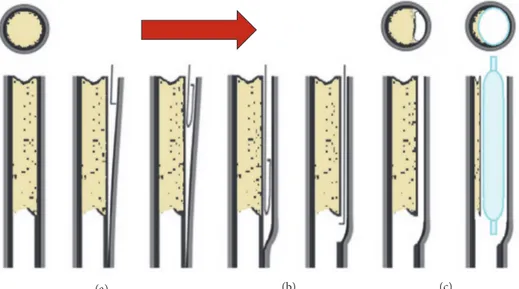
2.1. Balloon Folded Geometry. In the present work, the approach for creating a tri-wing folded configuration was similar to the one in [13] and FEM simulations were carried out in this regard. The sequence of steps for folding sim-ulation is reported in Figure 3. Starting from a cylindrical balloon of 3 mm diameter (as expected after inflation), during the first step (pressing) three cylindrical rigid surfaces (6 mm diameter), also known as punches, moved radially and pressed the balloon towards the internal cylindrical shaft. This first step ended with the punches stopping very close to the shaft (≈ 0.1 mm) to obtain a preliminary tri-winged shape of the balloon. In the second step (suction) of the simulation a negative pressure of -0.09 MPa was applied inside the balloon to force the balloon-shaft adhesion and to make the tri-winged profile sharper. During this step, once the inner pressure was low enough (< -0.07 MPa), to guarantee a realistic unfolded tri-winged shape, the punches were retracted of 2.5 mm to avoid any further interaction with the balloon. During the last step of the simulation, the final folding was obtained by rotating around the balloon axis a new set of punches with a sigmoid shape, while the inner negative pressure was maintained.
The whole simulation was carried out assuming quasi-static condition and a reference step time of 0.1s for each of the three steps.
The balloon was folded onto a supporting shaft, which was simply assumed as consisting of a much stiffer mate-rial compared to the other parts. The main dimensions (pre/postfolding) of the balloon (see Table 1) and material properties were taken as in [11], considering the balloon as linear elastic, with a Young modulus of 900 MPa and a Poisson coefficient of 0.4.
Finite element simulations were carried out using the commercial software DS Simulia Abaqus 2017©. The deformed configuration achieved through folding was then exported as an orphan mesh, to be later used as initial configuration for the subintimal angioplasty analysis. For the exported orphan mesh a “stress-free” condition was assumed; i.e., the presence of nonzero initial stresses in the balloon due to folding was considered negligible. The orphan mesh consisted of 110600 triangular elements to which membrane type properties were assigned (M3D3).
SHAFT BALLOON PUNCH PRESSING AND SUCTION FOLDING INITIAL BALLOON SHAPE INTERMEDIATE BALLOON SHAPE FINAL BALLOON SHAPE
Figure 3: Steps of the balloon folding simulation (note that the frontal view of the final balloon shape is enlarged).
2.2. CTO Model. For the present study, we considered the CTO as a solid cylinder (overall length 8 mm, diameter 3 mm), having both ends with concave caps (i.e., type II) as the most common scenario.
The structure of the CTO may evolve over time and exhibit heterogeneous and spatially varying composition. Ideally, a patient-specific CTO composition should be used, but this approach is not yet feasible, although progress has been reported towards in vivo characterization [23]. Since it is very difficult to assess in vivo the spatial distribution of various constituents [17], a possible approach to accounting for these variations, at least on a macro-scale, is to subdivide the CTO into regions with different sets of associated proper-ties. To start with, a heterogeneous CTO model was created, with distal and proximal fibrous caps enclosing a softer core region, corresponding to the initial thrombus. The core is surrounded by a fibrous layer at the interface with the artery, to account for local thickening and change of properties of diseased intima. These fibrous regions were considered as stiffer tissues and following the approach described in [24], a hyperelastic behavior was assumed, based on the definition of the following strain energy function:
𝑊 = 𝐶10(𝐼1− 3) + 𝐶01(𝐼2− 3) + 𝐶20(𝐼1− 3)2 + 𝐶11(𝐼1− 3) (𝐼2− 3) + 𝐶30(𝐼1− 3)3 (1)
Table 2: Coefficients of hyperelastic law used for the plaque.
C10 C01 C20 C11 C30
[MPa] [MPa] [MPa] [MPa] [MPa]
-0.49596 0.50661 3.6378 1.19353 4.73725
in which I1 and I2 are the first and second strain invari-ants and Cij are material coefficients. This model is based on data reported for partial occlusions in [20], in which plaques were classified histologically as either cellular, hypocellular, or calcified. Since a CTO essentially repre-sents the final stage of the evolution of an atherosclerotic plaque, it usually exhibits a higher degree of calcification. Therefore, we considered more reasonable using values of coefficients Cij reported in [24] for calcified plaques (see Table 2 ).
Direct measurements of core properties were not avail-able, but for shear modulus of thrombus values in the range 14-21 kPa were reported [25]. Since the coefficients Cji in the strain energy function reported in (1) are related to the initial shear modulus, by properly scaling their values a suitable equivalent shear stiffness can be obtained for the core while keeping the same constitutive law. In particular, the spatial variation of properties can be conveniently managed
FIBROUS (stiffer)
LIPIDIC (softer)
transition
Figure 4: CTO model.
by introducing a field variable T to control the scaling of the coefficients, as per
𝐶𝑖𝑗= 𝐶𝑖𝑗∗ 𝑇 (𝑅, 𝑍) (2) where R and Z are the radial and axial coordinates of a cylindrical reference system (with the origin on the axis of plaque). The transition from an outer (stiffer) fibrous shell to the inner cylindrical core domain (softer) was achieved through the functions as per
𝑇 = 2 +1
2(tanh (𝐾V𝑎𝑟(𝑅 − 𝑅𝑙𝑖𝑚)) − tanh (𝐾V𝑎𝑟(𝑅 + 𝑅𝑙𝑖𝑚))
+ tanh (𝐾V𝑎𝑟(𝑍 − 𝑍𝑙𝑖𝑚)) − tanh (𝐾V𝑎𝑟(𝑍 + 𝑍𝑙𝑖𝑚))) (3)
in which Rlimand Zlimare the outer limits of the soft core (i.e., thrombus) and Kvaris a coefficient that controls how abrupt is the variation from/to the fibrous material properties. The resulting heterogeneous CTO model is shown in Figure 4, in which at the interface between CTO and artery the presence of a fibrous layer 0.2 mm thick can be noticed.
Since the structure of the CTO evolves over time and depends on lesion age, we then considered two different scenarios, one in which a large soft core is still present (heterogeneous CTO) and one in which the plaque is more uniformly calcified (homogeneous CTO).
Moreover, as already mentioned, it is important to include some form of permanent damage in response to the extreme deformation induced by balloon inflation in order to account for permanent deformation of the occlusion after angioplasty. Otherwise, when the device is retracted, an unrealistic total recovery of plaque deformation would follow. To this aim, we coupled hyperelasticity with plasticity as also proposed in [22]. Unfortunately, for CTOs very little information about plastic yield stress or failure strength is available. As a first estimate, we assumed yield stress value to be 0.3 MPa, which according to [26] is the threshold stress value that induces plaque rupture (most used within FE studies). To include permanent damage of the core, plastic yield stress was set to 30 kPa, i.e., slightly lower than tensile strength between 50 and 150 kPa reported in [25]. Following [24], a hyperelastic behavior was assumed for the arterial wall. The layered structure of the artery was not considered; i.e., the tunica intima was not directly modeled, assuming a negligible mechanical contribution, and the balloon was inserted in a
false lumen at the interface between CTO and arterial wall. A surrounding layer was tied to the external surface of the artery to simulate embedding within internal tissues. Following [27] it consisted of a cylinder (3 mm thickness) modeled assuming hyperelastic behavior with a Neo-Hookean strain energy function (C10= 150 kPa) as per (4).
𝑊 = 𝐶10(𝐼1− 3) (4) 2.3. Subintimal Angioplasty Model. The components includ-ed in the subintimal angioplasty analysis were balloon, shaft, CTO, artery, and a surrounding layer that embeds the artery. As shown in Figure 5, the artery consisted of a straight hollow cylinder (internal diameter 3 mm, thickness 0.25 mm, length 20 mm).
The analysis was divided into the steps summarized in Figure 5.
The first phase consisted in the creation of an eccentric false lumen and the insertion of shaft and balloon. In the clinical procedure, the path for the catheter results from the insertion of the guidewire in the subintimal space. In our model (see steps 1, 2 in Figure 5), this is achieved by temporar-ily lifting a quarter of the edge of the occluded artery. Then, the shaft is advanced towards the vessel, temporarily applying a small pressure on top of the plaque, to create a small lumen that helps facilitating the insertion. Between plaque and artery, a contact interaction is defined with a maximum friction shear stress value, limited to an appropriate cap until the shaft with the balloon is fully inserted. After releasing the edge, the pressure on the plaque and the cap on the maximum friction shear stress were removed, letting the artery relax onto the shaft and the balloon. At this point (step 3), the balloon is inflated up to a reference pressure of 12 bar [10]. Finally, the balloon is deflated (step 4) and by deactivating the contact interaction between the group shaft-balloon and the other components, the CTO is left free to recover any elastic deformation and reach its final (permanent) deformed configuration (step 5).
Boundary conditions, specifically for the inflation and deflation process, were kept as simple as possible. The shaft was only constrained to have the proximal end parallel to the ends of the vessel. The artery was only blocked along its axis on both ends. Due to the combined presence of large deformation, material nonlinearities, and multiple complex contact interactions, an explicit solver (DS Simulia Abaqus 2017©) was adopted. We considered a global contact inter-action with a unique friction coefficient of 0.2. Mass scaling
SHAFT BALLOON ARTERY SURROUNDING TISSUE PLAQUE 1) LIFTING 2) INSERTION 3) INFLATION 4) DEFLATION 5) EXTRACTION
Figure 5: Components of subintimal angioplasty model and sequence of analysis steps (surrounding tissue not shown in procedure steps).
was implemented, and a small viscous pressure was applied to all the bodies to enhance stability. To ensure that the inertial forces were negligible throughout the simulation and do not cause unrealistic dynamic effects, the ratio of kinetic energy to the total strain energy was consistently maintained lower than 5% [10], while also checking that no significant changes to the physics of the model were determined by the viscous pressure.
3. Results
3.1. Balloon Subintimal Deployment, Inflation, and CTO Deformation. The progressive deployment of the balloon in the subintimal space and consequent deformation of the CTO is represented in Figure 6 (surrounding tissue is not shown) for heterogeneous configuration. As shown, the proposed approach allowed the simulation of the most relevant phases of subintimal angioplasty, including inflation of a folded balloon from an eccentric position and subsequent deflation and extraction. Contour maps refer to plastic equivalent strain (PEEQ), to highlight regions where yield stress is exceeded resulting in permanent damage. Because of the forced insertion of the balloon and the shaft in the subintimal false lumen, some regions of the CTO undergo plastic
deformation even before the inflation of the balloon. At the end of inflation phase, the heterogeneous CTO was nearly completely compressed, with a significant amount of plastic strain, up to more than 2.0 in the fibrous regions. After the balloon was deflated and removed, the CTO partially recov-ered the deformation reaching peak pressure. The permanent deformations induced in the fibrotic wall and in the softer core are not enough to hold completely the spring back of the whole plaque.
As already mentioned, simulations were also carried out considering CTO with no soft core (i.e., homogeneous CTO). Results for this latter case are reported in Figure 7. For this configuration at the end of inflation phase, the peaks of equivalent plastic strain (approx. 0.98) were localized near the concave ends and a significant portion of the central region of the CTO remained in the elastic field. At the end of the procedure, despite a further small increase of peak plastic deformation near proximal and distal fibrous caps, the CTO recovered its original shape to a significant amount, due to elastic recovery of the central region. In general, considering maximum plaque deformation at peak pressure, significant differences could be noticed when comparing homogeneous and heterogeneous occlusions. These may indicate that homogeneous CTOs, exhibiting large calcified
0.60 0.55 0.50 0.45 0.40 0.35 0.30 0.25 0.20 0.15 0.10 0.05 0.00 PEEQ (Avg: 75%) 3.50 3.21 2.92 2.63 2.33 2.04 1.75 1.46 1.17 0.88 0.59 0.29 0.00 0.88 0.59 0.29 0.00 PEEQ (Avg: 75%) PEEQ (Avg: 75%) 3.50 3.60 3.21 2.92 2.63 2.33 2.04 1.75 1.46 1.17 AFTER INSERTION AFTER INFLATION AFTER EXTRACTION
Figure 6: Progressive deformation of CTO with heterogeneous composition.
content, could be tough enough to resist compressive action exerted by the balloon. These results also indicate that the model is able to reflect changes of CTO properties that may occur on a patient-specific basis (provided, of course, they are available).
Although including the guidewire for false lumen cre-ation and reenter would mimic real opercre-ations more closely, the goal of reproducing balloon inflation from an eccentric position and starting from a fully occluded lumen was successfully achieved.
3.2. Arterial Lumen Restoration. From a clinical point of view, the most relevant result of the simulation is the degree of lumen restoration at the end of the whole procedure. In order to provide a quantitative evaluation of this index, we calculated the percentage ratio between unoccluded (i.e., restored) and total arterial lumen during the different phases of the procedure, as reported in Figure 8.
The curves refer to middle and proximal transversal sections of the CTO and occluded artery. By means of a Matlab© script previously developed by the authors [28], the effective areas of CTO and artery could be computed from corresponding images extracted from output database for each step of the calculation. For heterogeneous CTO,
due to the presence of fibrous caps and balloon transition ends, the amount of lumen restoration varied slightly along the longitudinal axis, but at peak inflation pressure it was up to nearly 80%. The residual restored lumen was between 35% and 45%, depending on the section considered. For homogeneous CTO the lumen restoration at peak inflation pressure was lower and varied more significantly for middle and proximal section (i.e., from 65% to 75%, respectively). Quite obviously, differences on the maximum achievable plaque deformation reflected the different stiffness and spatial arrangement of constituents. CTO configuration has an even more remarkable effect considering postprocedural plaque residual deformation. As anticipated, for homogeneous CTO it was reduced down to 10-25%, indicating a lower efficacy of the treatment and possibly the need for higher inflation pressure.
These results can be compared with clinical evidence reported in literature (mostly for partial occlusion) concern-ing plaque reduction and recoil after balloon angioplasty with or without stenting. As an example, in [29] a video-densitometric technique was used to analyze stenosis mor-phology directly after angioplasty. For a mean balloon cross-sectional area of 5.3± 1.6 mm2and vessel reference area of 6.0 ± 2.6 mm2, after balloon angioplasty only, minimal luminal
0.20 0.21 0.18 0.17 0.15 0.13 0.12 0.10 0.08 0.07 0.05 0.03 0.02 0.00 PEEQ (Avg: 75%) 0.90 0.92 0.82 0.75 0.67 0.60 0.52 0.45 0.37 0.30 0.22 0.15 0.07 0.00 PEEQ (Avg: 75%) PEEQ (Avg: 75%) AFTER INSERTION AFTER INFLATION AFTER EXTRACTION 0.90 1.35 0.82 0.75 0.67 0.60 0.52 0.45 0.37 0.30 0.22 0.15 0.07 0.00
Figure 7: Progressive deformation of CTO with homogeneous composition.
0% 10% 20% 30% 40% 50% 60% 70% 80% 90% 100% 0 0.2 0.4 0.6 0.8 1 1.2 1.4 1.6 L umen t o a rt er y s ec tio n ra tio Time [s] Hetero Proximal Hetero Middle Homo Proximal Homo Mid 1) 2) 3) 4) 5) LIFTIN G INS ER TI O N INFL ATI O N DE FL AT ION EX TR A CTI O N
+1.10e+00 +1.01e+00 +9.17e-01 +8.25e-01 +7.33e-01 +6.42e-01 +5.50e-01 +4.58e-01 +3.67e-01 +2.75e-01 +1.83e-01 +9.17e-02 +0.00e+00 S, Mises (Avg: 75%)
(a) HETEROGENOUS PLAQUE (b) HOMOGENOUS PLAQUE
Figure 9: Stress state on the arterial wall at maximum inflation pressure.
cross-sectional area was 2.8± 1.4 mm2 (i.e., corresponding to about 50% lumen restoration). In [30] for vessels with comparable dimensions with the one of the present study but with partial occlusion, stenosis was reduced to 31% after balloon inflation. Although these data were presented with different metrics, they compare very favorably with model prediction of postprocedural unoccluded lumen in the range 40-50%.
It also interesting to consider differences between peak and residual compression of the CTO, which correspond to the loss of potential lumen again as a consequence of recoil after balloon deflation. This aspect has been investigated in [31]. By means of quantitative coronary angiography, the recoil ratios of percutaneous transluminal coronary angioplasty were 30.43±14.89%. Similar values (22.9%) were reported in [32] with a computational model, in which hyperelastic behavior was assumed for the artery and the plaque was instead modeled as a viscoplastic material to prevent complete elastic recoil. These values are very close to model predictions for heterogeneous plaque, in which case the reduction of lumen gain after deflation is about 30%. For the homogeneous occlusions, the recovery is instead more pronounced (about 50%). It should be noted that the reduction of the restored lumen from peak inflation to complete deflation of the balloon depends on the recovery of transient artery stretch and elastic recoil of the occlusion. Since in the present model no damage is considered for the artery, the amount of recoil could be slightly overestimated, which might explain, at least partially, the behavior observed for the homogeneous plaque.
3.3. Arterial Stress State. During angioplasty, the arterial wall is potentially subjected to nonphysiological overstretching. The analysis of arterial stress state can provide useful insights to identify critical operating condition with risk of arterial
rupture. For the present procedure, the most critical condi-tion is reached at peak inflacondi-tion pressure. The corresponding von Mises stresses are shown in Figure 9.
The peak stress is 1.1 MPa and it is localized in transition regions where the artery is deformed by the stiffer proximal and distal caps of the CTO, on the intimal side of the arterial wall. The remaining central region is more uniformly loaded with a stress level in the order of 0.6 MPa.
In order to evaluate how critical is the stress state, it should be compared with arterial strength. This can hardly be estimated in vivo, but some reference values from ex vivo tests on human arteries can be found in [26]. Uniaxial ultimate strength for iliac arteries in circumferential directions was 1.03±0.31 MPa for tunica adventitia, 1.07±0.29 for diseased tunica media, and 0.77±0.29 for diseased intima. With the described model setup, the peak von Mises stress was really close to these limits, confirming that subintimal procedure involves a stress condition potentially leading to artery damage.
Considering the homogeneous CTO, the peak stress level is 1.13 MPa, and because of reduced compression of the central region of the CTO, the corresponding portion of the artery is more uniformly stretched. The peak stress is not localized but a rather large volume of the arterial wall is subjected to a high stress level, possibly indicating a more critical condition.
For the homogeneous CTO the region subjected to a high stress level is more extended and, correspondingly, there could be a higher potential risk of rupture in a weak point, due to local variations of the strength of the arterial wall. Moreover, as previously observed, the postprocedural lumen restoration was limited. Higher balloon pressures would be needed during dilation procedures, which may imply even higher risks of vessel injury and procedural complications (i.e., barotraumas) all resulting in greater localized damage and higher restenosis rates.
Figure 10: Balloon orphan mesh.
4. Discussion
The main goals of the work were to investigate the fea-sibility of FEM simulation of CTO subintimal angioplasty considering the possibility of including the initially folded configuration of the balloon, simulating the most relevant phases and predicting postprocedural outcomes.
With regard to the folding simulations, from a modeling point of view, a first relevant finding is that the proposed approach, based on orphan mesh (see. Figure 10), proved to be quite effective in obtaining a realistic shape. In particular, it can be observed how the presence of the transition regions influences the final geometry of the folded balloon, leading us to a final folded shape that could be compared to the real folded balloons.
It has to be remarked that if the FEM code for balloon angioplasty simulation is the same (i.e., Abaqus), this is the most straightforward option, since the part can be readily imported. A practical disadvantage of using an orphan mesh is that the application of load or boundary conditions to selected regions on an element basis can be seriously tedious for a model with thousands of elements and complex shape. This problem can be bypassed by defining proper surfaces and sets already in the folding models, provided the same code is used. In principle, the use of an orphan mesh would also allow exporting the stress state in the balloon at the end of the folding process and using it as initial condition successive models. In the authors’ opinion, this is not necessarily the most convenient and realistic option, both due to assumptions adopted for the balloon in the folding simulations (i.e., no form of permanent deformation was considered) and because the balloon undergoes thermal treatments for stress relaxation after the folding process.
Another original contribution of the present work is the definition of a procedure for the insertion and inflation of a folded balloon into the limited and highly confined space of the false lumen, since no previous models are available in literature. In particular, it should be remarked that in comparison with partial occlusions models, for which the insertion is less problematic and there is more room for balloon inflation, for CTO the model is more challenging. A peculiar aspect addressed in the present work is the management of multiple complex contact interactions. These included self-contact for the folded balloon wings, contact between inner balloon surface and shaft, and contact between balloon outer surface, CTO, and artery.
Considering predictions of postprocedural outcomes, results showed that the model can be used to investigate both structural and functional aspects and results were shown to depend significantly on CTO configuration. In this respect, with the described approach based on field dependent properties, it is also straightforward to generate different distributions, since it is not necessary to partition CTO geometry into distinct regions with different properties. Of course, a key role is played by material properties and constitutive modeling assumptions. In the present model, we found that a constitutive modeling approach on hyperelastic strain energy functions coupled with plasticity can effectively account for large deformations and permanent damage after the procedure. It should be noted that the use of isotropic hyperelastic laws is a common approach in the context of angioplasty simulations to account for the large and not physiological overstretch to which plaque constituents may be subjected. However, as discussed in [33], published models concerning angioplasty or stenting procedures, often adopted different strain energy functions to apparently fit the same data. This may introduce an additional source of variability, especially in presence of a complex stress state such as the one experienced in CTO compression. The choice of yield stress value is also a key point, because it may dictate the extension of the plasticized region and the related amount of recoil. Since precise information about yield stress levels or damage thresholds for CTO are not yet available, in a previous investigation [33] we carried out a sensitivity study on the influence of yield stress on a simplified model for CTO compression. By decreasing yield stress from 0.3 MPa to 0.05 MPa, the residual deformation of a homogeneous CTO increased from 22% to 39%. In particular, a reduction of the yield stress below 0.1 MPa did not lead to a significant increment in the residual deformation, whereas setting yield limit higher than 0.3 MPa resulted in very limited plastic deformation, which may result in an unrealistically high pressure to compress the CTO.
Considering plaque compression and permanent lumen restoration, our model provided results comparable with clinical findings and the differences between heterogeneous and homogeneous CTO demonstrated that it is sensitive to variations on plaque composition. As already mentioned, composition, degree of calcification, and spatial distribution of the constituents of a CTO are highly variable and depend-ing on type, age, and vascular district considered. Therefore, in order to use this approach on a patient-specific basis, there
is a need for a deeper knowledge of mechanical properties and damage mechanisms of CTOs. In particular, a key aspect is how to obtain in vivo patient-specific properties of diseased vascular regions. Interestingly, methods like static or dynamic Magnetic Resonance Elastography [34] or researches on the correlation between MRI characteristics of CTOs and the amount of force required for a guidewire to puncture [23] may help, in the future, to determine the stiffness of CTOs directly in vivo leading to suitable material data to feed to our model.
Considering the risks of arterial rupture associated with subintimal angioplasty, the stress values predicted were very close to (if not exceeding) average values reported in literature for adventitial and fibrous media in ex vivo tests on samples from atherosclerotic regions. These results confirmed that the arterial wall is exposed to nonphysiological overstress and that during balloon angioplasty a sort of “controlled” damage is applied to the wall of stenotic artery when compressing the occlusion to restore blood flow. Clearly, caution should be exerted when comparing with numerical predictions, also considering that the presence of residual stresses was not included in the model.
5. Limitations
Although with the proposed approach the key steps of the subintimal angioplasty procedure were virtually replicated, the setup of a realistic model of this procedure remains challenging and some limitations apply. In particular, while a development of methods for in vivo measurement of composition and mechanical properties of both CTO and diseased arteries could be expected in the future, at present several assumptions are still necessary.
In the present work idealized geometries of artery and CTO were considered, and constitutive models adopted were based on the assumption of isotropic elastic response. Although these hypotheses are indeed common in published literature concerning simulation of complex percutaneous procedure such as stent/balloon angioplasty [35, 36], they may obviously affect numerical outcomes. When reliable methods to assess patient-specific CTO configurations and blood vessel structure will be available, including anisotropic behavior or presence of a layered structure for arterial wall will help increasing accuracy.
A further possible limitation is that although a method is provided to account for the presence of regions with different stiffness, such as the necrotic core, by means of the field function, the presence of fibrotic capsules, as well as of other localized variations, was not investigated. These were not included mainly because literature data adopted for the CTO referred to the plaque as a whole. On the other hand, accounting for such local heterogeneities may improve the accuracy of numerical outcome, but only provided that clinical data are available also on spatial distribution and size, as well as mechanical properties of the different constituents. Finally, considering collateral effects of subintimal angio-plasty, it should also be noted that induced damage could take several forms, including irreversible deformation of arterial
tissue caused by overstretch or local dissections. Damage of arterial wall is thought to contribute over the long term to restenosis, leading to eventual reocclusion of the treated vessel. Examples of computational simulations of arterial damage due to overstretch and inelastic deformation or plaque fracture have been reported in the literature [37, 38]. Their inclusion in the model could be a possible improvement of the present one.
The dissection of the plaque or of intimal layer from the underlying vessel and its possible extension to collateral vessels is also a major risk. Some insights for a possible approach can be found in the work of [27], in which cohesive elements were introduced in a 2D model of a highly stenotic artery. However, its extension to 3D model is not trivial, in particular for the present model of CTO. The inclusion of a thin intimal layer in the current model, in which explicit solver is used, could prove to be very difficult and would make sense only if adequate knowledge of cohesive properties is available for atherosclerotic plaques.
6. Conclusion
In the present work, we proposed an original FEM modeling approach for CTO subintimal angioplasty, demonstrating the feasibility of successfully simulating the inflation of a folded balloon in the restricted space of a false lumen at the interface between CTO and artery. To the author’s knowledge there is no previous literature about this type of simulation of percutaneous treatment, in particular, when also taking into account initially folded configuration of the balloon.
From a modeling point of view, the proposed approach is based on a preliminary simulation of the folding process used to feed the folded balloon geometry as an orphan mesh to a successive simulation of the key steps of the subintimal CTO treatment (i.e., insertion, inflation, and extraction of the balloon).
This approach proved to be effective and its predictive capabilities were evaluated by comparing CTO configura-tions with concave cap morphology and both heterogeneous and homogeneous compositions.
The degree of lumen restoration and plaque recoil after balloon extraction varied significantly depending on assump-tions for CTO configuration. Values of peak von Mises stress in the arterial wall were close to reported ex-vivo strength of arteries in presence of atherosclerosis, but with more uniform distribution for homogeneous highly calcified plaque. Since this configuration also determined lower residual lumen restoration, higher inflation pressure could be required, with associated increase of peak stress and risk of arterial rupture. Overall, results compared favorably with data reported in literature for postprocedural lumen restoration and arterial stress data, confirming potential usefulness of the approach, especially if the future model could include patient-specific CTO properties.
In conclusion, results indicate that a realistic model could indeed provide important information both from a clinical point of view (with regard to artery damage or dissection following the treatment) and from a product engineering
point of view (i.e., problems related to device stabilization or effects of different folding methods).
Data Availability
No data were used to support this study.
Conflicts of Interest
The authors declare that they have no conflicts of interest.
References
[1] H. Al-Ameri, L. Clavijo, R. V. Matthews, R. A. Kloner, and D. M. Shavelle, “Devices to treat peripheral chronic total occlusions,”
Journal of Interventional Cardiology, vol. 25, no. 4, pp. 395–403,
2012.
[2] A. Bolia, R. D. Sayers, M. M. Thompson, and P. R. F. Bell, “Subintimal and intraluminal recanalisation of occluded crural arteries by percutaneous balloon angioplasty,” European Journal
of Vascular and Endovascular Surgery, vol. 8, no. 2, pp. 214–219,
1994.
[3] U. Schwarzw¨alder and T. Zeller, “Debulking Procedures: Poten-tial Device Specific Indications,” Techniques in Vascular and
Interventional Radiology, vol. 13, no. 1, pp. 43–53, 2010.
[4] S. David Chua, B. Mac Donald, and M. Hashmi, “Finite element simulation of stent and balloon interaction,” Journal of Materials
Processing Technology, vol. 143-144, pp. 591–597, 2003.
[5] F. Gervaso, C. Capelli, L. Petrini, S. Lattanzio, L. Di Virgilio, and F. Migliavacca, “On the effects of different strategies in modelling balloon-expandable stenting by means of finite element method,” Journal of Biomechanics, vol. 41, no. 6, pp. 1206–1212, 2008.
[6] D. E. Kiousis, A. R. Wulff, and G. A. Holzapfel, “Experimental studies and numerical analysis of the inflation and interaction of vascular balloon catheter-stent systems,” Annals of Biomedical
Engineering, vol. 37, no. 2, pp. 315–330, 2009.
[7] T. C. Gasser and G. A. Holzapfel, “Modeling plaque fissuring and dissection during balloon angioplasty intervention,” Annals
of Biomedical Engineering, vol. 35, no. 5, pp. 711–723, 2007.
[8] A. Karimi, M. Navidbakhsh, H. Yamada, and R. Razaghi, “A nonlinear finite element simulation of balloon expandable stent for assessment of plaque vulnerability inside a stenotic artery,”
Medical & Biological Engineering & Computing, vol. 52, no. 7, pp.
589–599, 2014.
[9] D. Martin and F. Boyle, “Finite element analysis of balloon-expandable coronary stent deployment: Influence of angio-plasty balloon configuration,” International Journal for
Numer-ical Methods in BiomedNumer-ical Engineering, vol. 29, no. 11, pp. 1161–
1175, 2013.
[10] H. Zahedmanesh, D. John Kelly, and C. Lally, “Simulation of a balloon expandable stentin a realistic coronary artery-determination of the optimum modellingstrategy,” Journal of
Biomechanics, vol. 43, no. 11, pp. 2126–2132, 2010.
[11] M. De Beule, P. Mortier, S. G. Carlier, B. Verhegghe, R. Van Impe, and P. Verdonck, “Realistic finite element-based stent design: The impact of balloon folding,” Journal of Biomechanics, vol. 41, no. 2, pp. 383–389, 2008.
[12] J. Bukala, P. Kwiatkowski, and J. Malachowski, “Numerical anal-ysis of crimping and inflation process of balloon-expandable
coronary stent using implicit solution,” International Journal for
Numerical Methods in Biomedical Engineering, vol. 33, no. 12,
e2890, 11 pages, 2017.
[13] S. Delorme, D. Laroche, R. DiRaddo, and J. Buithieu, “Modeling polymer balloons for angioplasty: From fabrication to deploy-ment,” in Proceedings of the ANTEC 2004 - Annual Technical
Conference Proceedings, pp. 3375–3379, USA, May 2004.
[14] S. Sumitsuji, K. Inoue, M. Ochiai, E. Tsuchikane, and F. Ikeno, “Fundamental wire technique and current standard strategy of percutaneous intervention for chronic total occlusion with histopathological insights,” JACC: Cardiovascular Interventions, vol. 4, no. 9, pp. 941–951, 2011.
[15] S. Yalonetsky, A. B. Osherov, and B. H. Strauss, “The Pathobi-ology of CTO,” in Chronic Total Occlusions, pp. 1–8, John Wiley and Sons, Oxford, England, 2013.
[16] F. Saab, M. R. Jaff, L. J. Diaz-Sandoval et al., “Chronic Total Occlusion Crossing Approach Based on Plaque Cap Mor-phology: The CTOP Classification,” Journal of Endovascular
Therapy, vol. 25, no. 3, pp. 284–291, 2018.
[17] T. Roy, G. Liu, X. Qi, A. Dueck, and G. A. Wright, “MRI characterization of peripheral arterial chronic total occlusions at 7 Tesla with microCT and histologic validation,” Journal of
Cardiovascular Magnetic Resonance, vol. 17, no. Suppl 1, p. P404,
2015.
[18] L. Riel, S. Dion, M. Brouillette, S. B´erub´e, M. Despatis, and ´E. Bousser, “Characterization of Calcified Plaques Retrieved From Occluded Arteries and Comparison With Potential Artificial Analogues,” in Proceedings of the ASME 2014 International
Mechanical Engineering Congress and Exposition, Montreal,
Quebec, Canada, 2014.
[19] M. T. Walsh, E. M. Cunnane, J. J. Mulvihill, A. C. Akyildiz, F. J. H. Gijsen, and G. A. Holzapfel, “Uniaxial tensile testing approaches for characterisation of atherosclerotic plaques,”
Journal of Biomechanics, vol. 47, no. 4, pp. 793–804, 2014.
[20] H. M. Loree, A. J. Grodzinsky, S. Y. Park, L. J. Gibson, and R. T. Lee, “Static circumferential tangential modulus of human atherosclerotic tissue,” Journal of Biomechanics, vol. 27, no. 2, pp. 195–204, 1994.
[21] E. M. Cunnane, J. J. E. Mulvihill, H. E. Barrett et al., “Mechan-ical, biological and structural characterization of human atherosclerotic femoral plaque tissue,” Acta Biomaterialia, vol. 11, no. 1, pp. 295–303, 2015.
[22] D. Gastaldi, S. Morlacchi, R. Nichetti et al., “Modelling of the provisional side-branch stenting approach for the treatment of atherosclerotic coronary bifurcations: Effects of stent position-ing,” Biomechanics and Modeling in Mechanobiology, vol. 9, no. 5, pp. 551–561, 2010.
[23] T. Roy, G. Liu, N. Shaikh, A. D. Dueck, and G. A. Wright, “Puncturing Plaques,” Journal of Endovascular Therapy, vol. 24, pp. 35–46, 2017.
[24] I. Pericevic, C. Lally, D. Toner, and D. J. Kelly, “The influence of plaque composition on underlying arterial wall stress during stent expansion: the case for lesion-specific stents,” Medical
Engineering & Physics, vol. 31, no. 4, pp. 428–433, 2009.
[25] I. Karˇsaj and J. D. Humphrey, “A mathematical model of evolving mechanical properties of intraluminal thrombus,”
Biorheology, vol. 46, no. 6, pp. 509–527, 2009.
[26] G. A. Holzapfel, G. Sommer, and P. Regitnig, “Anisotropic mechanical properties of tissue components in human atherosclerotic plaques,” Journal of Biomechanical Engineering, vol. 126, no. 5, pp. 657–665, 2004.
[27] P. Badel, S. Avril, M. A. Sutton, and S. M. Lessner, “Numerical simulation of arterial dissection during balloon angioplasty of atherosclerotic coronary arteries,” Journal of Biomechanics, vol. 47, no. 4, pp. 878–889, 2014.
[28] A. Avanzini and D. Battini, “Structural analysis of a stented peri-cardial heart valve with leaflets mounted externally,” Proceedings
of the Institution of Mechanical Engineers, Part H: Journal of Engineering in Medicine, vol. 228, no. 10, pp. 985–995, 2014.
[29] B. J. Rensing, W. R. Hermans, B. H. Strauss, and P. W. Ser-ruys, “Regional differences in elastic recoil after percutaneous transluminal coronary angioplasty: A quantitative angiographic study,” Journal of the American College of Cardiology, vol. 17, no. 6, pp. 34–38, 1991.
[30] J. Baptista, C. d. Mario, Y. Ozaki et al., “Impact of plaque morphology and composition on the mechanisms of lumen enlargement using intracoronary ultrasound and quantitative angiography after balloon angioplasty,” American Journal of
Cardiology, vol. 77, no. 2, pp. 115–121, 1996.
[31] S. L. Chen, N. S. Guo, and H. D. Chen, “The immediate elastic recoil of percutaneous coronary angiography and intracoronary stent implantation,” Radiology Research and Practice, vol. 10, pp. 726–728, 2001.
[32] D. K. Liang, D. Z. Yang, M. Qi, and W. Q. Wang, “Finite element analysis of the implantation of a balloon expandable stent in a stenosed artery,” International Journal of Cardiology, vol. 104, pp. 314–318, 2005.
[33] A. Avanzini, C. Vecchi, D. Battini, and C. T. Occlusion, “Influ-ence of plaque properties and constitutive modeling approach on the simulation of percutaneous angioplasty of chronic total occlusions,” in AIMETA 2017 XXIII Conference The Italian
Association of Theoretical and Applied Mechanics, L. Ascione, B.
Valentino, F. Luciano et al., Eds., 2017.
[34] B. Kates, K. J. Anderson, and G. A. Wright, “Magnetic Reso-nance Elastography for Measuring the Compliance of Occlusive Vascular Disease,” in Proceedings of the International Society for
Magnetic Resonance in Medicine, vol. 21, 2013.
[35] A. Karimi, M. Navidbakhsh, R. Razaghi, and M. Haghpanahi, “A computational fluid-structure interaction model for plaque vulnerability assessment in atherosclerotic human coronary arteries,” Journal of Applied Physics, vol. 115, no. 14, 2014. [36] A. Karimi, R. Razaghi, A. Shojaei, and M. Navidbakhsh,
“An experimental-nonlinear finite element study of a balloon expandable stent inside a realistic stenotic human coronary artery to investigate plaque and arterial wall injury,”
Biomedi-zinische Technik. Biomedical Engineering, vol. 60, no. 6, pp. 593–
602, 2015.
[37] D. Balzani, S. Brinkhues, and G. A. Holzapfel, “Constitutive framework for the modeling of damage in collagenous soft tissues with application to arterial walls,” Computer Methods
Applied Mechanics and Engineering, vol. 213/216, pp. 139–151,
2012.
[38] A. Ferrara and A. Pandolfi, “Numerical modelling of fracture in human arteries,” Computer Methods in Biomechanics and
Hindawi www.hindawi.com Volume 2018
Mathematics
Journal of Hindawi www.hindawi.com Volume 2018 Mathematical Problems in Engineering Applied Mathematics Hindawi www.hindawi.com Volume 2018Probability and Statistics
Hindawi
www.hindawi.com Volume 2018
Hindawi
www.hindawi.com Volume 2018
Mathematical PhysicsAdvances in
Complex Analysis
Journal ofHindawi www.hindawi.com Volume 2018
Optimization
Journal of Hindawi www.hindawi.com Volume 2018 Hindawi www.hindawi.com Volume 2018 Engineering Mathematics International Journal of Hindawi www.hindawi.com Volume 2018 Operations Research Journal of Hindawi www.hindawi.com Volume 2018Function Spaces
Abstract and Applied AnalysisHindawi www.hindawi.com Volume 2018 International Journal of Mathematics and Mathematical Sciences Hindawi www.hindawi.com Volume 2018
Hindawi Publishing Corporation
http://www.hindawi.com Volume 2013 Hindawi www.hindawi.com
World Journal
Volume 2018 Hindawiwww.hindawi.com Volume 2018Volume 2018
![Table 1: Geometric dimensions of the balloon. Pre-folding maximum diameter [mm] Post-folding maximumdiameter[mm] Diameter of the internal cylinder[mm] Thickness[mm] Overall Length[mm] 3.0 1.5 1 0.02 15](https://thumb-eu.123doks.com/thumbv2/123dokorg/5543877.65491/3.900.88.519.131.455/geometric-dimensions-diameter-maximumdiameter-diameter-internal-thickness-overall.webp)


