Building A Platform For UAV Research
by
Paolo Messina
Submitted to the Department of Electrical Systems and Automation (DSEA) on December 18, 2003, in partial fulfillment of the
requirements for the degree of “Laurea in Ingegneria Informatica”
Abstract
This work is part of an on-going research project in the field of Unmanned Aerial Vehicles and multiple vehicles coordination.
It mainly focuses on the production of a software architecture for UAV research, initially used for data acquisition and state estimation, and providing an easy to use and reliable test-bed for experiments and other research projects.
As an example of use, a horizon detection algorithm has been partially implemented to help state estimation with partial attitude recognition.
Thesis Supervisor: Mario Innocenti
Title: Full Professor and Vice-Chairman, Department of Electrical Systems and Au-tomation (DSEA), University of Pisa
Thesis Supervisor: Andrea Caiti
Title: Associate Professor, Department of Electrical Systems and Automation (DSEA), University of Pisa
Thesis Supervisor: Emilio Frazzoli
Title: Assistant Professor, Aeronautical and Astronautical Engineering Department, Coordinated Science Laboratory University of Illinois at Urbana-Champaign
Contents
1 Introduction 6
2 Project Overview 8
2.1 Unmanned Aerial Vehicles Testbed . . . 8
2.1.1 Hardware And Components . . . 8
2.2 Previous Work . . . 11
2.2.1 The Datalog Application . . . 12
2.3 Goals, Requirements and Design Principles . . . 13
2.4 Proposed Solution. . . 15
3 On Board System Setup And Configuration 16 3.1 Disk-On-Chip, Boot Image . . . 16
3.2 Startup Configuration . . . 18
4 On Board Software Solution 20 4.1 Operating System . . . 20
4.2 Software Architecture . . . 24
4.2.1 Threads, Multi-Threading Issues . . . 25
4.2.2 Watchdog and Managed Threads . . . 28
4.2.3 Utilities . . . 29
4.3 The Datalog++ Application . . . 30
4.3.1 Main Thread and Network Connectivity . . . 30
4.3.2 Sensing and Actuation . . . 32
4.3.3 Computational Threads . . . 34
5 On The Ground Solution 36 5.1 Goals And Requirements . . . 36
5.2 Design And Implementation . . . 37
5.2.1 Network Communication . . . 37
5.2.2 Software Architecture. . . 40
5.2.3 User Interface . . . 40
5.3 Using The Ground Station . . . 42
6 Experimenting With The UAV 44 6.1 Testing The Platform . . . 44
6.1.1 First Flight . . . 44
6.1.2 Second Flight . . . 45
6.2.1 Video Processing . . . 50
6.2.2 Horizon Detection Algorithm . . . 52
6.2.3 Testing and Results . . . 54
7 Conclusion 58 A MatrixLib 60 A.1 Goals and Requirements . . . 60
A.2 Implementation . . . 61
A.3 Comparison with Matlab . . . 68
A.4 Further Development . . . 70
B Log File Format 71 B.1 Binary Logs . . . 71 B.1.1 Record Format . . . 72 B.1.2 Begin Data . . . 72 B.1.3 End Data . . . 72 B.1.4 Format Comment . . . 73 B.1.5 Format Definition . . . 73 B.1.6 Data Block . . . 73 B.1.7 Byte Array . . . 74 B.2 Text Logs . . . 74
List of Figures
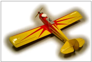
2-1 The airplane with the on-board computer. . . 9
4-1 On-Board User Application Architecture . . . 25
4-2 Main Thread . . . 31 4-3 Network Thread. . . 32 4-4 IMU Thread . . . 33 4-5 GPS Thread . . . 33 4-6 Servo Thread . . . 34 4-7 Estimator Thread . . . 34 4-8 Control Thread . . . 35 5-1 OSI Layers [1] . . . 37
5-2 Main Window - Watchdog Configuration . . . 41
5-3 IMU, GPS, Estimator Data . . . 41
5-4 Servo Board Data . . . 42
6-1 GPS Validity . . . 46
6-2 GPS Position . . . 47
6-3 GPS Analysis . . . 47
6-4 IMU Analysis . . . 48
6-5 Batteries Power from Servo Log . . . 49
6-6 Estimated Position (off-line) . . . 49
6-7 Horizon Detection Application . . . 50
6-8 DirectShow Filter Graph . . . 51
6-9 Radial distortion in video frames . . . 54
6-10 Transmission noise in video frames . . . 54
6-11 White stripe noise in video frames . . . 55
6-12 Color alterations in video frames . . . 55
List of Tables
4.1 Core Features: QNX Neutrino v6.2.1 [2] . . . 22
Chapter 1
Introduction
Research and development in the field of autonomous vehicles has always been at-tractive, for a variety of actual and potential applications in several different fields. Unmanned aerial, underwater and ground vehicles have been used in Earth and Space exploration, military reconnaissance and intelligence gathering, provision of data and services for commercial and scientific applications. Future applications could include law-enforcement, search and rescue, and even entertainment.
Unmanned vehicles can perform critical tasks without endangering the life of human pilots. They can be designed and developed without having to account for the presence of a pilot and the associated life-support and safety systems, potentially resulting in cost and size savings and increased operational capabilities [4].
Autonomous vehicle can reach places where human beings can’t survive or would risk their lives, like a disaster site or a contaminated area. And while single vehicles can perform tasks in hostile environments, multiple vehicles can cooperate to increase efficiency and reduce the risk — if a single vehicle fails the mission is over, if one of many fails the others can still accomplish the mission.
This work is part of an on going research project in the field of autonomous vehicles and multiple vehicles coordination at the Coordinated Science Laboratory, University of Illinois at Urbana-Champaign. The project is the joint effort of two research teams, working with ground and aerial vehicles.
Previous research by members of our team focused on the design and develop-ment of a distributed simulation environdevelop-ment for testing multiple vehicles coopera-tion scenarios and the implementacoopera-tion of an energy efficient coordinacoopera-tion algorithm for multiple unmanned aerial vehicles, to show the capabilities of the simulation en-vironment [5].
My work inside the project has been building a hardware and software platform upon our team airplane, to enable further research not only in a simulated envi-ronment, but also on the actual vehicle: from perfecting the hardware and operating system configuration on the on-board computer, to developing a software architecture for on-board applications, to setting up and developing a ground station for remote wireless communication with the airplane.
We also began to implement vision-based control by mounting a mini-camera on the airplane and developing a horizon detection algorithm for partial attitude recognition. Since our on-line estimator and controller were still at an early stage and the algorithm proved to be not very robust in the initial setup, this part is yet to be finished but is left as an example of the kind of research we can do with our platform.
Chapter 2
Project Overview
2.1
Unmanned Aerial Vehicles Testbed
Our project proposal was to build several — at least three — fixed-wing aircraft, capable of autonomous flight, designed to be able to perform well in a wide range of mission scenarios, preserving operational flexibility through adequate payload and maneuverability margins. For example, these airplanes are capable of performing aerobatic and other agile maneuvers, or can be used to demonstrate formation flying concepts and explore coordination problems with other aircraft or ground/surface vehicles.
2.1.1
Hardware And Components
The airframe of the UAVs are based on a commercially available “Almost Ready to Fly” (ARF) kit, namely the Spacewalker by “Great Planes, Inc.” The choice of an ARF model is due to the reduced effort required to assemble and test the model airplane prior to flight, with respect to a custom-built airplane, and to more traditional model kits.
However, the installation of the avionics box, sensors and instrumentation on board the airplane, as well as some handling, safety and reliability concerns, required some modifications of the original design, which have been already carried out
in-Figure 2-1: The airplane with the on-board computer
house and duly documented. These modifications consist essentially of an extension of the fuselage, re-distribution of weights, and a re-design of the control surface ac-tuation mechanisms. The standard-issue model aircraft servos offered limited control authority, which is not enough for many high-performance applications, e.g. aero-batic or “aggressive” flight. Enhanced control authority also translates to smaller phase lag and ultimately better safety. Hence we replaced the standard servos with high-torque, ball-bearing servos. Modifications to the airframe also include:
• stronger hinges at all control surfaces
• shorter, stiffer pushrods and bellcranks
• a 10-inch extension to the nose to push the firewall forward
• battery and fuel storage bays in the nose
• a reinforced, insulated center box section to hold the on-board computer
• avionics bays in the rear fuselage
• antenna mast and support wires
• dual elevator servos mounted in the empennage with external horns
• stronger tailwheel
• high-torque rudder servo
The Spacewalker was selected among similar models because of its size and pay-load capacity, stable flight characteristics, which do not prevent remarkable aerobatic capabilities, and its safety and durability. The flight characteristics (both in terms of handling and aerobatic capabilities) have been proved excellent in a series of human-piloted test flights with a fully-instrumented airplane, and with artificial payload increases (dead weight) up to a total of 13 pounds, which leaves ample margin for further development of the avionics or other payloads (e.g. vision systems).
The inherent stability of the airplane, redundant and independent servos, and a steel undercarriage and tail wheel assembly, provide a good level of reliability and sturdiness to the airplane, which are especially attractive for the intended exper-imental activity. (In fact, the SpaceWalker is certified both by the International Miniature Aircraft Association, IMAA and by the International Miniature Aerobatic Club, IMAC.)
The plane is powered by an “O.S. Engines” four-stroke Surpass II 0.91 cubic inch displacement nitro-fueled hobby engine with fuel pump, producing about 2.2 horsepower (2 kW) through a 14” propeller. The fuel tank carries 12 ounces of fuel, enough for about 20 minutes of flight.
The Spacewalker carries on board five independent servos, each one of which could be commanded independently. In addition, extra channel can be used for communica-tion with the on-board computer and servo-boards, to issue higher-level commands, such as switch from manual control to automatic control and back, or flight con-trol logic and behavior selection. The radio concon-trol system is a standard Futaba 8-channel hobby aircraft 72MHz PCM radio control system acting through a custom-built servo-control-synthesis board, that gathers computer generated commands and provides the received pilot commands through a serial interface and then generates the relative signals for the servos based on the pilot’s choice.
Computer), with 256MB EDO RAM, a 266 MHz Pentium Tillamook low power pro-cessor and an M-Systems DiskOnChip 128MB solid state disk to run QNX. The SBC and on-board sensors are powered by a 2Ah NiMH battery through a Tri-M Engineering PC/104 DC power regulator.
On-board sensors are an Ashtech DG-16 dGPS receiver and an ISIS 6-axis Inertial Measurement Unit. The UAV testbed needs an Inertial Measurement Unit with higher accuracy and bias stability than ground vehicle and surface vessel testbeds, because of the faster and more complicated dynamics of the vehicles, not to mention the stricter safety requirements. Power consumption and weight are also a more pressing issue for the UAV testbed. Based on these considerations and past experience with the unit, we deemed the six-degrees-of-freedom IMU manufactured by “Inertial Sciences, Inc.”, the most suitable inertial unit for the UAVs.
2.2
Previous Work
Prior to my arrival and before joining the research group, one of the planes has been assembled with all the modifications and additional components, and several test experiences have been made with an initial on-board software.
The team was using a desktop or a laptop computer with a text file editor to write the source code, that was being uploaded through the integrated Ethernet connection to the on-board computer for compilation and testing.
The system image on the DiskOnChip had been equipped with an SSH server, to provide remote console access to the on-board system, and the full C/C++ compiler with header files and libraries, to build the application.
Old revisions of the source code were kept manually by single developers that were alternately making modifications to the code, as the project was relatively small and easy to maintain.
2.2.1
The Datalog Application
The previous Datalog application, as the name suggests, had been used mainly for recording in-flight data acquired by sensors. It was subsequently modified to test a first on-line estimator implementation.
The code base was written in C language, directly using the standard POSIX Thread (a.k.a PThread) library for its multi-threaded architecture.
The application was composed of one thread for each data acquisition task (from the IMU, the GPS and the servo-board), two threads for the estimator and the control tasks, and a main thread waiting on two timer events, one to stop the application and the other for periodically checking the other threads with a software watchdog.
The main drawbacks of this implementation were:
• Synchronization primitives
The application basically uses two kinds of synchronization objects: mutual exclusions and condition variables. When using a mutex to protect access to shared data, the user program calls two functions to acquire and then release the mutual exclusion. These function must always be coupled and the section of code delimited by these functions should not intersect with or be nested in another, to avoid dead-locks or race-conditions. Directly calling these functions from a user application may produce incorrect or potentially misbehaving code. Also, calling other library functions inside a critical section can produce an unintended cancellation point.1
• Thread management
The old watchdog implementation uses thread cancellation without ensuring that cancellation points are in a safe position inside the code. Many library functions, such as I/O functions, implicitly set a cancellation point, that is where thread execution can be canceled, and if this happens when resources have been acquired but not released yet, cancellation may have dangerous side
effects for the whole application stability and correctness. For example, a file could be opened multiple times and never be closed, memory could be allocated and never freed, mutual exclusions could be entered and never left causing dead-locks.
After cancellation, threads descriptors are never released, with the same conse-quences as resource acquisition without release. The system resources are not infinite and this incorrect use can lead to saturation, with unpredictable results.
• Thread implementation
All the threads in the old application implement periodic tasks with an internal infinite loop and they don’t provide a mechanism to exit the loop. Log files and connections to external devices and sensors are opened before the loop and closed thereafter, but since the only way to exit the loop is at thread termination, the instructions at the end are never executed.
The main issues experienced by the team in the past were occasional log file corruption and unreliable communication with sensor, that could be explained in terms of what is described above.
What’s more, application debug was achieved only with trace statements, that is printing some messages on the console to verify proper execution. While debugging multi-threaded applications is a difficult task even with a debugger, trace statements not carefully placed may compromise a correct behavior of the application and the debug process itself.
2.3
Goals, Requirements and Design Principles
The immediate objectives and requests for my work were going to fly the plane as soon as possible, that means having a stable code running on the airplane, and also enable wireless connections with other computers, to avoid the kind of problems the team had faced in the past.
Then, if the wireless communication had been successful, we could have had a ground station for instant feedback from the plane, instead of waiting for the end of the experiment to read the log files, and also actively change some parameters of the running experiment for an enhanced testing experience.
Requests, objectives and ideas for the project must then be translated into a set of points that you have to keep in mind while searching for and designing a solution. So the primary goals of my research were:
• An on-board application for logging sensors data and possibly having on-line state estimation and control
• A ground station for monitoring and possibly remotely control the plane
Even if not explicitly taken into account in initial discussions, there is always a set of implicit rules I also had to keep in mind, partly due to common sense and engineering principles and partly because my permanence in the team was going to be limited in time. These are the requirements:
• Minimize the expenses
• Minimize the time to engineer a solution
• Maximize the results out of the proposed solution
Goals and requirements can be easily translated and integrated by the engineer into these more practical rules:
• Re-use existing technologies and knowledge, to reduce expenses and start-up development time
• Seek for better alternatives, more efficient and convenient
• Re-engineer the system, in case no better alternatives are found
• Always look for simpler alternatives, usually cheaper and easier to work on
2.4
Proposed Solution
After investigating the existing situation and the previous work done on the project, the line followed by my work has been, at the same time:
• Building a custom system image for the Disk-On-Chip
The existent image was overloaded with unneeded system files and utilities. The new image had to include only the necessary files, to save space for recorded flight data, provide all the necessary network connectivity for remote access and debugging, and setup all the required device drivers and management applica-tions.
• Porting and adapting the existing code base to C++ and a renewed application architecture
Data abstraction and other Object-Oriented features of the C++ programming language, along with the possibilities offered by generic programming, could have been beneficial for the project. Since this is an on-going research, es-tablishing a good base for the code can help current and future developers, providing a working environment and a rich set of tools for writing on-board applications.
• Create the software for the ground station
This involved some architectural choices about the communication protocol and implementation. It also required choosing a hardware and operating system platform for the host computer, and the construction of a new application for interaction with the on-board software.
In the next chapters we will detail every part of the project, from the design to the implementation, what has been done to achieve the goals, how we tried to fulfill the requirements and the motivations of our choices.
Chapter 3
On Board System Setup And
Configuration
3.1
Disk-On-Chip, Boot Image
The old disk-on-chip setup suffered from several problems:
• Free Space
Of the 64MB disk-on-chip capacity, only 12MB were available for experiments data and since the old Datalog application was recording text log files, they could easily grow to saturate the disk after a few minutes. The growth rate was about 1MB per minute of execution and this limited the time for the experiments to roughly 10 minutes, not counting the time to rush for copying the log files to a safe location.
• Remote Debugging
Willing to fully utilize the QNX Momentics development suite and its integrated debugging capabilities, we found that the old setup wasn’t allowing remote debugging due to incompatibilities with the OS version on the chip.
have wireless connectivity for the ground station.
So the first step was updating the chip to the latest OS version, to match the version shipped with the QNX Momentics development suite. While this could have been done on the old chip, the new one would have also required big changes to update all the system files and remove the unneeded ones. So the approach followed was to create another chip from scratch and testing it on a twin PC/104 board.
The installation of QNX Neutrino on the disk-on-chip was performed on the twin system running QNX from a hard drive, where the whole operating system distribu-tion and development tools had been previously installed. We used the development suite to build a custom boot image with minimal memory requirements by selecting only the drivers and system services needed by the application, then we manually copied the rest of the system files and libraries for normal operation, network con-nectivity and user applications run-time support.
Updating the OS version magically solved the remote debugging issue, but for the wireless card further research was required. The combination of the wireless PC-Card and the PCMCIA bus adapter used wasn’t initially working, probably because of hardware or software incompatibilities, or maybe because of hardware or software misconfiguration. After testing different combinations, updating the wireless network support drivers of the operating system with the latest available patches, and after forcing the driver to use a particular IRQ line, we finally got a wireless connection with other Windows, Linux and QNX based machines.
This gave us the opportunity to choose between several platforms for implementing the ground station. We successfully established a wireless ”‘ad-hoc”’ connection with the following systems:
• Windows XP Professional, with integrated wireless support and manufacturer’s drivers
• Linux RedHat 9.0, with integrated wireless support and additional drivers and configuration
• QNX Neutrino 6.2.1, with integrated wireless support and the latest patches
All the tests were performed between the PC/104 board, with a Lucent Orinoco card, and a laptop computer, with a Linksys Instant Wireless card.
Another issue we had to solve for the user application to work properly was en-abling the third serial port for the QNX serial port driver, that required having an IRQ line reserved for ISA devices in the system BIOS configuration menu.
3.2
Startup Configuration
After copying all the necessary files on the disk-on-chip and adjusting the system configuration, the boot process has been also tuned up and enhanced. Even if un-der normal conditions no console output is available from the on-board computer, a monitor could be attached to the system board for diagnostic purposes, and so the startup routine displays a detailed report of the operations performed immediately after the QNX kernel has been loaded. These are:
• Load the serial port driver, for communication with the sensors and the servo-command board
• Load the Ethernet and Orinoco network drivers and setup a TCP/IP stack on the two network interfaces, the integrated Ethernet and the PCMCIA Wireless card
• Load the remote debug agent
• Setup an NFS (Network File System) server for remote access to the file system
• Setup an SSH (Secure SHell) server for remote console operations
• Setup an SFTP (Secure File Transfer Protocol) server
The major improvements over the past configuration, aside from the possibility to effectively use all the available on-board equipment, were:
• The ability to use the QNX Momentics development suite for remote debugging, file system navigation and process inspection and performance analysis, all from inside the IDE application
• Much more free space for application data, as with the use of the cross-compiler included in the development suite we could remove all the files needed to compile the user application directly on-chip
• Wireless connectivity for remote access to the on-board computer, file tranfers and application data exchange
All these improvements allowed a much easier and faster work during subsequent development phases, both for the on-board application and for testing communication with the ground station.
Chapter 4
On Board Software Solution
4.1
Operating System
Thanks to the on-board computer hardware architecture, similar in many ways to the wider spread home computers, the on-board software could have also been chosen from a large variety of alternatives. Due to its particular nature, though, not all the possibilities were feasible or equally suitable.
The on-board computer suffers from several limitations, compared to a typical home PC:
• Size and Weight
You cannot fit just anything inside the plane. Even if the aircraft is not the smallest one, it has a limited space for on-board equipment and can suffer from heavy loading.
• Power Consumption
Providing power to any electrical or electronic device in most situations requires a wired connection between the power source and the device, and although for some mobile devices using a long wire can represent a solution, for aerial vehicles we need to rely upon batteries as a power supply, and so the power is also limited. Given the above, the batteries should also be light and small, and
this usually means even less available power.
• Data Storage
The above limitations also put heavy constraints on the data storage devices, and obviously cut off all the disk based devices: they are usually too big, too heavy and due to the employed technology, they are not suitable for agile vehi-cles and they are also power demanding.
This means that we need to use solid-state disks (SSD) as storage devices and this puts another limitation on the available disk space (typical values range from 16MB to 128MB), which has to account for the operating system, the user application and all the data recorded during the experiments.
The user applications, on the other hand, also have particular features or require-ments:
• Stability and Reliability
Even if some failure recovery mechanisms, not dependent on the software, can be implemented on these systems and are usually highly desirable, having a stable and reliable software is often a requirement for conducting successful experiments.
• Real-Time Performance
Typical in-flight application tasks, such as acquisition of sensors data or com-manding actuators from a control loop, require periodic execution at a fast and constant rate. This means that the system should provide minimal overhead and real-time task execution.
This suggested the employment of an operating system suitable for embedded sys-tems and real-time applications, which finally led our team’s choice towards the QNX Neutrino RTOS, a POSIX compliant operating system with Real-Time extensions and a micro-kernel architecture that allows high degrees of customization, reliability
and performance (see Table4.1). It also comes with a rich development suite (see Ta-ble 4.2) that helped us throughout the development phase, from building the system boot image to working in team on the user application.
Feature Benefit
Microkernel Architecture
Promotes modular design, allowing applications, drivers, file systems, and protocol stacks to run as separate, user-space processes
Enables fault resilience, scalability, and dynamic upgradability Memory Protection
Takes full advantage of the MMU
Runs each process (e.g. application, driver, file system) in its own memory-protected address space
POSIX Support
POSIX bred in the bone
Comprehensive support for POSIX standards eliminates complex adaptation layers used by other RTOSs
Model enables better performance and lower memory costs
Synchronous Message
Passing
Automatically synchronizes the execution of cooperating components Makes it possible to partition complex applications into cleanly sep-arated building blocks that can be developed and tested individually
Hard Realtime
Perfor-mance
Fast and predictable response times
Features preemptible microkernel and priority-based preemptive scheduler
Services include fast interrupt latencies and context switches, dis-tributed priority inheritance, guaranteed CPU availability for hard deadlines, automatic synchronization of system components, choice of realtime scheduling methods, and nested interrupts
Instrumented
Microker-nel
Captures all system-level activity, allowing the developer to: > resolve timing conflicts
> pinpoint deadlocks > isolate logic flaws
> fine-tune system performance
Core OS Networking
Stack
Hardware IP (packet) check-sum calculation support in drivers Reduces overhead of packet processing by off-loading computationally intensive error-correction coding operations to network transceiver Allows multiple instances of a stack to run concurrently on the same physical interface
c
2003 QNX Software Systems Ltd.
Table 4.1: Core Features: QNX Neutrino v6.2.1 [2]
Other alternatives certainly exist, both commercial and open-source, but like QNX the majority - if not all - of the commercial systems are Soft Real-Time (no deadlines, no scheduling guarantee), and the few open-source systems with Hard Real-Time kernels have been mainly developed for academic research on scheduling algorithms and real-time systems and they are not mature enough to be employed in our platform, also because they don’t have the necessary support and the required device drivers to be taken seriously into account.
Technical Feature Description
Eclipse 2.0 Framework
Integration
Integration with the latest version of Eclipse, an open platform for tool integration. New and enhanced features include:
> fast incremental compiles
> optimized startup times for the IDE and plug-in tools
> tight integration of third-party tools, including source management tools such as Rational ClearCase
> new context-sensitive help system
> additional support for international languages
QNX implementation contributes the foundation for C development (CDT) with platform independent tools
System Profiler
Helps isolate system irregularities, such as timing conflicts, deadlocks, logic flaws, hidden hardware and software faults, and other causes of inefficient performance
Works with the instrumented kernel to provide a graphical display of component interactions
Features include target event logging and retrieval, dynamic target filters, and graphical visualization of trace data
Memory Analysis Tool
Helps to visualize memory usage of programs and can quickly detect buffer overruns, invalid deallocations, and other common memory errors
Provides a process-level view, statistics for the system memory allo-cator, and a dynamic history of memory usage
Application Profiler
Lets you pinpoint performance bottlenecks and gain insight into code execution
Can drill down to source-line level to show which lines consume the most CPU
Enables analysis of processor usage for multiple processes and targets, as well as for shared libraries
Source Debugger
Unified debugging environment supports multiple languages and tools, providing flexibility and efficiency
Supports concurrent debugging of multiple applications coded in C, C++, and Java; multi-thread application debugging; post-mortem analysis of core dump files; and more
4.2
Software Architecture
The first idea was to use QNX native features instead of the provided POSIX inter-face, to fully exploit the capabilities of this operating system, but on second thought this choice turned out to be not convenient. Since past experiences revealed occa-sional problems with external devices, our major concern was providing a detection and recovery mechanism in case of abnormal behavior and a quick research showed that support for system recovery was provided by the operating system through the High Availability Toolkit, that we had to spend a lot of time learning how to use. Furthermore, fault recovery services are provided only to processes and not at the thread level, thus forcing us to transform the existing threads to conform to the QNX native programming model.
Using the multi-threaded approach and the standard POSIX interface, though more familiar and requiring less changes to the existing code, was leaving the issue of recovering from devices failures open. Anyway, the solution was fairly easy to implement and involved the creation of a software watchdog and a careful use of the POSIX thread library. This reduced the complexity of the user application and saved us from building custom resource managers and separate processes for each task, therefore allowing a faster development phase. Not to mention that using the POSIX standard the code can be ported to other platforms easily, since almost any comparable operating system provides the same standard interface.
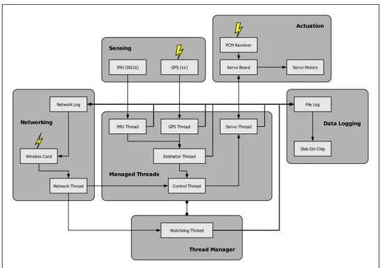
The new application architecture consists of a single process with multiple threads to acquire sensors data, process the acquired data and send commands to actuators, just like the old one. In addition, another thread is used for network communications, while a low priority thread is in charge to periodically check for the system integrity and recover from unexpected faults. (For details see Section 4.3)
Data Logging
IMU Thread GPS Thread Servo Thread
Estimator Thread
Control Thread Network Thread
IMU (DG16) GPS (xx) Servo Board
Network Log PCM Receiver Servo Motors Wireless Card Watchdog Thread Managed Threads Sensing Actuation Networking File Log Disk-On-Chip Thread Manager
Figure 4-1: On-Board User Application Architecture
4.2.1
Threads, Multi-Threading Issues
Most of the tasks the user application needs to perform are periodic in nature and as such their implementation has been designed mainly as a periodic thread, but enough flexible to allow also aperiodic tasks to be performed.
Most of the tasks, with the exception of purely computational tasks, also need to access system resources, like the file-system for log files or the serial ports for commu-nication with external devices, and so the implementation explicitly provides sections for acquisition or initialization of system resources and to properly release them when the task has completed execution (typically when the user application is stopped, but also in case of detected malfunctioning). Memory allocation is not typically an issue, as for speed reasons tasks usually prefer static over dynamic allocation, but it could be handled the same way.
All the tasks, sooner or later, have to exchange some information between each other, to get new data to work on, to communicate the results of some computations, or just to synchronize their execution. But some tasks, in particular those dealing with external devices, could have their execution unreasonably delayed, for example
while waiting for new data to arrive from sensors, and so we also need a way to monitor tasks execution and, in case they freeze or they just take too long, a safe way to restart them without causing dangerous side effects. This is achieved by using special thread synchronization classes and by using safely interruptible library function calls.
Thread Implementation
Let’s see in detail how tasks are implemented as standard POSIX threads using C++ constructs. A task is represented by a C++ class that interfaces to the POSIX threads library to provide a higher level of functionalities to the programmer:
• For implementers
A set of overridable methods to implement initialization/cleanup operations, aperiodic/period execution sections, recovery from unexpected faults
• For users
A set of methods to control thread creation/termination, current status, schedul-ing parameters
Initialization and cleanup operations for all the tasks are performed inside the main thread of the application. This simplifies the error handling, which is demanded to the program’s entry-point function, and provides explicit order of resource acquisi-tion and release operaacquisi-tions, a property that could be useful to resolve initializaacquisi-tion dependencies.
Aperiodic and periodic sections are effectively executed in a separate thread. Ape-riodic execution is provided as a preamble to peApe-riodic execution: once apeApe-riodic op-erations are completed the task implementer can specify whether the periodic section should be entered or the task can terminate. The operations inside the periodic sec-tion are automatically repeated until a terminasec-tion condisec-tion is satisfied or the task is aborted because of excessively delayed execution. No explicit timing is provided
inside the loop, but each task can choose its own way to implement periodic behavior, either using timer functions or directly synchronizing with external devices.
Communication with external devices in a multi-threaded environment is usually achieved by calling library or system functions with blocking semantic. This is the easiest way and offers minimal system overhead and fast responsiveness, but it also tightly links a task execution to the device output rate. To avoid prolonged or in-definite delays the thread can be canceled1 and an appropriate method is called by the class implementation. This method can be overridden by the task implementer to perform a safe cleanup, after which the thread is restarted.
The current execution status can be determined by calling two different methods. One reports whether the thread is executing the periodic or aperiodic section, while the other can be used by the thread manager to implement a software “watchdog” using an internal flag maintained by the class. This flag is automatically set at the end of every cycle of the periodic section and when the method is called the flag is tested and reset, so that by periodically calling the method you can discover delayed threads.
Once a blocked or delayed thread is detected we must find a safe way to cancel and restart it, without affecting the rest of the threads. So particular care should be taken during interaction with other tasks and that’s why we also provide high level synchronization mechanisms for task implementers.
Thread Synchronization
The classical way to share data among different threads is using mutual exclusion, but its non careful use could lead to undesired side effects. In particular, failing to release a mutual exclusion can leave the other threads waiting forever and in the worst case freeze the whole application. With this in mind, all the synchronization classes available to task implementers have been designed to enter the mutual exclusion just for the time necessary to make a local copy of the data. No other operations are
performed and no cancellation is allowed inside the mutual exclusion.
Two classes are provided for sharing data among threads. One simply wraps read and write operations into mutual exclusion sections, while the other also provides means to wait for new data upon reading.
A third class instead implements a message queue accessible by multiple threads, either for reading or writing, with optional non-blocking behavior on reading when empty. This is used in our application, for example, to dispatch messages coming from the network to the desired thread.
4.2.2
Watchdog and Managed Threads
The main thread of the application, beside performing initialization and cleanup operations for all the other threads, is devoted to monitor managed threads and process some requests arriving from the network. Threads are kept under control while they are executing their periodic sections and if they’re taking more time than expected the thread manager, that we implemented as another class, can stop them and let them start again.
The implementation uses a so-called “watchdog” approach: a state variable is maintained for each thread, it is set at the end of the periodic section and it is periodically checked and reset by the main thread. If the thread is too slow or its execution has been forcefully delayed by blocking operations (e.g. access to external devices), a stall condition is detected and as a countermeasure the thread is canceled and then restarted.
Under normal conditions some thread can still run too slowly for the application purposes even if hardware is operating correctly. This is due to the way threads are scheduled for execution on the CPU and is particularly evident in case of heavy CPU load or threads with long computations and few synchronization points. Since the operating system uses fixed priorities when scheduling threads, particular care must be taken in setting priorities and scheduling parameters. The current implementation worked well in our experiments and the user can fine tune several parameters that
affect thread execution, but there is actually no guarantee that this couldn’t become an issue when the user code changes, as there are no means to specify deadlines2 for
each task.
This kind of problems cannot be solved by our thread manager. QNX, as many other commercially available real-time operating systems, does not support specifying a deadline for a thread, but only uses fixed priorities. The system cannot guarantee that threads will be executed within the desired period: if the thread priorities or scheduling policies are not chosen carefully, some threads are forcefully delayed and the thread manager will try to stop and restart them constantly. This could also happen if the run-time of a thread exceeds its intended period and, obviously, the only thing you could do in such a case is optimizing the code for better speed or getting a faster CPU.
4.2.3
Utilities
A large part of the development also involved some auxiliary components to facilitate testing and development of application tasks.
Most of the tasks in the user application need to keep trace of the acquired data or the results of computations, especially during testing and debugging phases. This data can be recorded on the disk-on-chip device for off-line analysis or broadcast through the network for remote monitoring purposes. The software layer for user applications provides a simplified mechanism for logging acquired data to disk. Disk logs can be saved as text files, for immediate inspection or direct analysis in mathe-matical applications (e.g. Matlab), or as binary files for optimal disk space usage. A stand-alone command-line tool is provided to convert binary log files to their textual representation. (See Appendix B)
Most of the computational tasks also require to deal with linear algebra, vectors and matrices, and though hand-coded optimized calculations are often preferred for speed reasons, they are also error prone and time consuming for development and
testing. Available commercial or open-source libraries, on the other hand, though highly optimized and tested, usually contain a huge amount of code and are built upon dynamically sized data, while for most applications the dimensions of a prob-lem are fixed and statically sized data is usually preferable for speed reasons. This considerations led to the development of a custom class library for matrix algebra that provides the speed of statically sized data, ease of use and almost automatic error checking at compilation time. (See Appendix A)
4.3
The Datalog++ Application
All the architectural elements we have developed and discussed above can be seen in action in the current Datalog++ application, the renewed on-board software that was born from the re-engineering process of the old Datalog application (See Section
2.4).
4.3.1
Main Thread and Network Connectivity
The main thread, as we already stated, is responsible for proper initialization and cleanup operations that involve all the application tasks. It represents the only entry and exit point of the whole application, that runs for the programmed execution time. A first amount of time is left for the other threads to reach their regimen, while a cyclic section implements the software watchdog, processes commands coming from the wireless network (changes to configuration parameters) and sends status messages back to the network.
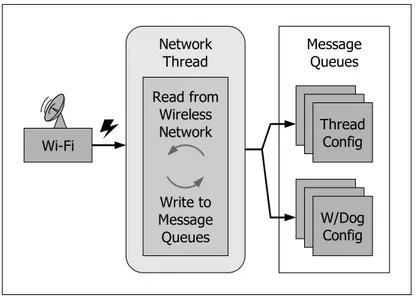
Remote commands are received from the wireless network by a dedicated thread that, like a demultiplexer, inserts each command in its own separate message queue, one for every command type. The network thread is not periodic in nature and as such it is not subject to the watchdog policy.
Any thread that needs to process remote commands can simply extract them from the respective queue. For example, the thread manager processes two types of remote
Main Thread
Wi-Fi
Shared Memory
IMU
Data DataGPS ControlState ServoCmd
Message Queues Thread Config W/Dog Config Initialization Cleanup Watchdog Free Run Managed Threads Network Thread
Figure 4-2: Main Thread
commands, one to change the management parameters of a particular thread (period of watchdog checks, frequency of status messages) and one to change parameters of the manager itself (execution time, frequency of status messages, etc) or to issue particular commands (anticipated exit).
Other command types may be added, along with their specific queue or shared memory slot. A queue is useful when we want to process all the commands received without time constraints. For example, changes to configuration parameters can be slightly delayed without undesired side effects. A shared memory slot can be used when the data arriving from the network has to be processed as soon as possible and we always want the newest data.
Note that the network thread only handles incoming messages. Outbound traffic is delegated to a separate component that supports access from multiple threads, so that each thread that wants to send messages through the network must do it independently from the others. And since it is a blocking operation, it has to account for it in its own computation time.
Network Thread Wi-Fi Read from Wireless Network Write to Message Queues Message Queues Thread Config W/Dog Config
Figure 4-3: Network Thread
4.3.2
Sensing and Actuation
The other application threads can be divided in sensing/actuation threads, dealing with external devices, and purely computational threads. All the sensing threads share the same fundamental structure and set of functionalities, while all the threads resemble the typical elements of a producer-consumer chain: they read, process and write data.
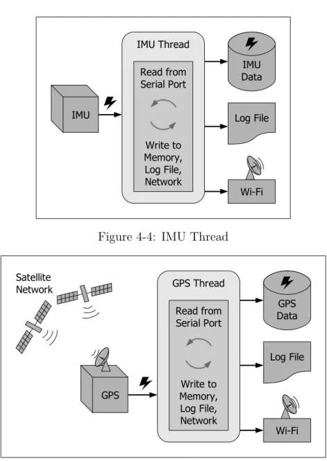
The IMU thread read angular rates and accelerations from the IMU using a serial connection. Data comes in binary format, packed in frames that are sent every 10 milliseconds. Higher resolution data is sent every second and it is reconstructed from ordinary frames every 100 frames. Both fast and slow IMU data is then logged to file and sent across the network, while only fast data is currently used for computations and stored in shared memory, after appropriate unit conversions.
Similar operations are accomplished by the GPS thread. The difference consists in the protocol used to communicate with the GPS device, which is now a single-line text-oriented format, and in the kind of data received. The device itself is much richer in functionalities and the intended output can be programmed in every aspect. The data currently in use is sent every 100 milliseconds and includes position, velocity and other precision indicators.
IMU Data Log File IMU IMU Thread Wi-Fi Read from Serial Port Write to Memory, Log File, Network
Figure 4-4: IMU Thread
GPS Data Log File Wi-Fi GPS Thread Read from Serial Port Write to Memory, Log File, Network GPS Satellite Network Figure 4-5: GPS Thread
operations. This completely synchronize the threads with their respective device, which gives them the constant rate they exhibit in their periodic sections and also the problems related to unexpected delays.
The servo thread has the double duty of capturing the pilot commands and send the computer generated commands. Synchronization is not implicitly provided by the serial communication and it is obtained with a system timer, that triggers thread execution every 20 milliseconds, matching the update rate of the servo-board.
Due to how the servo-board has been designed, computer generated commands are first sent through the serial port, then the received pilot commands are read,
Timer Servo Cmds Log File Wi-Fi Servo Thread Read from Memory, Write to ServoBoard Read from ServoBoard, Write to Log File, Network Servo Motors Servo Board Pilot
Figure 4-6: Servo Thread
4.3.3
Computational Threads
The estimator is composed of an initial phase to compute the bias in sensors data, followed by a periodic section to perform on-line state estimation, typically using variants of a Kahlman filter. The estimated state is logged to disk and sent through the network, while meaningful parts are stored in a shared memory slot for use by the control thread.
Control State Log File Estimator Thread Wi-Fi State Estimation IMU Data GPS Data Bias Estimation
Figure 4-7: Estimator Thread
provides the input for the control law, which is currently not implemented. The generated control commands are then stored to shared memory for use by the servo thread. These computer generated commands are logged by the servo thread along with pilot commands.
Servo Cmds Log File Control Thread Wi-Fi Control Law Control State
Figure 4-8: Control Thread
The control thread doesn’t currently produce a log file, nor it sends information across the network, but these functionalities may be required and implemented in the future, together with a control law. Also, controller inputs have been subsequently extended to include attitude estimation by horizon detection (see Section 6.2) per-formed on the ground station, requiring a new remote command message and a shared memory slot.
Chapter 5
On The Ground Solution
5.1
Goals And Requirements
During test flights and experiments with the UAV it can be nice, and often desir-able, to be able to communicate with the airplane in real-time, so as to early detect malfunctioning or incorrect behavior, or to easily modify some user application pa-rameters.
Other common operations performed during experiments, like transferring files to and from the UAV or starting the user application, were addressed with existing tools and technologies and are detailed at the end of this chapter. (See Section5.3)
The primary goals of our ground station were:
• Receiving and showing information about the current status of the on-board application, thus saving us the pain and the time to inspect the log files after each test or experiment
• The ability to remotely change some application parameters, without the need to recompile and upload the new code to the on-board computer, and the ability to send some high-level control commands to the plane
While the secondary objective was having a nice and easy to use graphical interface to the ground station functionalities.
The only requirement at this point, apart from the implicit requirements detailed in the second chapter (see Section 2.3), was to use the available wireless network we had working with the new disk-on-chip (see Section3.1). No requirements were made for the host computer or software platform.
This finally led our choice to the common and well known GUI development on the Windows platform with Visual C++ and MFC.
5.2
Design And Implementation
5.2.1
Network Communication
The first and most important aspect to consider was the network communication. Although the hardware problem had been solved, now the focus was on the commu-nication protocol to use.
Figure 5-1: OSI Layers [1]
The first choice to be made was about the transport protocol (see Figure5-1), that is the protocol that provides data transfer between two network hosts. The network protocol selected was naturally the IP (Internet Protocol), as by any means the most popular and supported on any platform. So, among transport protocols commonly
implemented over IP networks on most platforms, the alternatives were:
• TCP (Transmission Control Protocol
Implements a connection-oriented communication, providing a reliable data stream between two end-points. Suitable for transferring long chunks of data, but requiring some overhead to maintain a reliable connection (acknowledgment packets, retransmission).
• UDP (User Datagram Protocol)
Implements a connection-less communication, with no guarantees of actual data delivery. Suitable for exchanging short messages between two or more end-points, offers minimal system overhead.
Due to the nature of the communication between the ground station and the plane, that only involves small and sporadic status messages or commands, the UDP protocol1 seemed the perfect choice. This also allowed the plane to broadcast status
messages to the entire network, thus consenting multiple ground stations or other clients to receive and display the information sent, a feature that is especially useful in multiple vehicles scenarios.
Another aspect of TCP that makes it unsuitable for our application is how the connection is established and maintained2:
“The TCP must recover from data that is damaged, lost, duplicated, or delivered out of order by the internet communication system. This is achieved by assigning a sequence number to each octet transmitted, and requiring a positive acknowledgment (ACK) from the receiving TCP. If the ACK is not received within a timeout interval, the data is retransmitted.”
This means that, beside the network overhead for acknowledgment packets, a timeout wait is always present and prevents the use of blocking network primitives, thus losing all the advantages of TCP, like data delivery guarantee.
The next decision was about the application protocol (see Figure5-1), that is what kind of messages are involved in and how they should affect the communication. To this purpose we designed a very simple custom protocol, consisting of two types of datagrams:
• Messages
These are broadcast by the on-board application to any partner interested in receiving status information. Each task can have its own message format, that must be known to the receiver.
• Commands
These represent the data flow in the other direction, from the ground station to the plane. Each task can have its own command format, which is also implicit with the command.
Both messages and commands are sent in fixed-size packets, with the first field that discriminates among different types.
There are message types for every managed thread, that carry the same data that go to log files, but at a slower rate (currently every second). And there are two types of messages for the thread manager itself, one that provides status information about a particular thread, which is sent every second for a different thread in rotation, and one to provide up-to-date watchdog and global configuration parameters, like elapsed time since program start, which is also sent sporadically (currently every 2 seconds). Thread status comprise the current execution status – initialized, running, in-loop, alive – and other parameters, like the frequency of thread messages, or the period of watchdog checks.
Commands are currently limited to changes to some thread and watchdog con-figuration parameters, including requests to stop the on-board application before the programmed time elapses.
5.2.2
Software Architecture
The architecture is very simple: beside the usual message-pump thread, that runs the user interface, there is a secondary thread that receives network messages and sends them to the main window.
The network component reuses the same data structures and network code used by the on-board application, and as such particular care has been taken to provide a multi-platform network support. In particular, since both the plane and the ground station have a 32-bit Intel Architecture in hardware, numerical binary formats are the same, while we had to ensure the same alignment of fields inside structures, because we used different compilers.
Network messages, that arrives to the main application window as custom Window Messages, are then routed each type to a particular window, that is responsible to show them in the appropriate form to the user.
5.2.3
User Interface
The main window implements a tabbed-view or property-sheet, where each thread has its own page, a space where interacting with the user, linked to a corresponding tab. The user can switch between pages selecting the tabs at the top of the window. This kind of interface was chosen because of its simplicity and compactness.
Beside pages dedicated to managed threads, there is a page that displays the cur-rent application status and configuration parameters, and that also allows to change some of them.
In the Watchdog page we find two sections, one to show and modify individual thread parameters and another for global or watchdog related settings.
Thread execution status is shown with four green LEDs that indicates, in order from left to right: whether or not the thread has been successfully initialized, if it is currently running, if it is executing its periodic section, if it has been considered still alive from the last watchdog check. Then we find the number of restarts, the
Figure 5-2: Main Window - Watchdog Configuration
frequency of specific thread messages sent through the network.
In the lower section we find the programmed execution time, the period of status messages and the granularity of the watchdog cycle. This parameter specifies how often the watchdog has to wake up to perform a check, since it currently uses a polling approach and we need a mean to slow it down to give other threads CPU time. Note that when the watchdog is awaken it only checks those threads whose period is elapsed, otherwise it just goes back to sleep.
Figure 5-3: IMU, GPS, Estimator Data
Most of the other pages simply display numerical data, but visualization could be enhanced with any sort of graph that would keep trace of historical values.
Figure 5-4: Servo Board Data
shows pilot and computer commands using slider controls and battery voltage using progress bars.
No control data is currently sent by the plane and as such the corresponding page is empty.
5.3
Using The Ground Station
The ground station consists of a host computer meeting the following requirements:
• Wireless TCP/IP connectivity
• Win32 subsystem (native or emulated)
• UAV Station application
• ReadUavLogs utility (dove parlo di questa??)
• SSH/SFTP client
• NFS client (optional)
Once the on-board computer has completed the startup process, the user can connect the ground station to the plane using the SSH/SFTP client, upload the on-board application if an update is necessary, and then start the application in the background from the remote console. Background execution means that the application process is detached from the shell process that started it and so, when
the SSH session is closed (e.g. due to connection loss, which is likely to happen on a wireless network while the plane is moving), the application is not automatically terminated. Also, because the application prints a lot of diagnostic messages on the standard output and standard error devices, these should be redirected to the NUL device for better run-time performance, otherwise all the output would be transmitted through the network to the remote console. All this is easily implemented in a shell script which resides on the new disk-on-chip.
On the ground station, in the meanwhile, the user can run the UAV Station application and start monitoring task execution on the plane. Network messages usually don’t need to be sent at a high rate, they are just a mean to supervise the behavior of the on-board application and as such a rate of one message per second is usually enough and causes very little CPU overhead. This is the current default setting, that can be modified either by recompilation or at run-time by sending a particular command to the plane.
Once the experiment is complete the user can safely stop the on-board application using the UAV Station. Sending a termination signal to the application from a remote console is not recommended as it could not perform the appropriate cleanup operations (e.g. closing the log files).
After the on-board application has been stopped, the user can connect again with the SFTP client and copy the log files produced during the experiment to the local machine. If the application was configured to save binary files, then the user must run the log files through the provided ReadUavLogs utility to convert them to a CSV (Comma-Separated Values) text format. (See Appendix B)
Finally, text files can be imported in Matlab, or any other compatible application, for inspection, visualization and analysis. (See Section 6.1)
Chapter 6
Experimenting With The UAV
6.1
Testing The Platform
Throughout the development phase, of both the on-board software and the ground station, we tested our progress indoor, in our laboratory, and outdoor, especially after major advancements and before a real flight.
The plane had its “maiden flight” on November 2002 and another on March 2003, both before my arrival, with the old Datalog application and without the latest changes in the hardware configuration. The first flight went well, while during the second one something weird happened and the pilot lost control of the plane for a few seconds. After the flight the plane was analyzed and they found a floating screw that could have been at the origin of the malfunctioning.
After I joined the team, we had another two flight experiences, one failed and the other one successful.
6.1.1
First Flight
The first flight, after the new Datalog++ application development started, was sched-uled on June 2003. The day before we took the plane outside for a ride on the grass, so that we could verify that everything was ready for the flight.
the plane and found that it wasn’t responding to commands when he was standing farther than about thirty meters. We tried again turning off the on-board computer and this time the radio receiver could interpret the commands correctly at a greater distance.
So we thought we had an RF interference problem and we tried again several times with the computer on and progressively eliminating hardware components. We ended with the only main-board, CPU and memory, all the other devices (GPS, Wireless card, IMU) had been disconnected, and still the receiver had the same problems.
After spending many hours at the airport trying to figure out what could have happened, we had to give up and take the plane home, to run more extensive tests in the laboratory.
There we were able to measure the interference by connecting an antenna to our oscilloscope and we took all the usual countermeasures in these cases. We checked the internal connections and applied anti-inductive rings, we replaced the metal box for the computer with another one with less holes to improve shielding, we replaced the power regulator with a better one, we checked all the ground connections and replaced some with larger wires. But the interference, even if lower, was still there.
The we analyzed the radio receiver and we started testing the antenna position to find the best possible orientation. The final solution was to mount a mast for the receiver antenna, so that it could stand perpendicular to the plane and the computer box. This finally solved the problem and gave us enough range to fly safely.
6.1.2
Second Flight
The second flight was scheduled on September 2003, with small changes to the on-board software, but with a fully functional ground station. We also mounted a mini-camera on the plane to record in-flight video data for our horizon detection algorithm (see Section 6.2).
This time everything went as expected and the plane was engaged in plain and acrobatic flight for about 5 minutes, enough to gather the data we needed for model
identification and the horizon detection algorithm.
The Datalog++ application performed quite well, with only 4 restarts for the es-timator thread, that also had some numerical problems, and no restarts for the other threads. Anyway, the estimator code was still the same as in the old Datalog applica-tion and it had undergone several modificaapplica-tions in the past that made it difficult to track down the problem. The estimator has been rewritten using the new MatrixLib library (see Appendix A) and it still have numerical problems, but a new estimator is planned for the near future.
Another aspect to note is that the Wireless Network we established between the airplane and the ground station was very sensitive to the plane position and we experienced many black-outs in the connection, that was readily recovered however as soon as the plane was coming nearby.
6.1.3
Acquired Data
Here we report some graphs generated in Matlab from the log files we recorded in our last flight.
The first graph (Figure 6-1) shows that the GPS receiver could not report a valid position only in one case at the beginning of the flight, probably just before takeoff.
Figure 6-1: GPS Validity
Let’s see the position of the plane as reported by the GPS (Figure 6-2), expressed in local coordinates (the origin in the graph is where the recording started).
Figure 6-2: GPS Position
In the next graph (Figure 6-3) we plotted some accuracy parameters of the GPS, such as the four Dilution Of Precision indicators, the estimated device latency and standard deviation in the altitude indication.
Figure 6-3: GPS Analysis
We also calculated and displayed the time interval between consecutive GPS log entries. Although the device should be set to a 10 Hz output rate, we can see that the values seem to vary around an average of 140 ms, instead of the expected 100 ms, and we also have some high peaks around 300 ms.
threads, the higher average period can only have an external cause, such as the GPS device itself or the serial communication.
Passing to IMU data, again we have the time interval between log entries and the roll rate versus the aileron command from the pilot (Figure 6-4).
Figure 6-4: IMU Analysis
This time the average period of IMU data, 10 ms, is compatible with the expected output rate, but we still have a great variance and some spare high peaks.
The next two graphs (Figure 6-5) shows the battery voltage of avionics logic and servo-motors as measured by the servo-board. The exact unit of measure is currently unknown, but a fully charged battery is reported with values around 100.
We can see voltage drops in the motors battery throughout the recordings, with major concentration during the flight (in the right part) when the load was greater.
The last graph (Figure6-6) is the position calculated by an off-line estimator that resembles the one implemented on-board. It looks different from the first because of different axis conventions.
It is obtained using both GPS and IMU data, and an approximate dynamic model, originally for a plane with similar flight characteristics as our model aircraft.
Figure 6-5: Batteries Power from Servo Log
Figure 6-6: Estimated Position (off-line)
6.2
A Video Camera For Attitude Recognition
For this experiment the airplane has been equipped with a mini-camera that transmits a video signal to a radio receiver on the ground. The signal is then fed into a USB video capture device that we connected to the ground station, where it is sampled and processed for horizon detection. The results are then sent back to the plane through the wireless link as further inputs to help the state estimator.
Since the IMU provides accelerations and angular rates, we must integrate the accelerations twice to get position, and the angular rates once to get angles. IMU data
Log File Wi-Fi Frame Grabber Test Application Horizon Detection Algorithm On Board Camera Ground Video Receiver Frame Grabber DirectShow Filter Graph
Figure 6-7: Horizon Detection Application
is highly accurate, but has some very small error and since the error gets integrated too, it steadily grows larger and larger.
The error actually does not get very big during a five minute flight, but when we do the calculations for the estimator, we must subtract the acceleration of gravity from the acceleration measured by the IMU. If the estimated airplane attitude is even slightly incorrect, then when we subtract out gravity we leave in some component, which makes the system think it is accelerating in some direction. This adds to the IMU error and quickly causes the position estimate to become very inaccurate.
The horizon detection could give us an estimate of roll and pitch angles directly, without the problems coming from integrating angular rates, and could improve the whole state estimation.
6.2.1
Video Processing
The first problem to solve was how to acquire and process the video signal in real-time on the ground station. A quick research on the available technologies showed as, on the Windows platform, that we selected for the ground station, the most efficient and recommended way is using DirectShow, the component for video processing and display of the DirectX programming library. In some way it was also a forced choice, because the video capture device drivers were available only for Windows and Direct-Show. This is not an issue, though, since we also selected the same platform for our ground station.
![Table 4.1: Core Features: QNX Neutrino v6.2.1 [ 2 ]](https://thumb-eu.123doks.com/thumbv2/123dokorg/5638324.69501/22.892.136.776.216.817/table-core-features-qnx-neutrino-v.webp)
![Table 4.2: New Features: QNX Momentics [ 3 ]](https://thumb-eu.123doks.com/thumbv2/123dokorg/5638324.69501/23.892.138.774.283.909/table-new-features-qnx-momentics.webp)


![Figure 5-1: OSI Layers [ 1 ]](https://thumb-eu.123doks.com/thumbv2/123dokorg/5638324.69501/37.892.195.727.588.956/figure-osi-layers.webp)