1
School of Industrial and Information Engineering Master of Science in Mechanical
Engineering
ASSESMENT OF SEMISOLID PROCESS OF ALUMINUM ALLOYS
Advisor: Prof. Ing. Fabrizio D’Errico
Master Thesis by Chetan Venkatesh Babu,
ID: 900127
2
ACKNOWLEDGEMENT
The master’s study in Politecnico di Milano was the greatest experience and challenge in my life. I am grateful to all of those with whom I had the pleasure to work during the thesis and other related projects. I would like to take this opportunity thank our university for financially helping us through our entire course.
I would like to sincerely thank Prof. Fabrizio D’Errico for his valuable guidance, support and encouragement as supervisor which helped me greatly in the successful completion of this thesis work.
I am eternally grateful to my family, parents, and my siblings for who amid these years have supported me ethically and urged me to accomplish my dreams. This master’s degree would not have been possible without the support and guidance that I received from them.
Finally, we would like to say heartfelt thanks towards my friends Arpitha J S, Sowmya Lakshmi Mehganathan Vijayakumar, JVVSV Prasad, Kondepati Sudhir Kumar for providing me with unfailing support and continuous encouragement throughout the years of study and through the process writing this thesis. This accomplishment would not have been possible without them. Thank you
3
Abstract
Aluminium is one of the most excellent and popular metal which is significantly used in many
fields because of its higher properties. In order to improve its properties with the same
volume of material, new technology for metal forming is developed which is known as Semi
Solid Metal (SSM) process. SSM process uses solid-liquid slurries known as semisolid slurry
in which non-dendritic solid particles which is mainly globular solid particles are distributed
in liquid matrix. In the present decade, many processes for acquiring semisolid slurry for
obtaining non dendritic microstructures have been developed which is been discussed in
detail. Semisolid metal slurry exhibits distinctive rheological characteristics: the steady state
behavior is pseudoplastic (or shear thinning), while the transient state behavior is
thixotropic. SSM processing has established itself as a scientifically sound and commercially
viable technology for production of metallic components with high integrity, improved
mechanical properties complex shape, and tight dimensional control. Perhaps more
importantly, it has demonstrated its great potential for further technological development
and commercial exploitation. In this paper, progress made on the scientific understanding,
technological development, and industrial applications of SSM processing is reviewed.
4
Table of Contents
ACKNOWLEDGEMENT ... 2 Abstract ... 3 Table of Contents ... 4 List of Figures ... 5 Introduction ... 7 Chapter 1 ... 9Semi-Solid Metal Process ... 9
1.1 Rheology of Semisolid Metallic Materials ... 9
1.1.1 Rheological Classification of SSM ... 9
1.1.2. Semi Solid Behavior of Aluminum-Silicon slurries ... 11
1.2 Casting Process ... 13
1.2.1 Formation of Nondendritic Microstructures in SSM Processing ... 14
1.3 SSM Process ... 16
1.3.1. Technologies for Production of Nondendritic Feedstock ... 18
CHAPTER 2 ... 27
Methodology of SSM Characterization ... 27
2.1 Solidification Characterization ... 27
2.2 Alloy distribution and Solidification during SSM process. ... 30
2.2.1 Experimental Approach to Study Solidification and Alloy Distribution During SSM Casting ... 34
2.2.2 Alloy Distribution ... 36
2.2.3 Chemical Composition and Particle Size alteration due to Stirring. ... 38
2.3 Performance of Semi Solid Aluminum Alloys ... 39
2.3.1 Mechanical Properties ... 39
2.3.2 Fatigue Properties ... 40
2.4 Market Potential Overview ... 41
2.4.1 High Quality Casting ... 41
2.4.2 Improved Quality Die Castings ... 43
CHAPTER 3 ... 44
CONCLUSIONS ... 44
5
List of Figures
FIGURE 1 .A) GLOBAL ALUMINUM PRODUCTION SINCE 1900 TO THE PRESENT; THE AMOUNTS ARE EXPRESSED AS MILLION TON. (B) THE PRICE HAS NOT GONE DOWN WITH INCREASING AMOUNTS OF PRODUCTION IN THE LAST 3 DECADES, SUGGESTING THAT THE DEMAND IS ALSO INCREASING AND TAKING EVERYTHING PRODUCED.(C) THE PRICE IN DOLLARS IS SHOWN IN THE LOWER BLACK LINE (SAME AS IN (B)), AND THE RED LINE GIVES PRICE THAT IS INFLATION ADJUSTED
USING 1998 AS REFERENCE. --- 7
FIGURE 2. MICROGRAPH OF DENDRITIC AND GLOBULAR STRUCTURES IN A SEMISOLID ALLOY --- 8
FIGURE 3 SCHEMATICS OF A BASIC EXPERIMENTAL SETUP --- 9
FIGURE 4 VARIATION OF NEWTONIAN FLUID --- 10
FIGURE 5 VISCOSITY VS SHEAR STRESS OF SHEAR THINNING AND SHEAR-THICKENING FLUIDS --- 11
FIGURE 6 VISCOSITY VS SHEAR STRESS OF RHEOPECTIC FLUIDS AND THIXOTROPIC LIQUIDS --- 11
FIGURE 7 SCHEMATIC DIAGRAM SHOWING THE CHANGE IN VISCOSITY WITH TIME FOLLOWING CHANGES IN SHEAR RATE OF THIXOTROPIC BEHAVIOR OF SSM SLURRIES. --- 12
FIGURE 8 BILLET OF A SEMI-SOLID AL ALLOY BILLET CUT WITH AN ORDINARY KNIFE --- 12
FIGURE 9 DENDRITIC MICROSTRUCTURE OF AL ALLOYS --- 13
FIGURE 10 SCHEMATIC MODEL OF FRAGMENTATION MECHANISM: (A) UNDEFORMED DENDRITE, (B) AFTER BENDING, (C) DISLOCATION REARRANGEMENT TO GIVE GRAIN BOUNDARY, AND (D) GRAIN BOUNDARY WETTING --- 14
FIGURE 11 SCHEMATIC MODEL OF DENDRITE ARMS REMELTING. --- 15
FIGURE 12 INCREASE IN SHEAR RATE AND INTENSITY OF TURBULENCE CAUSE A CHANGE IN THE MORPHOLOGY OF PARTICLES; FROM DENDRITIC TO SPHERICAL, VIA ROSETTE, AND INFLUENCE OF SHEAR RATE AND SOLID FRACTION ON VISCOSITY - 15 FIGURE 13 SCHEMATIC REPRESENTATIONS OF SSM PROCESSES --- 16
FIGURE 14. SCHEMATIC DIAGRAM OF THIXO ROUTE. --- 17
FIGURE 15. SCHEMATIC DIAGRAM OF RHEO-ROUTE--- 17
FIGURE 16. DIFFERENTIATION OF THE THIXO AND RHEO TECHNIQUES. --- 18
FIGURE 17 SCHEMATIC DIAGRAM OF HIGH-TEMPERATURE CONTINUOUS MECHANICAL RHEOCASTER. --- 19
FIGURE 18 MICROSTRUCTURE OF A356 OBTAINED BY MECHANICAL STIRRING --- 20
FIGURE 19. SCHEMATIC OF ELECTROMAGNETIC COILS FOR MHD STIRRING AND SOLID PARTICLE FLOW PATTERN IN THE MUSHY ZONE --- 21
FIGURE 20 POLARIZED LIGHT MICROGRAPHS SHOWING THE EFFECTIVENESS OF EMS IN REFINING THE STRUCTURE OF A356 ALLOY CAST AT 850°C (A) WITHOUT STIRRING (B) EM STIRRED --- 21
FIGURE 21 PREPARATION PROCEDURE OF SLUG IN SEED PROCESS --- 22
FIGURE 22. MICROSTRUCTURE OF A356 ALUMINUM OBTAINED BY THE SEED METHOD. --- 23
FIGURE 23 EXAMPLES OF POSSIBLE CONFIGURATIONS FOR INTRODUCING FINE --- 23
FIGURE 24. SCHEMATIC REPRESENTATION OF THE STEPS IN THE GISS TECHNIQUE --- 24
FIGURE 25 SCHEMATIC DIAGRAM OF THE COOLING SLOPE TECHNIQUE --- 25
FIGURE 26. MICROSTRUCTURE OF A356 ALUMINUM AT 620°C OBTAINED BY THE COOLING SLOPE TECHNIQUE--- 25
FIGURE 27. SCHEMATIC ILLUSTRATION OF THE STAGES OF NEW RHEOCASTING (NRC) --- 26
FIGURE 28. MICROSTRUCTURE OF A356 ALLOY OBTAINED BY NRC METHOD --- 26
FIGURE 29. GRAPHITE CUP FOR THERMAL ANALYSIS --- 28
FIGURE 30 COOLING CURVE AND FIRST DERIVATIVE OF 356 ALLOY: (A) Α-AL FORMATION REGION, (B) EUTECTIC REGION --- 29
FIGURE 31 TYPICAL APPARENT VISCOSITY VERSUS FRACTION SOLID CURVE FOR SN15%PB ALLOY, COOLED AT 0.33°C MIN-1; (A) WITH A CONSTANT SHEAR RATE OF 200 S-1, (B) SHEARED CONTINUOUSLY AT VARIOUS SHEAR RATES --- 31
FIGURE 32. AL20%CU STIR CAST AT: (A) WITHOUT STIRRING, (B) 750 RPM, (C) 1000 RPM, AND (D) PARTICLE SIZE AS A FUNCTION OF STIRRER SPEED FOR AL24%CU --- 31
6
FIGURE 33 A SCHEMATIC ILLUSTRATION OF THE EFFECT OF FLUID FLOW ON THE BOUNDARY LAYER; (A) INFINITE (A) INFINITE BOUNDARY LAYER UNDER DIFFUSIVE TRANSPORT, (B) A FINITE BOUNDARY LAYER WITHOUT INTERDENDRITIC LIQUID PENETRATION UNDER LAMINAR FLOW, AND (C) EXTREMELY NARROW BOUNDARY LAYER WITH INTERDENDRITIC LIQUID
PENETRATION UNDER TURBULENT FLOW --- 32
FIGURE 34. SYNCHROTRON X-RAY MICROTOMOGRAPHY OF A DENDRITE WITH SOLIDIFICATION TIME --- 33
FIGURE 35. SCHEMATIC COOLING CURVE EXPECTED FOR STIRRED AND UNSTIRRED MELT --- 34
FIGURE 36 TYPICAL EXPERIMENTAL RESULT FROM CONTINUOUS STIRRING POURED AT 690°C --- 35
FIGURE 37 SCHEMATIC OF DIFFERENT THICKNESS OF BOUNDARY LAYER: A. UNSTIRRED MELTS, B. STIRRED MELTS. --- 36
FIGURE 38. SCHEMATIC REPRESENTATION OF THE BINARY DIAGRAMS FOR AL–SI SYSTEMS TOGETHER WITH CHEMICAL COMPOSITIONAL VARIATION IN A PRIMARY Α-AL PARTICLE, ASSUMING COMPLETE DIFFUSION AND MIXING IN THE LIQUID. [21] --- 36
FIGURE 39. SI DISTRIBUTION OF ALLOY SAMPLE 1 WITH STIRRED AND UNSTIRRED CONDITIONS [21].--- 37
FIGURE 40. SI DISTRIBUTION OF ALLOY SAMPLE 2 WITH STIRRED AND UNSTIRRED CONDITIONS [21]. --- 37
FIGURE 41. NUMBER OF ATOMS SOLIDIFIED AS A FUNCTION OF TIME UNDER DIFFERENT FLUID FLOW CONDITION ---- 38
FIGURE 42 FATIGUE STRENGTH DATA --- 40
7
Introduction
Aluminium (Al) and its alloy is one of the most popular nonferrous metal and is extensively employed by industries in numerous fields such as in automotive, civil, marine industries and also in many household utensils. Aluminium is the abundant metal in the Earth’s crust (8.1%) but is rarely found uncombined in nature. It is usually found in minerals such as bauxite and cryolite. These minerals are Aluminium silicates.
Because of rich resource, light weight, good mechanical properties, suitable corrosion resistance and excellent electrical conductivity and highly attractive hence there application have becoming more and more from the past decade. They also have high positive deciding factors for designers, manufacturers and industrial users, whose main goal is to have better-performing materials with innovative processes. The production of Al and its alloys are increasing in volume day by day due to its versatility, and its production is more than 29 million tons per year that is about 30 times more than the production in the year 1950 to present year and the forecast also predicts twice the expansion in production by 2050 this can be seen in the graph below.
Figure 1 .a) Global aluminum production since 1900 to the present; the amounts are expressed as million ton. (b) The price has not gone down with increasing amounts of production in the last 3 decades, suggesting that the demand is also increasing and taking everything produced.(c) The price in dollars is shown in
the lower black line (same as in (b)), and the red line gives price that is inflation adjusted using 1998 as reference.
Because of its high application, In January 2015, the European Commission issued the European Metallurgical Roadmap of 2050. Its long-term goal was to develop metals and metal-based matrix composites with high strength, high ductility, corrosion and wear resistance and to give priority to improve the strength, formability and corrosion resistance of 2, 5, 6 and 7 series aluminum alloys as well as to expand the use of heat-resistant aluminum alloys. In addition, high-strength aluminum alloy was listed as one of the key development plans in Advanced Manufacturing Partnership (AMP) of the USA.
8 With increasing demands for better mechanical performance of aluminum alloys, Scientists and researchers are coming out with numerous technologies for reaching higher strength as well as ductility of aluminum alloys. By several experimental analysis many scientists have come across that grain refinement and its microstructure were two key issues according to their outstanding effects on improving aluminum product’s mechanical performance. But grain refinement becomes a preferred method to improve simultaneously the strength and plasticity of metallic materials. The evident improvement brought by grain refinement is elevated strength at room temperature, which can be theoretically explained by the Hall-Petch relation.
σy = σ0 + ky*d-1/2
where σy is the yield stress, σ0 is a material constant of the starting stress for dislocation movement (or the resistance of the lattice to dislocation motion), ky is the strengthening coefficient (a constant specific to
each material), and d is the average grain diameter. Hall-Petch strengthening (or grain boundary
strengthening) is an important method of strengthening materials by grain refining; meanwhile, ductility is improved with increasing grain numbers.
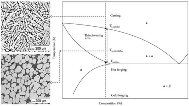
Scientists have also come across different techniques to obtain the non-dendritic microstructure that was initially developed by Fleming during performing an experiment in MIT. They came out by giving high shear to the metallic slurry at the temperature that is between solidus and liquidus temperature that produce a non-dendritic microstructure know has ‘SSM processing’. SSM-processing presents an alternative manufacturing route for aerospace, military and especially automotive components. Which we discuss in detail in this thesis. The Figure 2 shows us the phases and temperature required for generating non-dendritic microstructure from non-dendritic microstructure. So we can achieve high quality and defect free product.
9
Chapter 1
Semi-Solid Metal Process
SSM is one of the new manufacturing technologists that has wide spectrum of applications in many industries especially in Automotive industries. In this process metallic alloys are cast in the form of semi-solid slurry in the temperature range between liquidus and semi-solidus. The SSM slurry can be divided into two classes; Liquid like slurry that encompasses dispersed solid particles and behaves like a liquid under external forces, whereas the solid-like slurry encompasses an interconnected solid phase and behaves like a solid exhibiting a well-defined yield strength. SSM slurry contains 40 to 50 percent of solid fragments hence slurry can either flow like a liquid or can behave like a solid which is described by the rheological character of SSM
1.1 Rheology of Semisolid Metallic Materials
Rheology is the science that deals with flow of matter and deformation of solid. The rheological properties are responsible for the die-filling behavior of SSM that are unlike the fully liquid (or fully solid) materials. That are in turn depend on the viscosity, lower the viscosity better the flow of the slurry, this viscosity has the tendency to resist against deformation induced by shear stress These principles are explained with the help of Newton’s law of viscosity.
1.1.1 Rheological Classification of SSM
In 1687, Isaac Newton in the book ‘Philosophiae Naturalis Principia Mathematica’ (Latin origin book) has provided the information regarding the fluid flow and shear, among the other physical phenomena and postulated the idea of viscous fluid by with some basic experiments.
The experiment comprises, layer of fluid is confined between two metallic plates and are separated by the distance Y. Force (F) is exerted on the lower metallic plate hence it moves with the velocity (V) and assuming the flow is laminar, the layers of fluid close to the plate starts to flow and a time dependent profile is obtained. Later the force is kept constant we obtain the steady state velocity profile.
10 The arising shear stress is expressed by the Newton Law:
τ = -μ dudt (1)
Where:
• τ is the shear stress. • du
dt is the velocity gradient across the fluid layer and perpendicular to the direction of strain. • μ is dynamic viscosity of the fluid and depends on pressure and temperature
μ = μ (P, T) [Pa*s] Shear Stress can also be written in terms of strain rate
τ = μ γ͘ (2)
Equation (1) is called the newton’s law of viscosity. With the help of this equation we can see that the high viscous fluid requires higher stress in order to achieve same velocity gradient. Fluids which follows this equation are called Newtonian Fluid. The shear stress is proportional to the strain rate in Newtonian fluid.
Figure 4 variation of Newtonian Fluid
Fluid which does not follow this behavior are called Non-Newtonian Fluid. The rheological equation for this fluid is
τ = f (du
dt) (3)
Hence in Non-Newtonian viscosity is not dependent on shear rate and is not linear. These are further classified by
• Shear-thinning fluids (pseudoplastic) - viscosity decreases with increasing shear stress.
• Shear thickening fluids (dilatant) - viscosity increases with increasing shear stress
11
Figure 5 Viscosity vs Shear Stress of Shear thinning and Shear-Thickening Fluids
• Rheopectic fluids, that become more viscous over time when undergo shear
• Thixotropic liquids, that under the application of shear rate become little by little less viscous These fluids are dependent on time.
Figure 6 Viscosity vs Shear Stress of Rheopectic fluids and Thixotropic liquids
1.1.2. Semi Solid Behavior of Aluminum-Silicon slurries
SSM processing (manufacturing) is very important in forming and shaping characteristics of liquidus and solidus material. Commonly solid fraction in SSM slurry are about 50% which gives similarly characteristics of solid materials which can be easily shaped in die casting and frogging machines under high pressure because of the thixotropic characteristics of SSM billets having high viscosity at low stresses but a decreased viscosity when an increased stress is applied as shown in the graph below. In the graph we can see that the instantaneous viscosity is different from the steady state values, in order to reach the steady state condition it takes some time.
12
Figure 7 Schematic diagram showing the change in viscosity with time following changes in shear rate of Thixotropic behavior of SSM
slurries.
Visco-plastic nature of the semisolid slurry depends on the amount of solid fraction it contains and determines the feasibility of shaping it in the form of components. The viscoplastic behavior of SSM materials is mostly assessed by rheological tests with viscosity as the main physical parameter for characterizing the slurry. Viscosity and deformation behavior of matter establishes the correlation between its rheological and mechanical behavior of Al-Si Slurry.
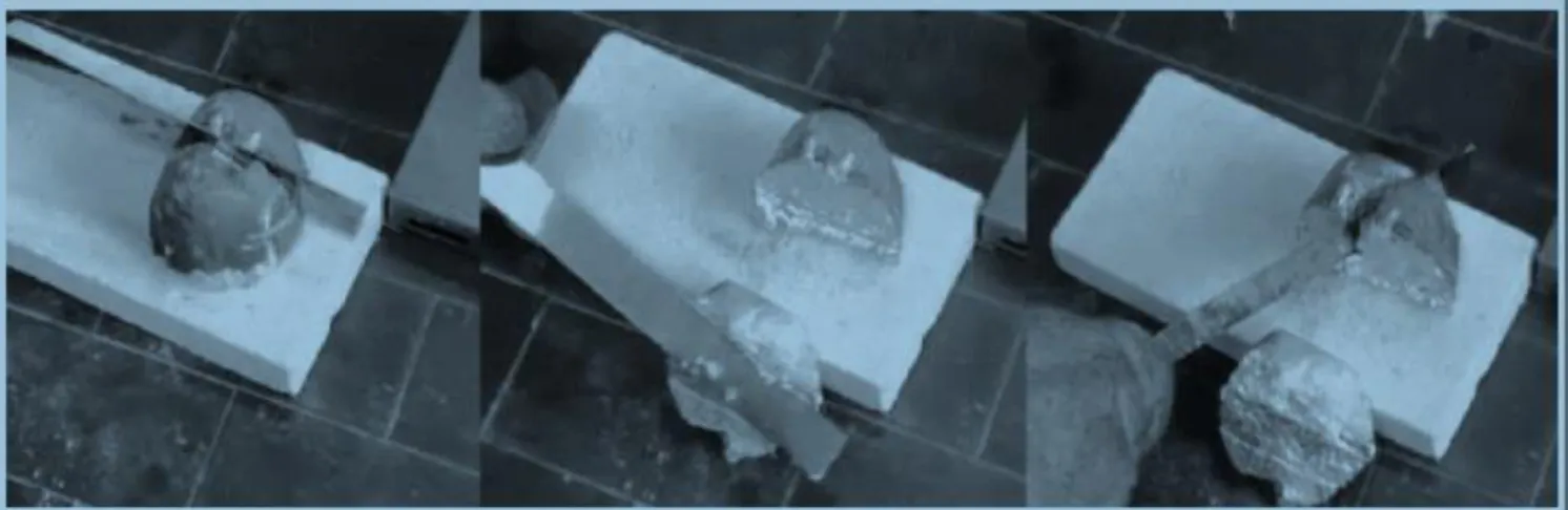
SSM containing higher solid fraction exhibits high yield stress. That is shown in the Figure 8 below where the Al alloy in semi solid state able to wear out due to its own weight and can cut with the ordinary knife.
13
1.2 Casting Process
At the solidification temperature atoms from the liquid molten metal begins to bond together and starts to form crystals. The movement of crystals starts to grow and the point where it starts is known as nucleation. In metals crystals that form in liquid during solidification that resembles like a pine tree which is known as dendrite. In polycrystalline material many dendritic crystals forms and grown enough to impinge upon each other. The dendritic growth mainly results in macro-porosity and micro-shrinkage due to the gas evolution during the solidification process. These defects mainly affect the fabrication process as it weakens the mechanical properties of the Al alloys.
Figure 9 Dendritic microstructure of Al alloys
To overcome this problem Semisolid metal processing was established which has both scientifically and industrial importance in forming and casting process because of its improved mechanical and die filling properties. These SSM process produce non-dendritic microstructure, globular equiaxed structure, due to shearing of metal alloy slurries as it is cooled from the liquid state. These globular microstructures produce lower porosity and avoid shrinkage voids. These casting process has lower processing temperature and less mold erosion with higher die life. Like most conventional high pressure die casting, semisolid process can accomplish near net shape and minimizes secondary machining costs. SSM processing can also be used to cast thick materials whereas the conventional process casting of thicker and larger parts is very difficult as the amount of heat energy required to be extracted during solidification is very high and this reduces the life of the die.
The globular microstructure obtain in SSM process are homogeneous. The viscosity of the SSM slurry is higher than when fully liquid slurry this lessens the risk of turbulent or spray flow, which is more typical of conventional pressure die-casting. With the help of shear thinning phenomena of the slurry, due to the effect of a shear force acting on it when it flows into the die, the viscosity decreases and the metal slurry fills the die completely in a nonturbulent manner.
14
1.2.1 Formation of Nondendritic Microstructures in SSM Processing
In most SSM processes are carried out by induced fluid flow or “forced convection”. According to Fleming and co-workers, in the initial stages of solidification the metallic materials has the dendrites form in the liquid state. Unlike conventional solidification, the shearing action affects the dendritic morphology, which changes into that of a “rosette” due to different phenomena. Numerous explanations about the conversion mechanisms from dendritic to globular morphology can be performed by ripening, shear, bending and abrasion with other growing crystals but the main mechanisms are dendrite fragmentation, remelting of dendrite arms, and growth control mechanisms.
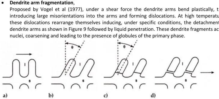
• Dendrite arm fragmentation,
Proposed by Vogel et al (1977), under a shear force the dendrite arms bend plastically, thus introducing large misorientations into the arms and forming dislocations. At high temperatures these dislocations rearrange themselves inducing, under specific conditions, the detachment of dendrite arms as shown in Figure 9 followed by liquid penetration. These dendrite fragments act as nuclei, coarsening and leading to the presence of globules of the primary phase.
Figure 10 Schematic model of fragmentation mechanism: (a) undeformed dendrite, (b) after bending, (c) dislocation rearrangement to give grain boundary, and (d) grain boundary wetting
• Dendrite arm root remelting mechanism,
According to Hellawell et al (1996), the secondary dendrite arms can separate at their roots owing to solute enrichment and thermo-solutal convection that determines because of solute enrichment and thermo-solutal convection that determines their remelting rather than breaking off for simple mechanical interactions as shown in the Fig 9. He suggested that in the solidification range, the solid is completely ductile and dendrites can be bent but not broken. Hence, the detachment of the secondary arms can be explained by a local remelting phenomenon. In particular, the remelting can occur either by recalescence of the whole system or by local recalescence due to fluctuations caused by convective phenomena or stirring.
15
Figure 11 Schematic model of dendrite arms remelting.
• Excessive nucleation mechanism
Is a thermally activated mechanism where localized undercooling is artificially generated within the bulk liquid to accelerate nucleation. From the solidification point of view, if the mean free path between the nuclei becomes small due to excessive nucleation, grains grow slowly due to limited constitutionally super cooled boundary layer and multidirectional heat flow. Such solidification conditions should eventually lead to the formation of more or less spherical primary phase particles. Excessive nucleation-based processes could be preferable because of elimination of at least one step and subsequently shorter processing time and better globule morphology.
The effect of the fluid flow characteristics on the morphology of solidification structures was also studied, by means of Monte Carlo simulation, by Das et al. They found that a rotational motion under laminar flow promotes rosette-like morphology due to a periodic stabilizing and destabilizing of the solid–liquid interface, while a turbulent flow hinders dendritic growth resulting in a compact morphology due to a stable solid–liquid interface. The presence of a concurrent mechanism was also proposed.
Figure 12 Increase in shear rate and intensity of turbulence cause a change in the morphology of particles; from dendritic to spherical, via rosette, and Influence of shear rate and solid fraction on viscosity
16
1.3 SSM Process
The SSM manufacturing process has been extensively studied and has become one of the important applications in many industries. It is the combination of both casting and forging, having huge number of advantages over conventional processes. This process has the advantages of both liquid and solid forming processes.
However, the input for semi-solid processing, the phenomenon of thixotropy, was discovered about a half century earlier, in 1923, by Schalek and Szegvari in a non-metallic system. They found that aqueous iron oxide gels would become completely liquid through calm. Previously, these kinds of physical changes had only been known to occur by modifying the temperature when gels would melt on heating and then re-solidify on cooling.
The main advantages of SSM process we know that metal is not being held in the liquid state over long periods of time and the production rates are similar to pressure die casting or better. Lower processing temperatures reduce the thermal shock on the die is reduced because processing temperature is very less that promotes higher die life and allowing the use of non-traditional die materials. Obtained uniform microstructures has enhanced properties like reduced solidification shrinkage gives dimensions closer to near net shape and justifies the elimination of machining steps.
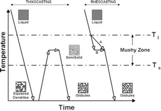
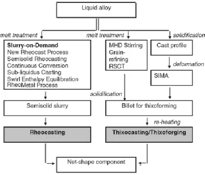
Familiarity of various routes and having the perception of formation of slurries so we can choose the optimum and most appropriate process for any application. This chapter deals with the principles in the SSM studies including an overview of different processing route. SSM methods can be divided in two main categories according to their processing route, known as ‘Rheocasting’ and ‘Thixocasting’.
17 Thixo-route or Thixocasting process was the first commercially viable source for semi-solid processing and it is a three-step process that begins with a cold billet of appropriate length that is formed by the ‘Thixoforming’ process and it is reheated at the temperature to obtain the desire solid fraction before injecting it into the mold cavity. The cost of the Thixocasting process made less importance in usage in industries when compared to Rheocasting process.
Figure 14. Schematic diagram of Thixo Route.
Rheo-route or Rheocasting involves in preparation of SSM slurry directly from the liquid alloy, subsequently a forming process such as High Pressure Die Casting (HPDC). With ‘Rheo’ processes the alloy is cooled into a semi-solid state and then is introduced into a die with no intermediate solidification step; semi-solid slurry with non-dendritic solid particles is produced from a fully liquid regular alloy. It is cooled to obtain the desired fraction solid and then it is cast into a part. This process is more cost efficient when compare to Thixo-route as there is no in intermediate step hence many industries implement this process.
Figure 15. Schematic diagram of Rheo-route
In the initial era of the commercialization of the SSM casting process, thixocasting process had a highly capable of preparing slurries with excellent rheological characteristics. Regardless of good process control ability in thixocasting, but a high degree of industrialization has not been achieved due to the cost of the preformed thixoformed billet and the incapability to recycle the scrap. Hence rheocasting because of the lower investment cost has developed promisingly. However, most of the rheocasting processes depend on two distinct mechanical and thermal-based processes for SSM preparation. That is temperature control where heat is extracted from the surrounding which is cooler, and simultaneously applying the shear force necessary to prepare the slurry.
18
Figure 16. Differentiation of the Thixo and Rheo techniques.
1.3.1. Technologies for Production of Nondendritic Feedstock
As discussed above, production of feedstock with thixotropic properties is a key step for successful SSM processing. In addition we have seen that SSM technologies are divided into two main categories based on the starting material status: (1) either from a liquid alloy through controlled solidification (by activating crystal multiplication of a growing solid or by increasing the nucleation rate) under specific conditions, or (2) from the solid state through heavy plastic deformation and recrystallization. Number of techniques have been developed from past decades and it is still developing. These techniques are mainly responsible for the formation of final microstructure hence to obtain with higher properties. The most effective methods, as well as those most commonly used in commercial practice, are described briefly below.
1.3.1.1. Agitation process
A. Mechanical Stirring
The implication of stirring during solidification of alloys was initially originated at the Massachusetts Institute of Technology, MIT. This process involves in vigorous stirring of the metal slurry with the help of augers or screw, impellers, paddles, or some special kind of agitators where the molten slurry is in the holding vessel as shown in the Figure 17. The process was advanced from batch into a continuous process. Where the feedstock from this method can be used directly in the semi-solid slurry state for near-net shaping of parts through the rheocasting route. The vigorous agitation of the superheated molten metal during solidification is responsible for the deformation and melting of dendrite arms that go to form equiaxed grains in the liquid matrix. These grains will remelt due to the surrounding bulk liquid that still
19 contains small areas of superheated liquid within it and there will be little quantity of particles which still exists in the molten metal. These exceptional particles are developed after taking the temperature out of the molten metal for a preset value of time to solidify them into fine and non-dendritic microstructures. We can obtain very fine globular microstructure in liquid matrix with high solidification rates in conjunction with high shearing rate. Slurry flows from the bottom of the rheocaster either to be cast directly to shape (rheocasting) or to be solidified as feedstock material for subsequent reheating and thixoforming.
Figure 17 Schematic diagram of high-temperature continuous mechanical rheocaster.
Regardless of mechanical stirring being the first SSM processing technique, there are many limited applications on industrial scale due to its drawbacks such as erosion of the stirrer (particularly with more chemically aggressive alloys), the contamination of the slurry by oxides and dross, gas entrainment, low productivity, and the difficulty in process control. In addition, slurries produced by such processes tend to contain larger, ripened rosette particles and less homogeneity than other processes.
20
Figure 18 Microstructure of A356 obtained by mechanical stirring
Figure 18 shows the rheological process performed at the temperature 587°C for A256 billet by S. M. J. ALVANI (10.1016/S1003-6326(09)60376-9) by using mechanical stirrer, where they obtain morphologies immobilize and entrap more liquid, adversely affected the rheological behavior of the slurry by reducing the effective liquid fraction.
B. Magneto Hydro Dynamic (MHD) Stirring or Electro Magnetic Stirring (EMS)
In order to overcome the disadvantage that is encountered with direct mechanical stirring, International Telephone and Telegraph (ITT) in the USA developed the magnetohydrodynamic (MHD) stirring process that produces non-dendritic alloys. The local shear is engendered by a dynamic electromagnetic field and the solidifying metal is the rotor. The stirring action resulted from liquid movement shears the dendrites causing the dendrites’ fragmentation during the process. Hence this process overcome the gas entrapment in the slurry to a minimal and there is the reduction of contamination in the slurry. We can also filter the slurry and degas it, which generates large quantities of fine-grain feedstock material, which is typically around 30μm performed at fast process speeds and of consistent repeatable quality. Due to its many advantages this process becoming more and more important in commercial applications.
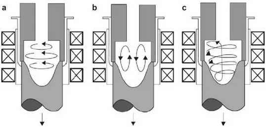
There are three modes of electromagnetic stirring capable of achieving vertical, horizontal, and helical fluid flow shown in Figure 19.
In the vertical agitation mode, the dendrites near the solidification area undergo convection transfer to the hotter zone to remelt and the globularization mechanism is controlled by thermal processing rather than mechanical shearing.
In the horizontal agitation mode, the motion of the solid particles is held in an almost isothermal plane and the globularization mechanism is controlled by mechanical shearing.
The helical mode is a combination of the vertical and horizontal modes. In the horizontal flow mode, solid particles are moved in a quasi-isothermal plane so that mechanical shearing is more likely to be the leading mechanism for dendrite disintegration
21
Figure 19. Schematic of electromagnetic coils for MHD stirring and solid particle flow pattern in the mushy zone (a) due to rotational inductive coils, (b) due to linear inductive coils, and (c) helicoidal stirring.
Figure 20 shows billets cast with and without application of EMS with a very large superheat of about 230°C. By continuous and uniform cooling parallel to dendrites fragmentation and spheroidization during EMS process, it seems that the process is reasonably capable for structural evolution. Even though this method is an improvement on mechanical stirring, there are still some problems, such as solid particles forming rosettes that are not completely round and the nonuniformity of the microstructure in the cross-section of the casting billet leading to increased reheating times. The production cost increases as a result of these problems, and the extra steps involved in feedstock production, as well as in actual processing of parts because of the reheating of feedstock necessary prior to forming into parts, and the difficulties of recycling the non-dendritic gates, off-cuts, and other scrap in situ, made the MHD route an expensive one.
Figure 20 Polarized light micrographs showing the effectiveness of EMS in refining the structure of A356 alloy cast at 850°C (a) without stirring (b) EM stirred
22
C. Swirled Enthalpy Equilibration Device Process
The Swirled Enthalpy Equilibration Device (SEED) process is a method for feedstock preparation for semi-solid forming processes patented by ALCAN International in 2002. In order to have regular temperature between the mold and bulk the liquid metal in metallic mold is stirred off-center at certain RPM.
This process is split up into three stages to produce required slurry, as shown in Figure 21.
• In the first stage low superheat is applied to the metal at a uniform temperature above the liquidus temperature followed by pouring the melt into a vessel (for heat extraction). After which the vessel and its contents are rotated at preset rpm, this rpm depends on features of the mold and the mass of the charge. The swirling action assists in ensuring that the solid phase is generated and several nucleation locations at the vessel surface are formed.
• In the second stage, the swirling motion is stopped, and after a brief pause of 5–10 s the bottom plug is removed to allow some remaining liquid to drain. The degree of superheat and the swirling and drainage time and speed are selected in such a way as to allow a solid fraction of 0.3–0.4 to form before drainage. This is based on heat exchange between the mold and molten alloy.
• The last step is performed after a specific time between 30 and 45 s, the prepared billet is unloaded and transferred into a high-pressure diecasting machine to fabricate the finished products.
Figure 21 Preparation procedure of slug in SEED process
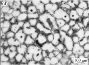
The swirling action aids in provides nucleation at several locations of nucleation at the surface and with the help of a slow cooling process to prevent the growth of dendritic arms. The microstructure of A356 aluminum obtained by the SEED method is shown in Figure 22. Two parameters should be taken into account to ensure success when casting ingots via this technique. First, the intensity of stirring, and second, the pouring temperature. These parameters directly affect the range of structures from dendritic to globular and the microstructural evolution.
23
Figure 22. Microstructure of A356 aluminum obtained by the SEED method. D. Gas Induced Semi Solid process
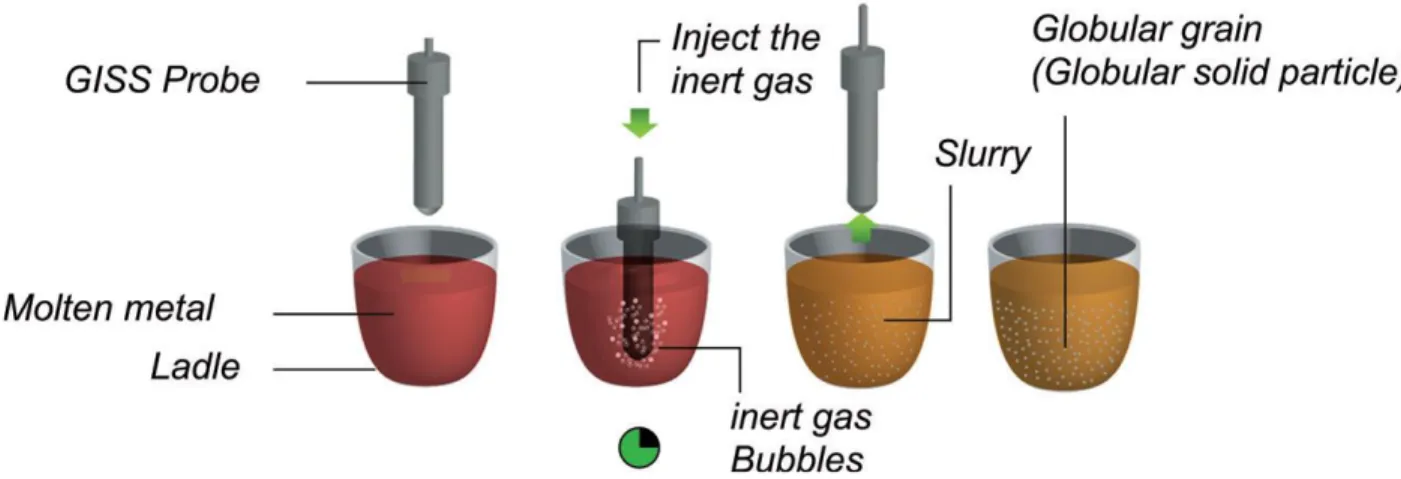
Gas-induced semi-solid (GISS) technique is a novel approach in rheo-casting process proposed by the Innovative Metal Technology team at the Prince of Songkla University, that utilizes the principle of rapid heat extraction and vigorous local convection using the injection of fine gas bubbles through a graphite diffuser in molten metal we can obtain non-dendritic microstructure. The injection gas are mainly argon or nitrogen gas. These gasses also cools down the molten metal to semi solid range. The fine gas bubbles can be introduced in different configurations into molten metal in the gas-induced semi-solid (GISS) process as shown in the Figure 23.
Figure 23 Examples of possible configurations for introducing fine
The preparation of the slurry can be broken down into three steps in this method, as shown in Figure 24. • In the first step, that starts by applying low super heat at a uniform temperature at a predetermined amount
at a temperature near or just above the liquidus temperature of the metal.
• In the second step, a porous graphite diffuser is then injected into the melt introducing inert gas bubbles. • In the last step, the diffuser is withdrawn and the semisolid metal slurry is inserted directly into the casting
24
Figure 24. Schematic representation of the steps in the GISS technique
The mechanism of dendrite fragmentation for this technique can be explained as follows: the cold graphite diffuser is immersed in the melt, and the low superheat temperature causes numerous fine dendritic grains to nucleate and grow on the diffuser's surface. The flow of gas bubbles enables these particles to be speedily extracted into the melt. These fine grains remelt due to the surrounding bulk liquid which still contains small areas of superheated liquid within it. Only a small amount of particles continues to exist in the molten metal. These particles further develop by removing heat out of the melt for a predefined time to obtain fine, non-dendritic microstructures. The GISS route is suitable for processing different types of alloys such as zinc alloys, cast aluminum alloys, wrought aluminum alloys, and die casting aluminum alloys.
1.3.1.2. Non-Agitation Process
A. Cooling Slope
Application of cooling slope is a widespread practice for semi-solid slurry production. The cooling slope technique is the simplest non-agitation process that produce near-globular solid fraction in a liquid matrix. This process is a continuous casting process. The heat is applied to the metal to maintain the constant temperature at the temperature near to or just above the liquidus temperature. The slurry is made to flow above the cooling slop and later it is collected in a mold, or it can be used directly in combination with a shaping process such as rolling. The cooling slope process is shown in Figure 25.
25
Figure 25 Schematic diagram of the cooling slope technique
The mechanism of dendrite fragmentation for this technique is based on crystal separation theory. Initial nucleation of granular crystals starts at the contact surface of the cooling plate, and due to movement of the fluid above the cooling plate which is accelerated by gravity, the nucleation on the slope wall removes the molten metal into a heating mold, thus ensuring that the spheroid size is fine and the microstructure of A356 aluminum poured at 620°C and produced by the cooling slope method is shown in Figure 26. This type of process is not desirable for all applications for the following reasons: gas interruption, contamination of the slurry by the chemical reactions and oxidation, and difficulty of controlling the process. The principle variables that have a direct effect on the microstructure are the length and angle of the cooling slope, the molten metal superheating, and the material of the die.
26
B. Liquidus Casting
Liquidus casting, also known as a New Rheocasting (NRC) or low superheat casting, was developed as a low-cost alternative non-agitation technique for thixotropic feedstock production. In this process low level of superheat is enforced on the metal and maintaining a uniform temperature above the liquidus temperature. After that the molten metal is poured into the holding mold and there for the preset value of time so that molten metal can be conditioned into slurries of fine, non-dendritic microstructures that can be charged into the inclined sleeve of a vertical squeeze casting machine, as shown in Figure 27
Figure 27. Schematic illustration of the stages of New Rheocasting (NRC)
The mechanism of dendrite fragmentation is as follows. The pouring of the superheated molten metal into the holding vessel is responsible for deformation and melting of the dendrite arms. The grains will remelt due to the surrounding bulk liquid that still contains small areas of superheated liquid within it. Nucleation takes place in the melt where only a small amount of particles continues to exist and these particles develop into fine, globular microstructures after the melt is undercooled for a predefined time, as shown in Figure 28.
Figure 28. Microstructure of A356 alloy obtained by NRC method
Two issues should be deemed to ensure success when casting ingots using this technique. First, the melt superheat should not exceed 10°C, and second, the solidification speed of the molten metal has a direct effect on the shape of the initial crystal structures.
27
CHAPTER 2
Methodology of SSM Characterization
Conventional solidification of hypoeutectic Al–Si foundry alloys takes place with dendritic formation of primary α-Al phase within the liquid. The alloy composition, temperature gradient within the melt, thermo-fluid convection, and rate of heat extraction and the resulting constitutional supercooling are the most effective parameters on the morphology of the primary α-Al phase. Variation of any of these factors during solidification would alter the as-cast structure. For instance, introduction of agitation (forced convection) into the solidifying melt changes the distribution of alloying elements and localized chemical composition, could remove constitutional supercooling, and promote dendrite-to-equiaxed transition, i.e., break down and globularization of the α-Al phase. Degeneration of the α-Al phase results in some opportunities which are of interest from commercial viewpoints.
The term “characterization” covers a wide range of thermal, mechanical, and microstructural analytical techniques used to evaluate physical, mechanical, and metallurgical parameters of SSM billets and finished products. The SSM billets are often required to be examined for their solidification pattern, rheological behavior, and microstructure. The outcome of such studies helps in understanding / predicting the fluid flow and die-filling behavior of the SSM billets along with the possible mechanical and load-bearing characteristics of finished product.
2.1 Solidification Characterization
The excellence of finished product is bind up with the excellence of feedstock (billets). The SSM processing parameters is responsible for the veracity of the billets and these are inferred on the solidification condition as discussed earlier. Information on the nucleation and transformation from the liquid to solid phases depends on the cooling curves. The characterization and monitoring that should be followed for the alloy solidification is explained in this chapter.
In order to obtain the cooling curve for the aluminium alloy the standard tests are performed for an instance, experiments performed by the Backerud et al. and Tuttle [46, 47]. The molten alloy is prepared in resistance heating furnace by melting pure Al-Si ingots and degassing using argon. Molten material was poured into graphite cups of 25 mm inner diameter and 5 mm wall thickness as shown in Figure 29. Cups were held inside the crucible for approximately 1 min prior to tests to reach equilibrium condition ensuring uniform temperature distribution across the sample at the beginning of solidification. Each cup with ~50 g of alloy was transferred to the testing platform and two K-type thermocouples (0.8 mm diameter) was quickly immersed into the melt near the center and wall of the mold with their tips at 10 mm from the mold bottom. Temperature readings was collected by a high-speed high-resolution data acquisition system (National Instrument SCXI- 1102) at ten readings per second sampling rate. To ensure the radial heat flow, insulating plates was placed above and below the sample cup. To improve data consistency and reproducibility, the same thermocouples was used for all tests by placing the thermocouples in a 1 mm (inner diameter) stainless steel sheath. The protective sheath saved thermocouples after solidification where they could be easily removed from sample and reused.
28
Figure 29. Graphite cup for thermal analysis
It is very difficult to obtain the cooling rate above liquidus temperature or in the mushy zone. Nevertheless, the cooling rate is often registered high right after mold filling due to initial rapid heat dissipation. The cooling rate gradually slows down in the mushy zone. As an example, they used cooling rates for the graphite molds between 1.5 – 2 °Cs-1 above liquidus temperature and 0.5 – 0.6 °Cs-1 in the mushy zone. The analysis of the thermal data was carried out following Backerud et al. and Tuttle [46, 47]. ( Figure 30) indicates the cooling curve for Al-Si alloys used in graphite cups.
❖ Tnuc Al: Start of primary α-Al dendrites nucleation
❖ TminAl: Unsteady state growth temperature, the temperature beyond which the newly nucleated crystals grow to such extent that the latent heat liberated surpasses the heat extracted from the sample
❖ TgAl : Recalescence of steady-state growth temperature due to release of latent heat of primary α-Al dendrites
❖ ΔTRec: Temperature difference between unsteady (TminAl) and steady (TgAl) state growth temperatures of primary α-Al particles (recalescence)
❖ tRec: Recalescence time, time difference between TminAl and TgAl , the times associated with TminAl and TgAl
❖ Tnuceut: Start of eutectic nucleation
❖ Tmineut and Tmaxeut : Minimum and maximum of eutectic temperatures ❖ Δθ: Variation of eutectic recalescence (Tmaxeut _ Tmineut)
❖ Tend: Solidification termination
❖ ΔTα: α-Al solidification range (TnucAl _ Tnuceut) ❖ ΔTeut: Eutectic solidification range (Tnuceut _ Tend)
29
30 Mathematically undercooling is the difference between TminAl and TgAl, where TminAl defined as the starting point of solidification. According to the Backerud et al. [46] the actual solidification starts above the TminAl and it is detectable by the first derivative (∂T∂t ) curve as shown in the Figure 30. The change in the slope of ∂T
∂t is an indication of energy change in the system and the only energy change during solidification is the formation of solid phase, start of nucleation. So if the solidification start is the point shown in Figure 30, undercooling is an integral requirement to trigger nucleation and to onset solidification. The actual undercooling may be defined as the difference between the equilibrium melting temperature (perceptible from equilibrium phase diagram) and the TnucAl. Therefore, the value of (TminAl - TgAl ) is neither undercooling nor nucleation range and can only be defined as the recalescence range.
Percentage of the alloying elements in the melt varies the results of the cooling curve. For an instance, the liquidus temperature of the Al–Si melts varies with Si% according to the following equation [48]
T1(°C) = 662.2 – 6.913*[%Si]
So, by a simple calculation, it is evident that a compositional difference of 0.1% Si between two samples means a difference of about 0.7 _C. Hence the chemistry variation is a key in the cooling curve analysis.
2.2 Alloy distribution and Solidification during SSM process.
As we know that solidification of hot alloys with the stirred condition produces nondendritic structure. Numerous scientists have come across with many experiments in order to explain the solidification oat semi solid process. Spencer et al (1972). performed experiments to investigates the relation between the viscosity and solid fraction. He measured the viscosity of Sn15%Pb alloy as a function of solid fraction through repeated shearing of the alloy by using an equipment, rotational rheometer. Spencer et al. came to the result that unstirred melts began to show strength around 0.2 fraction solid (20 %), by stirring the resulted slurries continued to behave like a liquid beyond 0.4 fraction solid (40 %) as seen in Figure 31.a. Joly and Mehrabian in 1976 carried out further investigation of Spencer in 1972 on the rheology of the same alloy. They came to the conclusion that the viscosity is not only dependent on the solid fraction but also varies by cooling and shearing rates as shown in the Figure 31.b. They also confirmed that increasing the shear rate induces morphological transition at shorter times and results in less liquid entrapped within the primary particles.
31
Figure 31 Typical apparent viscosity versus fraction solid curve for Sn15%Pb alloy, cooled at 0.33°C min-1;
(a) with a constant shear rate of 200 s-1, (b) sheared continuously at various shear rates
Vogel et al. in 1979 performed experiments on the rheological behavior on Al–Cu alloys and he states that in the dearth of stirring, the alloy has conventional dendritic structure but transforms to rosette-like particles when stirring is introduced with the help of mechanical impeller. The rosette morphology will further transform to spherical particles as the rotational speed is increased as shown in Figure 32. It was also observed that the maximum particle size decreases by increasing the stirring speed.
32 In 2002 Das et al. explains the growth morphology of dendrites with the help of computer simulation and he states that it is highly dependent on the nature of fluid flow as shown Figure33.That is, In a pure diffusive flow, i.e., absence of flow in the liquid, solute transfer takes place by diffusion through approximately the entire volume of liquid, as if, there is an infinite diffusion boundary layer and the resulted growth structure is purely dendritic Figure 33.a. Figure 33At low and intermediate shear rates (Figure 33.b.), the flow is laminar
with a finite boundary layer existing around the growing particle beyond which the melt has homogeneity. It has been shown that the introduction of forced convection causes destabilization of the solid/liquid interface and enhances dendritic growth from a fixed substrate. Das et al.’s result agrees with the theoretical stability analysis of Vogel et al. except that the model developed by Das et al. predicts destabilization only under laminar flow condition and for solid particles growing from a substrate
Figure 33 A schematic illustration of the effect of fluid flow on the boundary layer; (a) infinite (a) infinite boundary layer under diffusive transport, (b) a finite boundary layer without interdendritic liquid penetration under laminar flow, and (c) extremely narrow boundary layer
with interdendritic liquid penetration under turbulent flow
Hellawell et al in 1996 also gives the information on the crystal multiplication during solidification where he suggested that the refinement of the microstructures in stir cast processes in not solely depended on the mechanical interaction where it also depends on the temperature fluctuation. He also gives the explanation that the slurry is completely dendrite and ductile near the melting temperature. Hence it can be easily bent elastically or plastically depending on the amount of shear given by the mechanical stirring. This shear does not fractures the dendrite but it only detaches the side arms by the phenomenon of a local remelting phenomenon.
33
Figure 34. Synchrotron X-ray microtomography of a dendrite with solidification time
In 2009 Limodin et al. explains the morphology and microstructural evolution during solidification with the help of an experimental setup using the synchrotron fast X-ray microtomography performed on Al10%Cu alloy at a constant cooling rate of 3 K*min-1. The X-ray microtomography produces 3D images of the
dendrites of AL alloy during its solidification. He noted in different cooling temperature and its time as shown in Figure 34. In his observation he noted that on the left-hand side of the dendrite the roots between adjacent arms (1–5) progressively filled with solid and the tips of the adjacent arms grow until they touch and join each other. Another phenomenon is dissolution of arms 10, 12, and 15 from the tip toward the roots to the benefit of larger adjacent arms, i.e., remelting mechanism. Due to recalescence there may be vigorous nucleation. The vigorous stirring prevents the establishment of stable diffusion fields necessary for dendrites evolution. Also multiple nucleation exists due to periodic passage through different temperature zones. Eventually, smooth rounded shapes are expected out of solidification.
In the subsequent chapter it gives the details in illustrating the effect of stirring on the solute redistribution and solidification pattern of 356 Al– Si alloy in the frame of process specification. It also contents different hypothesis in order to obtain the best structural evolution for SSM process.
34
2.2.1 Experimental Approach to Study Solidification and Alloy Distribution During SSM
Casting
In order to analysis the effect of SSM casting process we need to compare the process with the conventional casting process with the SSM casting process. That is various tests which are performed with the stirring and without stirring by many researchers. In order to find the effects of stirring the alloy is stirred in different angular velocity about 1.5-2.5 Hz to obtain the semi solid structure.
As we know that solidification of any material follows two steps that is the formation of nucleation and the growth of it. Similarly the SSM follows the same pattern which is explained in detail below.
A. Nucleation of Stir-cast material
The nucleation which is the active mechanism to initiate primary α-Al usually takes place on foreign particles such as refiner, inclusions, oxides, and especially mold wall where the molten alloy was poured onto the mold wall to reduce turbulence. As we discussed in the previous topics as the shear is increased on the SSM slurry, columnar dendrites which starts at the surface of the mold will be fragmented and by the forced convection the broken parts of dendrites are mixed with the bulk liquid. By the solute enrichment and thermal solutal convection also is responsible for the detachments of dendrites arms. As we contemplate heterogeneous nucleation, the size of nuclei and boundary layer is critical and should be consider. According to hypothesis of Hellawell (1996), the critical size of nucleus will be far below the thickness of boundary layer around the moving particles. With stirring, these particles will be swept away with their small boundary layers and these nuclei alter the recalescence during solidification and it causes continuous fluctuations in the local temperature as suggested in Figure 35 and Figure 36 shows typical cooling curves for samples cast with and without stirring which appears to support the aforementioned hypothesis.
35 As shown, the assumption of Hellawell (1996) based on continuous nucleation appears to be correct. The authors just want to add that in the stirred sample, nucleation of primary particles is not only continuous, but also with stirring nucleation temperature shifts up. As indicated by arrows, forced convection increases the nucleation temperature by more than 6°C. This value in the case of alloy distribution is quite important since by increasing the solidification commencement temperature, the liquidus curve is also moved up which could lead to a different composition as will be described later. It is interesting that there is no registered recalescence exists which is believed to be associated with improved heat transfer with agitation. Therefore, a longer nucleation event could mean more nuclei forming within a definite time, i.e., extensive nucleation, resulting in a refined structure
Figure 36 Typical experimental result from continuous stirring poured at 690°C
B. Stir-Cast Growth
When the slurry is cooled by the natural convection without any stirring effect then the distribution of the liquid solute is found out by the diffusion field only and we obtain the tree-like structure of crystals usually know as dendrites at the nucleation site and it grows by means of columnar or equiaxed morphology. But the phenomenon in the stirring effect changes completely, there is complete uniform distribution of the solute because of the forced convection given to the solute by the stirrer. There is the reduction of the thickness of the stagnant boundary layer that is formed around the primary particles (Figure 37). This is caused due the thermal solutal homogenization due to stirring and there is the suppression of heat flow direction. The morphology of the grain becomes smother and more equiaxed as the columnar grain growth is gradually eliminated. Above the boundary layer the concentration of the solute is controlled by the convection field. Additionally, the liquid becomes warmer because of vigorous agitation and it trims off the tip of columnar dendrites and it stimulates the formation of equiaxed structure in the stir cast parts. The so-called globule particles will eventually form with further stirring. Furthermore, due to vigorous agitation, no stable diffusion field can be formed and therefore growth would be sluggish in all directions, i.e., rounded refined structure.
36
Figure 37 Schematic of different thickness of boundary layer: a. Unstirred melts, b. Stirred melts.
2.2.2 Alloy Distribution
To realize the effects and the distribution of alloy in SSM materials of Al alloys we need to analysis the experiments performed by S. Nafisi et al. in 2006 [21], They performed several analyses on Al-Si alloys to know the distribution of the alloys and the effects of the alloys with and without stirring during solidification. With the varying the percentage of the alloying elements we can easily distinguish the grain or globular boundaries. With the help of the phase diagram of Al-Si shown in the Figure 38 we can see the decrease of the Si in the center of α-Al when compared to its edges. The primary phase of the first solid solution that is formed just below the liquidus is purer than the subsequent solid layers. Which means as the temperature is lowered it increases the solubility of the alloying element with the primary then there is more solubility of the α-Al particles as for instance for silicon, it reaches 1.65 wt% at eutectic temperature. [21]
Figure 38. Schematic representation of the binary diagrams for Al–Si systems together with chemical compositional variation in a primary α-Al particle, assuming complete diffusion and mixing in the liquid. [21]
37 To get more understanding S. Nafisi et al. in 2006 [21]. performed the microprobe analysis of two alloys with different silicon concentrations and compared with the stirred and unstirred alloys. They summarized as show in the Figure 39 and Figure 40. As we know that the primary α-Al has the tendency to soluble with the maximum of 1.65 % weight of Si at the eutectic temperature, indicated in the binary Al–Si phase diagram (with different alloying system and cooling rate the limit of solubility of Si may vary).
The nature of alloying system is the solute accumulation. The boundary layers formed from the atoms of the solute has different composition from both solid and liquid. When the partition coefficient k is less than 1 in the binary phase diagram then the solute is rejected into liquid so the first solid is purer than liquid. As the temperature decreases the adjacent solid layer will be marginally rich in solute. This sequence proceeds until the liquid becomes richer in solute after which the solidification takes in the lower temperature.
Figure 39. Si distribution of alloy sample 1 with stirred and unstirred conditions [21].
If there is no diffusion in the solid then the separate layer of solid will contain the original compositions. Hence the original composition of the solid will always have the low composition when compared with the solid liquid interface which can be easily seen in the Figure 39 and Figure 40. These figures show the percentage of Si in the α-Al particles and it is quite clear that the first solid, center of Al cell, is always purer than the others. Furthermore, the Si concentration at any point across the primary α-Al particle varies with and without stirring. It is quite important to note that all line scans were collected for specimens poured and quenched at same temperatures.
38
2.2.3 Chemical Composition and Particle Size alteration due to Stirring.
1. Modification of Chemical Composition during stirring
At the higher temperature, nucleation in stir cast solidification commences when contrasted to conventional unstirred samples. Thus, according to the phase diagram, the first solid to form is more depleted in solute, e.g., with less silicon concentration. This is obvious through Figure 39 and Figure 40 showing less silicon concentration in stirred samples. If the phase diagram does not shift the same way as the nucleation temperature, then such conclusion is correct. Since, the solidus and liquidus lines movement are not clear, the concept is described in term of fluid flow and boundary layer concentration. As deliberated, the solute concentration will gradually disappears when convection is applied at the solidification front and thus the next solid to form is not as rich as expected from phase diagram or the unstirred alloy.
Figure 41. Number of atoms solidified as a function of time under different fluid flow condition
Studies performed by Fan and coworkers [45], they reported that the theoretical stir growth in the alloys is not identical to that of the experimental one. Using Monte-Carlo based simulation, they came up with the result that growth enhancement occurs under pure laminar flow, but when the flow becomes pure turbulent, there is progressive growth retardation occurring as compared to pure diffusive flow Figure 41. In contrast to laminar flow that has greater growth probability, for turbulent flow the growth rate is initially high due to the faster transport of solvent atoms but gradually retards with the progress of solidification.
39
2. Particle Size alteration due to Stirring
In semi-solid casting of hypoeutectic Al–Si alloys, the morphology and size of the eutectic silicon are important parameters affecting the mechanical properties of the as-cast products. In addition, the chemistry of the billet with respect to impurities and alloying elements such as Fe, Mn, Cu, Zn, Mg, and Ti may result in some complications in the microstructure due to the formation of intermetallic phases. For instance, iron is one of the most common and perhaps the most significant alloying or impurity elements in Al–Si alloys; either added intentionally to mitigate certain characteristics such as soldering or die sticking or otherwise as an unwanted impurity. The Fe addition imparts two distinct features; on one hand, it forms different intermetallic together with Al and Si, with most of them regarded considerably harmful to the mechanical properties of the finished product and on the other hand, it reduces the interaction of molten aluminum alloys with permanent molds, i.e., soldering or die sticking, due to the formation of a thin layer of intermetallic at the interface between the die and the castings during solidification.
2.3 Performance of Semi Solid Aluminum Alloys
In the modern era, several studies have been fixated towards the mechanical properties of parts fabricated by semi-solid processes and they have been compared with the conventional routes. This will provide information about the heat treatment that should be considered for semi-solid castings.
2.3.1 Mechanical Properties
Often semi-solid castings are produced in the T5 temper. This heat treatment eschews the issues correlated with blistering during solution heat treatment, a problem that is not experienced by castings produced by gravity poured or low-pressure processes. T5 heat treated Semi-Solid aluminium alloys are the premium products in the present market. Table 1 shows the mechanical properties of A356 alloy. In the table we can see that mechanical properties of T5 casting of A356 is significantly lower than the conventional process.
Process Heat-Treatment .2% YS (MPa) UTS (MPa) Elongation (%)
Rheocast T5 180 270 7
Rheocast T6 235 310 13
Sand T6 207 278 6
Permanent Mold T6 205 285 10
Table 1 Mechanical property data for alloy A356 [49]
Hence it is necessary to perform T6 heat-treatment to further increase their characteristics. There are also many scientific studies on the mechanical properties of Al SSM alloys (both casting and wrought ones), even though significantly less than those on microstructural modification in comparison with conventional casting alloys.
Process Alloy Heat-Treatment .2% YS (MPa) UTS (MPa) Elongation (%)
Rheocast 319s T6 340 400 8
Permanent Mold
319 T6 165 250 2
40 Alloy 319s, is one of the best semisolid cast which has very high significant mechanical properties than the conventional casting process which can be seen in the Table 2. Alloy 319s has the nomenclature or the composition Al6.0%Si-3.0%Cu-0.35%Mg, is the primary version of the low-cost foundry alloy 319. As shown in Table 2, the mechanical properties of semi-solid cast 319s-T6 are significantly better than permanent mold cast 319-T6, and in fact except for the difficult to cast Al-Cu alloys [49], the 319s-T6 alloy exhibits mechanical properties that cannot be achieved by any other conventional foundry alloy. Alloy 319s, therefore, may provide a niche for semi-solid casting.
2.3.2 Fatigue Properties
Data measured by the Cummins Turbo Technologies indicated in the Figure 42, which is summarized by conducting the tests for several alloys produced by casting, forging and semi-solid casting. Figure 42 shows that, not only are the fatigue properties of semi-solid cast alloy is appreciably better than all of the cast alloys examined by Cummins (including high strength alloy 206), but they are comparable to samples produced by forging from wrought alloy 2618. They confirmed the fatigue behavior by functional fatigue testing performed with cast, forged and semi-solid cast impellers.
Figure 42 Fatigue strength Data
To encapsulate the properties of Semi-Solid casting alloys, to produce higher static strength of semi solid casting it should be heat treated at T6 Temper. However, that casters must utilize lubricants and die filling parameters that minimize blistering, and while the amount of research on blistering of semi-solid castings is limited, researchers at the General Research Institute for Non-ferrous Metals have recently examined parameters that minimize blistering. In addition, while the strengths of conventional alloys (A356, 357) produced by semi-solid casting are not significantly higher than components produced by conventional foundry processes, elongation values are higher. In addition, alternate alloys (319s, 206, wrought alloys) can also provide significant benefits. Components that are used in fatigue applications should also be considered for semi-solid casting.
161
153
100
87
Semi Solid Cast A356-T6 Forged 2618-T61 Cast A354-T61 Cast A355-T61
Fati gu e S tr e n gth at 107 C yc le s ( M Pa)