8 ANALYSIS OF UV ABLATION
OF CARBON FIBER
REINFORCED PLASTICS
The use of laser technology for cutting and drilling of CFRPs is attractive in the production field since the use of a contactless removal technique can avoid the main drawbacks of the conventional machining processes already mentioned in chapter 3: rapid tool wear and mechanical stresses on the composite which may cause delamination. However, the large differences in material properties of the carbon fibres and matrixes adopted present serious challenges to the laser-based process. The issues related to heat affected zone (HAZ) causing charring and potential chemical degradation have been the major obstacles for its industrial applications.
The recent progress in laser system technology enables innovative techniques for machining of CFRPs. Different wavelengths and pulse duration have been tested showing that the combination of modern UV-laser sources with a scanning technology enabling deflection speeds up to 2m/s, suppresses heat affected zones (HAZ) and detachment of fibers from the polymer matrix. A representative application of this laser set-up is represented by the drilling process as well as the layer by layer removal of damaged composite material. Results carried out with a layer by layer technique show that it is possible to achieve a fast and reliable removal rate which enables to perform holes and arbitrary cavity geometries in CFRP laminates. A method for the selective removal of surface matrix without damaging the fibers beneath is also presented.
107
8.1 INTRODUCTION
Carbon Fiber Reinforced Plastics (CFRPs) are gaining wide acceptance in the aeronautic sector, for the excellent strength-to-weight ratio offered by the laminates.
As reported also in chapter 3, the machining of composite laminates after the forming process, is frequently practiced due to the need of assembling different parts by bolted or riveted joints when is not possible to obtain complex structures by a single forming process. As second aspect it should be considered that the brittle nature of the fibers combined with the very low toughness of the thermoset resins conventionally used as matrix, makes CFRP sensitive to dynamic loads and surface wear [1]. During service life CFRPs laminates also undergo to damage coming from accidental impacts or hydraulic fluids absorption. Thus, structures maintenance and repair is the concern of end-users as well as manufacturers. The laminate repair is a further mechanical removal process obtained by manual grinding of the damaged part and by refilling the obtained cavity with a patch of new plies.
As a matter of fact, it is demonstrated that the wide introduction of CFRPs in the aeronautical production led to need of additional machining processes which are significantly affected by the tendency of these materials to delaminate and the fibers to bond from the matrix under the action of machining forces.
Delamination, fibres pulling out, matrix chipping, heat damage and rapid tool wear generally represent the main concerns during the machining process of long-fibres composites. These difficulties inspire the use of alternative machining technologies with the twofold objective of achieving high cutting speed and product reliability and at the same time preventing the damage of the material.
Lasers, as non-contact and wear-less machining tools, exhibit unique advantages in processing such anisotropic and inhomogeneous materials. Nevertheless the fact that polymers used as matrixes are characterized by vaporisation temperature and thermal conductivity of one or two orders of magnitude lower than carbon fibers [2], typically lead to extended thermal damages. A challenge in laser processing is to minimise the heat affected zone (HAZ) in which matrix is melted or even burned and fibers are thermally degraded, retaining at the same time high processing speed.
8.2 LASER MACHINING OF CFRPs
Lasers have been often proposed for machining of composites over the past 30 years. First experiments on laser machining of CFRP laminates have been conducted in the 1980s with common IR sources: studies were conducted on CO2 and Nd-YAG lasers focusing on the analysis of the material removal mechanism during cutting [2,3]. Further researches were devoted to the optimization of process parameters [4] also making use of predictive models aimed at reducing thermal damages [5,6].As a matter of fact these wavelengths induce a large Heat Affected Zone (HAZ) due to the fast conduction along the fibers which degrades the matrix and reduce the interlaminar integrity of the laminate. Nevertheless Herzog et al. [7] recently studied the influence of HAZ on the residual static strength of CFRP laminates cut with IR power-lasers. Authors demonstrated that these sources could represent a valid alternative for cutting but, as thermally acting tools, are not
suitable for engraving purposes. As far as the drilling process with Nd-YAG laser Voisy et al. [8] reported that a further defect due to the large heat input on the composite is represented by fibers swelling. A chemical degradation of the reinforcements increase delaminative effects.
High process qualities, such as reduced HAZ and charring as well as matrix recession due to extended thermal conduction, are then major drawbacks for the application of industrial lasers, as reported in [9].
First approaches to laser engraving of CFRP were then undertaken in the 1990s [10] using UV-wavelengths. Excimer lasers were used to minimize the thermal effect and for a precise energy deposition. It has been shown that HAZ of only 5– 30 µm could be obtained for several material types, including uni-directional laminates. Unfortunately even if results obtained by excimer lasers were very promising, the very low process speed, due to the reduced pulse repetition rate (200-500Hz), hindered the industrial use. Furthermore, the deployed imaging technique with fixed masks limited the flexibility of the process and the availability of the total output power.
Such drawbacks are now overcame by a new generation of diode pumped solid state (DPSS) lasers in which the beam quality allows an efficient frequency doubling and tripling using non-linear crystals. In this way green-laser (532nm) and UV-laser (355nm) radiations can be generated with short pulses (typically between 15 and 50ns), and combined with high repetition rates of 200-300kHz and a Gaussian beam profile of very high quality factor (M2 < 1.2). Völkermeyer et al. proved [11,12] that with these UV-lasers it is possible to obtain a very detailed ablation mechanism based on the direct sublimation of the irradiated material along with a negligible HAZ.
8.3 UV-ABLATION OF CFRPs
Main characteristics of the ablative process are represented by the photon energy which depends on the wavelength used and by the dynamic aspect in which the pulse is released.
The high energy (3.49eV) of photons generated by a third-harmonic DPSS laser (355nm) combined with the ultra-short pulse duration generates a vigorous expulsion of material on the surface due to the breaking of chemical bonds which constitute the structure of the plastic matrix and fibers. This phenomenon known as cold ablation is mainly due to the photochemical action of the laser radiation: the dynamic impact of laser pulses hinders heat transfer to the workpiece and the ns-pulse duration transforms a relatively low average beam power to a peak-pulse intensity in the GW/cm² regime able to remove both fiber and matrix. As a result ablation is confined to the narrow area of impact ensuring excellent resolution and high edge quality without a remarkable development of HAZ.
Ablation can be also obtained with longer wavelengths (532nm and 1064nm) which generate lower photons energy (respectively 2.33eV and 1.16eV). Especially in case of 1064nm wavelength, thermal transfer to the workpiece is relevant since photons energy, which is not enough for bond-breaking, excites the chemical structures causing internal friction. In this case a reduction of the pulse duration (e.g. using the ps or fs regimes) is desirable since it decreases the time for thermal transfer.
109 The material removal in the ablation process is frequently argued as reported by Sato and Nishio [13]. Authors suggested that both photochemical and thermal mechanisms, the last due to energy release by excited molecules, contribute to the etching process. The etched depth per pulse (Dtotal) is then given by the sum of two terms Dphotochemical and Dthermal:
⎟ ⎠ ⎞ ⎜ ⎝ ⎛ − + ⎟⎟ ⎠ ⎞ ⎜⎜ ⎝ ⎛ = RT ED A ED ED D th th total ln exp 1 α (1)
where ED is the energy density [J/mm2], α the absorption coefficient [mm-1] and EDth the threshold energy density. The second term (1) which reflects the influence of the plasma cloud on the surface should be inserted in equation for ED>>EDth. At higher ED these effects become significant and derive from the Arrhenius law, being A [mm] a constant depending on the process boundary conditions, T [K] the temperature, and R the gas constant.
Starting from this theoretical consideration the ED threshold values of an innovative thermoplastic matrix (Polyether-etherketone PEEK) and carbon fibres, were determined experimentally. The use of PEEK as matrix in the aeronautical field provides an improvement of wear resistance of the laminate. Furthermore this it offers excellent mechanical and chemical resistance and keeps these properties up to remarkably high temperatures (150°C) [14]. A 355nm laser with a repetition rate of 90 to 300kHz was used for this first series of experiments. The pulse duration of the output beam ranges between 15ns and 30ns depending on the repetition rate. In this way it was possible to determine the range of variation of process parameters with the twofold objective of quick fibre machining and reduced HAZ on the polymer matrix. Carbon fibres can be retained totally absorptive and independent on the wavelength.
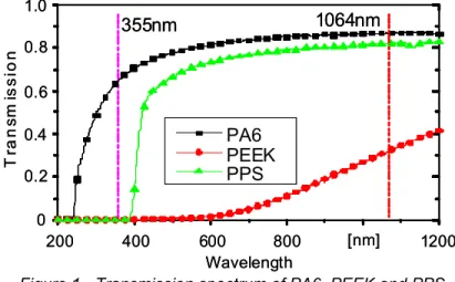
Figure 1 - Transmission spectrum of PA6, PEEK and PPS.
Polymers reflectivity is also negligible while energy lost due to transmission through the material can be significant. This is shown in figure 1 where the percentage of transmission is plotted for different wavelengths. PEEK is generally more absorptive respect to other thermoplastic materials commonly used as matrixes
T rans m is s ion Wavelength [nm] PA6 PEEK PPS 355nm 1064nm 200 400 600 800 1200 0.2 0.4 0.6 0.8 1.0 0 T rans m is s ion Wavelength [nm] PA6 PEEK PPS 355nm 1064nm 200 400 600 800 1200 0.2 0.4 0.6 0.8 1.0 0
(nylon PA6 or Polyphenylene sulfide PPS) and offers very high absorption especially in the UV region.
Experiments have been carried out ablating grooves on a thin PEEK film and on a pure fibers lamina, perpendicularly to their orientation. Results plotted in figure 2 show the dependence of the groove depth (measured by a 1 µm resolution optical microscope) on the increasing of ED calculated as follows:
spot scan average V P ED φ = (2) being Paverage the output power given by the laser source at a fixed frequency, Vscan the scanning speed and Φspot the diameter of the spot once focused the beam on the specimen surface (25µm for the experimental set-up used).
Figure 2 - Groove depth on PEEK film and CF lamina versus energy density, at a fixed pulse repetition rate of 90kHz.
0 5 10 15 20 25 35 0.50 0.55 0.60 0.65 0.70 0.75 0.80 0.90 CF lamina [J/mm2] 0 5 10 15 20 25 35 0.55 0.60 0.65 0.70 0.75 0.80 0.90 CF lamina [J/mm2] Energy Density 0 0.005 0.010 0.015 0.020 [J/mm2] 0.030 PEEK film [µm] 0 5 10 15 20 25 [µm] 35 De p th 0 0.005 0.010 0.015 0.020 [J/mm2] 0.030 PEEK film 0 5 10 15 20 25 [µm] 35 De p th De p th 0 5 10 15 20 25 35 0.50 0.55 0.60 0.65 0.70 0.75 0.80 0.90 CF lamina [J/mm2] 0 5 10 15 20 25 35 0.55 0.60 0.65 0.70 0.75 0.80 0.90 CF lamina [J/mm2] Energy Density 0 0.005 0.010 0.015 0.020 [J/mm2] 0.030 PEEK film [µm] 0 5 10 15 20 25 [µm] 35 De p th 0 0.005 0.010 0.015 0.020 [J/mm2] 0.030 PEEK film 0 5 10 15 20 25 [µm] 35 De p th De p th
111 The pulse repetition rate represents a further relevant process parameter since it determines the pulse overlap for a given scanning speed. For the laser source adopted the maximum Paverage of 23W was obtained with a frequency of 90kHz. Values of Vscan [1; 1.5; 2]m/s combined with 90kHz pulse repetition rate give respectively overlaps of 46%, 22% and 5% while no overlap can be obtained using 3m/s. Especially for low conductivity materials like the PEEK matrix (0.25W/mK) the energy remains localized in the hit area and an insufficient pulse overlap results in a not continuous line or in an irregular geometry of the line edges. Carbon fibers behave differently due to the extremely high heat conduction (up to 500W/mK) and continuous lines can be obtained also with a nearly negligible reduced pulse overlap. On the other hand overlaps higher that 75% tend to induce thermal affection thus resulting in a melted zone for the polymer matrix or in charring for carbon fibers. In the present study a pulse frequency of 90kHz was preferred in order to obtain the maximum range of variation for the average power and a pulse overlap in the range of 70 to 25% was retained to be an adequate compromise for a good ablation of fibers and low thermal damage of the matrix. Vscan was then varied in the range of [0.5-1.5]mm/s and combined (following equation (2)) with different values of the average power.
It can be noted that the depth of the grooves ablated on PEEK shows a proportional behaviour on the range of low ED. In this case linear approximation can be adopted as in [15] to predict the effects of the process parameters on the ablated area. A threshold value of about 5mJ/mm2 can be experimentally derived for PEEK which is two orders of magnitude lower respect to the one estimated for the fibers. This phenomenon explains the complexity of the ablation process which must ensure enough energy to remove the fibres and prevent heat damage of the matrix as well. The higher dispersion of the experimental data visible in the case of the fibres is due to the difficulties in measuring a discontinuous material like the CF lamina. Anyhow the typical shape described by the photochemical term in (1) fits to the non-linear distribution of the experimental data thus demonstrating that the thermal effects are negligible for the ablation of a single lamina. This assumption has to be verified again for the machining of repair cavities in the bulk composite material, since the conduction in the direction of the laminate thickness cannot be assumed negligible.
The threshold intensity Ith [W/mm2] required for a generic spot can be then derived using similar considerations. Due to the Gaussian profile the energy distribution on the laminate surface varies inside the spot. The active intensity I, for which ablation is obtained, is given by a e-2 factor of the intensity at the beam axis (I0 ) expressed as: 2 0 0 2 w P I average π = (3) where w0 is the radial distance from the beam for which the afore mentioned reduction is observed. Since w0 can be approximated with the spot radius, experimental results show that at least an intensity in the order of 8kW/mm2 was needed to obtain ablation on the whole spot surface.
8.4 SELECTIVE REMOVAL OF MATRIX
A process of selective removal of the polymer matrix by the surface layers can be achieved by a proper modulation of the energy density supplied by the laser beam. The relevant difference between the threshold values for PEEK and carbon fibers (reported in figure 2) allows a wide range of ED for the complete ablation of the matrix without damaging the fibre bundles beneath.
Values of energy densities around 0.06J/mm2 are able to remove the external layer of matrix (which has a maximum thickness of about 50µm) in a single pass discovering the first fibers as shown if figure 3.
For ED up to the activation level for carbon fibers (0.58J/mm2) the polymer is ablated uniformly also in the interstices among the fibers. Furthermore the excavation process does not depend on the fibre orientation of two adjacent laminae.
Figure 3 – Selective removal at different energy densities.
As a result, this laser cleaning of fibres provides an adhesive strength improvement of the treated surface thus allowing a better joining of parts to be assembled together.
8.5 DRILLING
The techniques used in the case of metals generate several drawbacks in the case of drilling of composite materials because of the thermo-chemical dual nature of fiber and matrix.
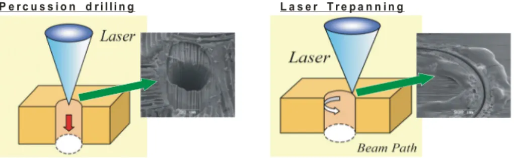
Figure 4 - Conventional laser drilling techniques applied in case of CFRP and related drawbacks.
ED=0.06J/mm2 ED=0.3J/mm2 ED=0.65J/mm2
ED=0.06J/mm2 ED=0.3J/mm2 ED=0.65J/mm2
113 The technique of percussion drilling aimed at obtaining small diameter hole through a train of pulses with low repetition rate (typically 50-100Hz) produces a relevant thermal damage of the matrix, as shown in figure 4. The overexposure of the impact point to high ED can readily remove carbon but is quickly conducted thus inducing degradation of the polymer especially along the fibers.
Similarly the trepanning technique produces a circular track of limited depth. This is due to the fact that the edges of the circular cut are characterized by swelled fibers whose irregular profiles are able to trap the beam by multiple reflections preventing the progression of the cut. Even in this case the localization of the energy density on the boundary line of the hole causes thermal degradation of the matrix as reported in figure 4.
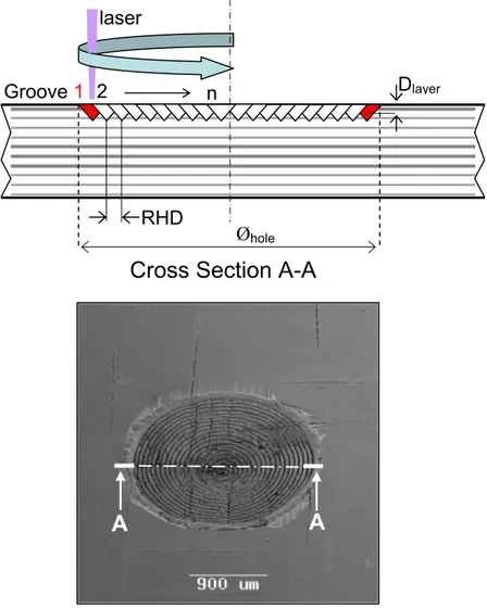
Figure 5 – SEM picture of circular concentric grooves (RHD=100µm) on a CF-PEEK laminate and strategy for the removal of a layer in cross-section A-A. In order to reduce the afore mentioned drawbacks which are mainly due to the non-homogeneous nature of CFRP, a different removal technique based on the
Groove
1
2
n
RHD
D
layerØ
holelaser
A
A
ablation of multiple layers of material was proposed. Figure 5 represents the draft of a hole cross section and outlines the concept of superimposing the groove profiles represented with triangular shape. The removal of a layer should be obtained through the ablation of concentric circular grooves whose diameter decreases from the hole nominal diameter according to a fixed step called radial hatch distance (RHD) which represents the main process parameter in addition to the ED adopted.
The selection of the correct hatch distance should theoretically provide a partial overlap of circular grooves thus generating the removal of one layer. This value depends on the width of the groove that the beam leaves on the material.
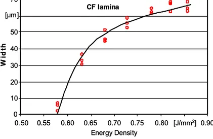
In [8] is reported that in case of polymers processing with IR laser, groove width tends to assume a limit value corresponding to the spot diameter at the increasing of the energy density. This is due to the very small thermal conductivity and diffusivity of these materials.
Measurements of the grooves previously analyzed to determine the ED threshold values, show that in case of CF the action of the 355nm beam allowed widths much broader than the adopted spot diameter (25µm), as reported in figure 6. This is due to the high conductivity of the fibers.
Figure 6 - Groove width on a CF lamina versus energy density
Following the afore mentioned considerations first drilling tests were carried out with the a 355nm DPSS laser a pulse repetition rate of 90kHz. The laser beam was guided by mirrors into a galvometer driven scanner unit, which allows a highly dynamic beam deflection of over 2m/s. A first analysis concerned the ablation of circular layers on a 2.5mm thick PEEK-CF laminate realized with the following stacking sequence: (0°,90°,+45°)Sym .
Since the joining of composite laminates by means of rivets commonly requires small diameter drillings, first tests were conducted on the ablation of circular layers with a diameter of 2mm. Due to the small dimension of the hole and to the extremely high scanning speeds, it was decided to ablate the whole area in order to define the better parameters for the removal of the first layer and demonstrate
0 0.50 0.55 0.60 0.65 0.70 0.75 0.80 0.90 CF lamina 0.55 Energy Density [µm] Wi d th 10 20 30 40 50 70 [J/mm2] 0 0.50 0.55 0.60 0.65 0.70 0.75 0.80 0.90 CF lamina 0.55 Energy Density [µm] Wi d th 10 20 30 40 50 70 [J/mm2]
115 the repeatability of the removal of multiple layers varying ED in the range of 0.6-0.9 J/mm2 and the radial hatch distance in the range of 10-200µm.
Figure 7 – SEM picture of circular concentric grooves (HD=150µm) on a CF-epoxy laminate and real profile of a layer.
The first aspect noticed was a not uniform depth of a layer (Dlayer) in radial direction: internal grooves offered a deeper penetration than those with higher diameters as described in figure 7. This phenomenon can be directly related to the secondary heat release generated by UV ablation, especially at high ED: when diameters become smaller the energy input is localized in a reduced area and in addition the time between each groove is not enough to provide a sufficient cooling. The secondary heat transfer delivered after the ablation of a generic groove (n) then acts as a pre-heating effect on the material allowing deeper penetration for the successive groove (n+1).
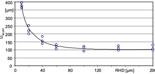
Figure 8 - Non-linear decrease of the ablation depth in relation to the radial hatch distance. Process parameters: Paverage=20W, Vscan=1m/s, Øspot=25µm, f=90kHz. The above mentioned phenomena leading to disuniformities in the depth of a layer increase with a reduction of the hatch distance. Figure 8 shows that the dependence of Dlayer (measured as the distance of the maximum penetration from the entry side surface) on RHD is non linear and related to thermal effects for values lower than 50µm which generate an almost complete superposition of the
Cross Section A-A
1
n
Ø
holeLayer
A
A
D
layer 0 50 100 250 300 400 0 40 80 120 RHD [µm] 200 [µm] Dla y e r 150 200 0 50 100 250 300 400 0 40 80 120 RHD [µm] 200 [µm] Dla y e r 150 200groove profiles. Radial hatch distances higher than 50µm generate a quite constant depth of about 100µm. A second aspect noticed from figure 8 is that to obtain a flat ablation surface in composite material overlapping of effective laser beam traces is not necessary. This phenomenon also noticed by [16] can be explained considering that in the case of laser machining of fibre reinforced composite, material removal can be either by laser direct ablation or through ejection of small pieces of chopped carbon fibres. Fibers are chopped into small pieces if the spacing of laser beam traces is greater than effective beam size.
The heat accumulated within the small pieces of fibres is retained due to the fact that no further heat conduction is taking place through the fibre. The temperature within the small pieces of fibres further increases. It may not lead to direct carbon fibre vaporisation, but it is sufficient to heat up the surrounding polymers. The heated polymer may vaporise or loss the capability of holding the fibres in position. In other words, fewer circular grooves are needed to obtain the removal of a layer in CFRP laminates than in a conventional bulk material with similar vaporisation/melting temperature.
The wider spacing reduces the number of grooves required to obtain a given depth of a layer and the time of drilling through a material is therefore reduced.
By means of the ablation of multiple superimposed layers, with hatch distance ranging between 100µm and 200µm, it was possible to drill through the thickness of the material with a significant reduction of the energy density acting on the material. Differently from percussion drilling and trepanning, during the removal of layers, the beam acts on the whole surface to be removed thus reducing energy density input and consequently thermal damage. In this way degradation of the polymer matrix was prevented either on the external layer or on the internal surface of the hole where it could generate serious interlaminar fracture and fibers swelling.
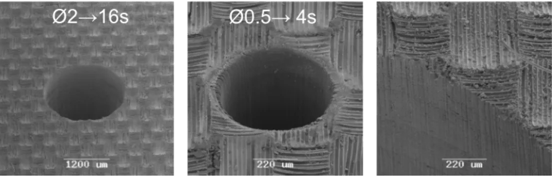
Figure 9 – Process parameters: unidirectional laminate with (0;90;+45)s stacking sequence, matrix PEEK, thickness 2.5mm, wavelength 355nm, frequency 90kHz, pulse duration 15ns, Paverage 23W, Vscan 1m/s, RHD 100µm, Øspot 25µm.
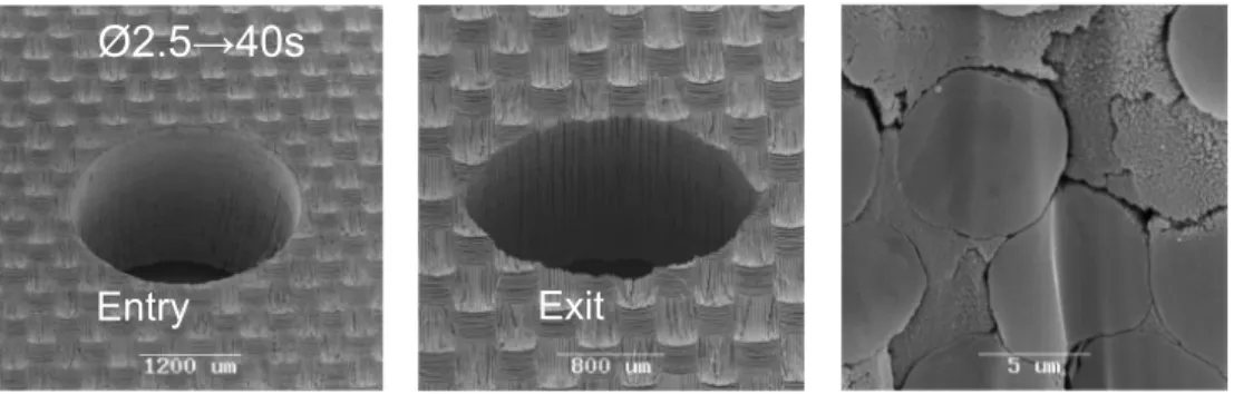
Results in figure 9 show that the proposed technique allows through drilling of the CFRP laminate (2mm diameters in 16s) without thermal damage. Holes with 0.5mm diameter can be also obtained through the removal of successive layers without a relevant HAZ on the edges. The internal surface of the hole is continuous and not affected by delamination deriving to the melting of the polymer matrix which still fills the gaps between fibers. The risk of internal failure due to
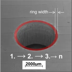
117 delamination after UV-laser drilling can be then reduced comparing to conventional machining process or even to the application of traditional high power IR lasers. When holes with diameter bigger than 2mm have to be obtained, the removal of multiple layers, even using high radial hatch distances, generates long process times which may restrict the industrial significance of the proposed technique. In this case, it is possible to remove only an external ring of material for the whole thickness of the laminate, as illustrated in figure 10. The width of the ablated ring must be large enough to guarantee the complete penetration of the beam inside the track thus avoiding entrapment due to multiple reflections. The ejection of chopped fibers by the bottom surface is also guaranteed at large widths: in this way it is possible to remove from the track the main cause of internal HAZ.
Figure 10 – Process parameters: unidirectional laminate with (0;90;+45)s stacking sequence, matrix PEEK, thickness 2.5mm, Øhole 5mm, wavelength 355nm, frequency 90kHz, pulse duration 15ns, Paverage 23W, Vscan 1m/s, RHD 100µm, Øspot 25µm, ring width 0.5mm.
The ring width is also influenced by the laminate thickness since the laser beam remains focused in a nearly 25µm spot diameter only in the Rayleigh range (around 0.5mm for the laser adopted). Out of this range ED decreases varying the ablating conditions.
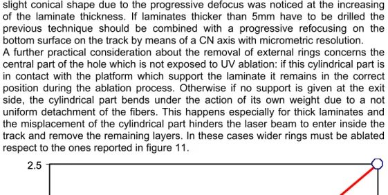
Tests were carried out drilling holes whose diameters varied in the range of 5mm to 20mm in laminates of thickness varying in the range [0.5-2.5-5-7.5]mm keeping the focal plane on the top surface of the material. Results shown in figure 11 reveal that a threshold boundary line determines the minimum values of the ring width to be adopted depending on the drilled thickness. Once established a uniform removal rate per layer by means of UV-ablation this results are not depending on radial hatch distance and hole diameter. As shown in figure 11 it was possible to drill CF-PEEK laminates up to 7.5mm thickness using a single focal position on the surface with a good quality of the circular edges (entry and exit side). Cross sections of the drilled holes revealed almost perpendicular internal surfaces: a
1.
→
2.
→
3.→ n
ring width
slight conical shape due to the progressive defocus was noticed at the increasing of the laminate thickness. If laminates thicker than 5mm have to be drilled the previous technique should be combined with a progressive refocusing on the bottom surface on the track by means of a CN axis with micrometric resolution. A further practical consideration about the removal of external rings concerns the central part of the hole which is not exposed to UV ablation: if this cylindrical part is in contact with the platform which support the laminate it remains in the correct position during the ablation process. Otherwise if no support is given at the exit side, the cylindrical part bends under the action of its own weight due to a not uniform detachment of the fibers. This happens especially for thick laminates and the misplacement of the cylindrical part hinders the laser beam to enter inside the track and remove the remaining layers. In these cases wider rings must be ablated respect to the ones reported in figure 11.
Figure 11 – Ring width versus laminate thickness. Process parameters: laminate unidirectional with (0;90;+45)s stacking sequence, matrix PEEK, wavelength 355nm, frequency 90kHz, pulse duration 15ns, Paverage 23W, Vscan 1m/s, Øspot 25µm.
Further tests were performed with DPSS lasers in the second (532nm) and basic harmonic (1064) in order to determine if a proper ablative process could be established also at wavelengths higher tan the UV range.
At this purpose, arrays of 2mm diameter holes have been practiced in the same CF-PEK laminates with a green laser source (532nm) with a pulse duration of 5-10ns. Figure 12 shows that it was possible to obtain a proper ablation process using ED comparable to those previously adopted: this is demonstrated by the presence of non-melted polymer between the fibers. A conical shape of the holes, higher than in case of UV ablation, was noticed: this phenomenon is due to the lower energy per pulse provided by photons at this wavelength and can be partially optimized by increasing the pulse repletion rate.
0 0.5 1.0 1.5 [mm] 2.5 1 2 3 4 5 [mm] 7
Laminate thickness
Rin
g
wi
d
th
DRILLING THROUGH
ZONE
BEAM ENTRAPMENT
0 0.5 1.0 1.5 [mm] 2.5 1 2 3 4 5 [mm] 7Laminate thickness
Rin
g
wi
d
th
DRILLING THROUGH
ZONE
BEAM ENTRAPMENT
119 Figure 13 shows that it is also possible to maintain an ablative process with a wavelength of 1064nm. The use of IR emission forces to adopt shorter pulse duration than the previous two sources analyzed in order to prevent a drastic thermal transfer and a wide HAZ. The use of pulses in the order of ps reduces this phenomenon but, however, a significant melting of the PEEK matrix can be noticed at the entry side as well as in the internal cylindrical surface.
Figure 12 - Process parameters: unidirectional laminate with (0;90;+45)s stacking sequence, matrix PEEK, thickness 2.5mm, wavelength 532nm, frequency 90kHz, pulse duration 5-10ns, Paverage 8W, Vscan 1m/s, RHD 100µm, Øspot 35µm.
Figure 13 - Process parameters: unidirectional laminate with (0;90;+45)s stacking sequence, matrix PEEK, thickness 2.5mm, wavelength 1064nm, frequency 200kHz, pulse duration 8-10ps, Paverage 2W, Vscan 1m/s, RHD 100µm, Øspot 40µm.
8.6 LAMINATE REPAIR
On site scarf repair is up to now the best alternative for aeronautic parts in which one side of the assembled structure is not reachable. The material removal needs expert manpower and as main drawback cannot be readily generalized for different repair applications. It is, then, advantageous to develop a faster removal technique to be employed in a wide range of applications, allowing a high accuracy in the machining of the cavity.
At this purpose, a promising technique is represented by Laser Beam Machining (LBM) since the contactless removal generated by the laser light on the laminate completely avoids two critical drawbacks which are typical in the use of
Entry
Ø2.5→40s
Exit
Entry
Ø2.5→3min
Exit
conventional grinding tools: the rapid tool wear due to the abrasive action of the carbon fibers and the mechanical stresses generated on the workpiece which may cause delamination.
The repair process of cracks and dry spots in CF-laminates is up to now, a difficult and time consuming task. Depending on the geometry of the CFRP part, the grinding process of a mechanical material removal may take several work-days. Usually, mechanical repair strategies involve a selective grind of single fibre layers by diamond angle grinders. The picture in figure 14 illustrates the concept generally used repair for CFRP.
Hole Filler ply
Ply of film adhesive Ply of film adhesive
Repair plies Additional repair ply
Figure 14 - Repair concept for CFRP.
The generated staircase-shaped structure as shown in figure 14 is manufactured in different ratios of depth to width of each step. Afterwards the repair structure has to be filled up with appropriate pre-preg plies and the whole system must finally be cured with vacuum bag technique. The quality and the resolution of the grinding process strongly depend on the expertise of the trained personnel and are limited by the restriction of the grinding tool. This implies a large potential for “human error”, which is crucial for high level safety industries, like the aerospace sector.
Figure 15 - Ablation principle: ablation by multiple scanned hatch cycles in alternated hatch directions.
121 To asses the efficiency of the laser technique proposed in this paper, experiments of layer removal on CF-PEEK were performed using the over mentioned 355nm laser. The ablation of a layer is realised by hatching the area with parallel laser lines as shown in figure 15. In order to flatten the ablated surface, the hatching direction was alternated 0°-90° for every couple of layers thus neglecting the influence of fibres direction on the depth of the cavity. Once determined the depth per cycle (couple of crossed layers), the total depth of the cavity was then controlled only by the cycles number. According to (2), the depth per cycle ranging from 1µm to 25µm can be controlled by varying the laser parameters. The depth
per cycle normally increases with a reduction of hatch distance (figure 16).
Figure 16 - Non-linear decrease of the ablation depth in relation to the hatch distance.
This dependence is non-linear and related to thermal effects which are not negligible in case of hatch distances lower than 30µm. The described laser machining setup allows a high precise ply-by-ply material removal of CFRP laminates without any thermal damage or delamination as illustrated by the micro computed tomography (µCT) picture in Figure 17.
It was then possible to obtain an HAZ-free material removal using the photochemical bond-breaking provided by 355nm wavelength. In addition it was possible to obtain a high resolution of the cavity depth by means of the low penetration of UV-laser radiation, as also reported in [17]. A step cavity geometry with a ratio 1:20 is displayed in figure 18 which illustrates the precise layer by layer removal.
Furthermore this laser machining setup is eligible to prepare the filling repair plies with the same precision as the ablation for the repair structures [18]. The cutting speed for plies with a thickness of 140µm is up to 0.4m/s. In both cases, the repair geometry and the preparing of the repair plies, the shape of the machined geometry can be easily adopted by simply modifying a CAD template.
0
20
40
60
80
100
0
1
2
3
4
5
Ablation
depth
[m
m
]
Hatch distance [µm]
Hatch cycles 15
Beam deflection 400mm/s
Spot diameter 25µm
0
20
40
60
80
100
0
1
2
3
4
5
Ablation
depth
[m
m
]
Hatch distance [µm]
Hatch cycles 15
Beam deflection 400mm/s
Spot diameter 25µm
In addition to the full material ablation and the cutting of pre-preg plies, the two different ablation thresholds mentioned above and shown in figure 2, allow a
selective excavation of the fibres from the adherent matrix material by means of a precise control of process parameters.
Figure 17 - µCT-picture of a step cavity geometry (ratio 1:20) performed with: wavelength 355nm; repetition rate 90kHz; pulse duration 15ns.
This laser cleaning of fibres provides an adhesive strength improvement of the filling repair plies and as a consequence the result of the laser based repair process is supposed to be more stable than the conventional one.
a)
b)
Figure 18: a) Laser process (parameters reported in figure 6); b) Step cavity with a 1:20 ratio and a precise layer by layer removal.
As a final step of the research, the laser-based repair was compared to the conventional process for a standard repair geometry in a 4mm thick CF-PEEK laminate. The dimensions of the step cavity were: depth per step 140µm with a ratio of 1:20, total depth of 1.96mm, squared shape with a width of 84.8mm. Results show that process time required for the conventional mechanical process was around 40h whereas for the laser based repair the process time was reduced to less than 12h. Additionally the laser based repair process provides:
- high resolution of the material removal (1µm for cavity depth); - improvement of the adhesive strength;
- standardization and automation of the process;
beam speed 0.4m/s Hatch distance 75µm Hatch cycles 15
123 - flexibility in changing the cavity design.
8.7 CONCLUSION
It has been proved that DPSS laser emitting in the UV region represent a promising alternative for processing of “difficult-to-machine” materials, like CFRP especially in the field of precise machining represented by the laminates drilling and repair process. Experimental results demonstrate that even if very different thermo-physical properties characterize carbon fibers and polymer matrix, the use of layer by layer UV-ablation enables a detailed machining without inducing thermal damage on the composite materials, once established the proper process parameters in terms of energy density and hatch distance. Moreover the innovative processes proposed for drilling and repair seem to be fast enough to guarantee a successful economic implementation.
In summary, when laser drills thick composite laminates, the material removal efficiency can be optimised by removing complete layers of material or even a ring shape instead of cut single track in order to reduce the shielding of incident beam by plasma and plume. In this way heat affection to the workpiece is prevented and HAZ is eliminated. It was also shown how the high thermal conductivity of the fibers allows higher radial hatch distances than those obtainable by a partial superposition of single circular grooves.
As far as the repair is concerned, the strength of the repaired patch and the performance obtainable by the laser-based repair process has to be investigated accordingly to the standard test method ASTM D1002.
The increase of scarf angle which characterize the step cavity, provides a further possibility of process optimisation. The ratio conventionally used in the manual process is limited to 1:20, due to the geometries of the grinding tools. This problem was solved with scanning technology whose 5µm-resolution allows ratios of 1:10 or 1:5. This decreases the cavity dimensions and consequently the process time. The effective strength of laminates repaired with these ratios represents a further objective for a future research as well as the certification and standardization of the proposed technique for the aerospace sector.
8.8 REFERENCES
[1] J. Moutier J., Fois M., Picard C., 2009, Characterization of carbon/epoxy materials for structural repair, of carbon/BMI structures, Composites: Part B 40, pp.1–6.
[2] Tagliaferri V., Di Ilio A., Crivelli Visconti I., 1985, Laser cutting of fibre reinforced polyesters, Composites, v 16 n 4, pp.317-325.
[3] A.A. Cenna, and P. Mathew, 1997, Evaluation of cut quality of fibre-reinforced plastics – a review, Int. J. Mach.Tool Manufact., vol. 37(6), pp. 723-735. [4] G. Caprino, V. Tagliaferri, 1988, Maximum cutting speed in laser cutting of
fibre reinforced plastics, Int. J.Mach. Tool Manufact. , vol. 28, pp. 389-398. [5] G. Caprino, V. Tagliaferri and L. Govelli, 1995, Cutting GFRP using CO2 laser
with multimodal Gaussian distribution, Int. J. Mach. Tool Manufact., vol. 35(6), pp.831-840.
[6] E. Uhlmann, G. Spur, H. Hocheng, S. Leibelt, C.T.Pan, 1999, The extent of laser-induced thermal damage of UD and cross ply composite laminates, Int. J. Mach.Tool Manufact., vol. 39, pp. 639-650.
[7] Herzog D., Jaeschke P., Meier O., Haferkamp H., 2008, Investigations on the thermal effect caused by laser cutting with respect to static strength of CFRP, International Journal of Machine Tools & Manufacture 48, pp.1464- 1473. [8] K.T. Voisey, S. Fouquet, D. Roy, T.W. Clyne, 2006, Fibre swelling during
laser drilling of carbon fibre composites, Optics and Lasers in Engineering 44 pp 1185–1197
[9] F.C. Campbell, Manufacturing processes for advanced composites, Elsevier, UK, pp. 442.
[10] Tönshoff H.K., Hesse D., Mommsen J., 1993, Micromachining using excimer lasers, CIRP Annals – Manufacturing Technology, Vol.42/1, pp.247-251. [11] B. Denkena, F. Volkermeyer, R Kling and Hermsdorf, 2007, Novel UV-laser
applications for carbon fibre reinforced plastics”, J. Appl. Prod. Technol., APT’07,Bremen, Germany, pp. 99-105.
[12] Völkermeyer F., Kling R., Denkena B., 2007, Flexible and damage minimized machining of fiber plies and CFRP by UV-Laser radiation, Proceedings of CFK-Valley Stade Convention, Germany, pp. 135-137.
[13] Sato H., Nishio S., 2001, Polymer laser photochemistry, ablation, recostruction, and polymerization, Journal of Photochemistry and Photobiology C: Photochemistry Reviews 2, pp.139-152.
[14] J. Flöck, K. Friedrich, Q. Yuan, 1999, On the friction and wear behaviour of PAN- and pitch-carbon fiber reinforced PEEK composites, Wear, pp.304-311. [15] Romoli L.; Tantussi, G.; Dini G., 2007, Layered Laser Vaporization of PMMA
Manufacturing 3D Mould Cavities, CIRP Annals – Manufacturing Technology, Vol. 56/1, pp. 209-212.
[16] Z.L. Li, P.L. Chu, H.Y. Zheng, G.C. Lim, L. Li, S. Marimuthu, R. Negarestani, M. Sheikh, and P. Mativenga, 2008, Process development of laser machining of carbon fibre reinfoenced plastic composites, 27th International Congress Application of Lasers and Electro-Optics (ICALEO08), Temecular, CA, USA, 20-23October 2008, pp. 222-230.
[17] Srinivasan R., Leigh W., 1982, Ablative Photocomposition Action of Far-UV Laser Radiation of Polyethylene Films, J.Am.Chem.Soc. (104), pp. 6784-6785.
[18] Völkermeyer F., Fischer F., Kling R., 2009, Advanced capabilities in machining of CFRP by innovative laser-based techniques, Proceedings of CFK-Valley Stade Convention, Germany, pp. 34-39.