9
1 Near-field focused arrays
for fixed RFID readers
In a typical RFID portal for supply-chain or warehouse management, the distance between the reader and the tags is usually less than 1-2 m, and it can happen that adjacent portals are very close to each other. In such situations, it becomes important to limit the interference between nearby portals (which often requires expensive and large metallic or absorbing shields) and reduce reading errors due to multipath phenomena. Both above problems can be mitigated by resorting to an array antenna, whose radiation pattern can be shaped by properly feeding its array elements. However, for relatively large UHF arrays, tags located at 1-2 m from the antenna aperture result to lie in the near-field region of the array, and not in its far-field region as is usually the case in standard communication systems. Therefore, the best choice for the reader antenna consists of an array exhibiting a NF focused radiation, namely an antenna which is able to maximize the field amplitude in a size-limited spot within the antenna near-field region, while reducing the field strength far from the antenna (far-field region). A planar NF focused antenna can be realized by a conventional microstrip array with a proper microstrip feeding network, without any electronic control system as, for instance, that required by scanned-beam antennas. It means that a conventional reader antenna can be interchanged with a 50 input impedance NF focused antenna by a simple antenna-connection procedure, for any existing commercial reader.
The main idea is to control the phase of the radiation sources on the antenna aperture (array element currents or equivalent surface currents) in such a way that all their contributions sum in phase at a focal point located close to the same aperture. In conventional far-field focused antennas, a uniform phase distribution on the antenna aperture is adopted to focalize the radiated field at infinity (far-field region). Alternatively, a linear phase shift is implemented in phased arrays to scan the beam from the broadside direction. In NF focused antennas a maximum of the radiated field is
10
obtained at a point in the antenna NF region (actually at a distance smaller than the focal distance) by implementing a symmetric phase tapering able to compensate for the different distances between each source point on the aperture and the focal point (it can be approximated with a quadratic phase distribution for focal distances that are large with respect to the antenna aperture size). For a given amplitude of the radiated field at a point in the far-field region, the above maximum will be greater than that obtained from the corresponding far-field focused array (which is named as Equal-Phase Array, EPA, in the following). This means than in an RFID portal the field incident on the tags can be increased while still meeting the specifications on the maximum allowed EIRP (Effective Isotropic Radiated Power).
In this chapter, after a brief overview of antennas for RFID readers, the properties of NF focused antennas will be summarized with different application examples. The design and characterization of a planar NF focused antenna for fixed reader operating in the 2.4 GHz ISM band (2.4-2.48 GHz) will be shown and compared with those of the corresponding far-field focused array, with a focus on both axial and transverse power distributions [5]-[6].
1.1
RFID reader antennas
Antennas for RFID readers in the HF band (13.56 MHz) are mainly constituted by loop antennas. In the UHF band (840-965 MHz) or microwave band (2.4-2.48 GHz), reader antennas are often realized by a circularly polarized patch, providing low-cost and low-thickness radiators. Recently, fixed-reader antennas are becoming more complex patch arrays which are required to obtain high gains, narrow beams and low sidelobe levels. Both fixed-beam arrays [27]-[28] and phased arrays [29]-[30], namely pattern reconfigurable antennas, have been presented in the literature.
A dual-linear polarization 2x2 array consisting of 5cmx5cm patches has been presented in [27], where a slot-coupling feeding technique has been used to cover a 5% bandwidth around 2.4 GHz. The array exhibits a 14 dBi gain with 36° beamwidth in both E and H principal planes. A low-sidelobe series-fed linear array made of 6 circularly polarized patches (corner-fed nearly-square patches resonating at 2.4 GHz) has been designed in [28], where a -23 dB sidelobe level has been obtained through a Chebyshev tapering excitation. The array size is 50cmx10cm, and the antenna exhibits a 16° beamwidth with a gain of 11.2 dBi. In [29], a 3x2 phased array operating at the lower UHF RFID frequency band (868-965 MHz) has been presented. The array is 50cmx50cm large, and exhibits a 10.7 dB broadside gain, a 42° beamwidth at broadside and up to 40° elevation beam scanning. A five-patch smart linear array at 2.4 GHz has been studied in [30], where the antenna beam can be rotated through digitally controlled 4-bit phase shifters. In particular, the effect of the phase quantization error on a Dolph-Chebyshev radiation pattern has been studied.
11
While all previous works considered radiated field properties only in the far-field region, in [31], the design of a reader antenna for an over-the-conveyor RFID tunnel system also accounted for its near-field radiation characteristics. In particular, a linear array of 3 circularly polarized patches (to be located under the conveyor belt) was properly fed to shape the field strength to let an RFID reader detect only the box located just above the antenna.
In spite of their advantages in reducing multipath effects, the cost and complexity of phased arrays are delaying their widespread application. In [29], the authors recognized that smart antennas for RFID readers have not yet emerged as the mainstream enabling technology. For the above reasons, a NF focused array with a fixed pattern, which does not require any additional control electronics, could represent a trade-off alternative.
1.2
Near-field focused antennas
Although NF focused antennas have been studied over a long time, their applications are limited in number [5]-[8], [32]-[41], when compared to antennas for communication systems and radars, which are focused in the far-field region. A NF focused array can be used to maximize the electric field amplitude in a limited-size spot around a given focal point located nearby the antenna aperture (in the antenna near-field region). NF focused antennas have been applied in several areas such as gate access control systems [7]-[8], local hyperthermia and imaging in biomedical systems, as well as in remote (Non-contacting) subsurface inspections [32]-[33], and temperature monitoring [34] in microwave industrial applications. They have also been considered in wireless microwave power transmission systems, as for example solar power satellites [40] and systems for powering small aircrafts [41].
In microwave focused antennas, a proper phase tapering of the aperture equivalent currents (or feeding currents of the array elements) is used to get an in-phase summation of the aperture contributions at a given focal point. NF focused antennas can be realized by pyramidal or conical horns with a focalizing lens in front of the antenna aperture, but usually they are heavy, bulky and expensive. Alternative solutions are based on either reflector antennas or Fresnel Zone antennas [42]-[43], but they are still non-planar antennas. On the other hand, lightweight, low-profile, as well as low-cost NF focused antennas can be obtained by using planar microstrip arrays with a feeding network exhibiting relatively small differences with respect to a corporate feeding network of a conventional broadside array. The above small differences in the microstrip feeding network are needed to obtain a set of different relative propagation delays between the array elements, and they do not require any additional construction cost.
In [7]-[8], NF focused arrays operating at lower frequencies have been designed for gate access control systems in the GSM1800 frequency band (1710-1880 MHz). The idea is to confine the electromagnetic field in a spot region involving just one user and limit the interference with other nearby mobile users. As already said, microstrip
12
technology allows to realize a low-profile antenna, which is suitable for installation at the room ceiling. In the arrays, an aperture coupled feeding technique has been used to achieve a percentage bandwidth up to 9.4%.
In [32]-[33], a NF focalized microstrip array of U-shaped patches has been realized to be used as a sensor for non-contact, non-destructive microwave inspection of small dielectric objects in the frequency band 10-12 GHz. It has been shown that the system using the compact focalized microstrip array exhibits the same sensitivity as that of free-space sensors using a cumbersome X-band horn antenna loaded with a dielectric lens. Moreover, a microwave radiometer working at 12.5 GHz is described in [34] for food industry. In such applications where health and safety regulations often require documentation that cooked meat products have reached a certain minimum interior temperature, the microwave radiometer has the advantage to not absorb or scatter significantly by airborne particulate and to be able to provide both interior and surface temperatures just choosing a proper radiation wavelength. The proposed antenna is a NF focused array of 8x8 inset-fed patches.
As an alternative to square NF focused arrays, a circular NF focused array can be used [35]. A square aperture provides smaller focal spot and side lobe level with respect to a circular one, but the latter can implement the focalization effect with a simpler feeding network. A tunable NF focused circular array is proposed in [35] for 5.8 GHz RFID applications.
Antenna synthesis techniques can be adopted for NF focused arrays as usually done for far-field focused arrays. Since the NF focused arrays show in the focal plane the same properties of the conventional equal-phase arrays in the far-field region [42], an amplitude tapering can be implemented in addition to the phase tapering. For example, in [7] and [34] a 20 dB Taylor amplitude tapering is used, while [36] adopted the Dolph-Chebyshev technique to satisfy severe constraints on side lobe level performance. In [37] the steepest decent method is used to synthesize the phases of a 16x16 microstrip array which operates at 24 GHz and can be used for the remote vital-sign detection. Furthermore NF focused arrays with a non-uniform element distribution have been proposed in [38] for a fractal array. An extension of the near-field focusing technique to reflectarrays has also been presented in [39].
As already hypothesized in [36], NF focused antennas could find application in wireless microwave power transmission [40]. In these systems the basic idea is to collect the solar power at the satellites and transfer it from space to earth or from space to space. Although the involved distance are relatively huge, it can happen that (for an assigned set of values of the operating frequency, the distance between the transmitter and the receiver, and the transmitter antenna size) the receiver antenna could be located in the near-field region of the transmitter antenna. It follows that a NF focused transmitter antenna could be used to improve power transfer efficiency for a given maximum allowed interference level far from the receiver. Large earth-based arrays for wireless microwave powering of cooperative targets (e.g. unmanned aircrafts) [41] can be a further situation where the target is in the near-field region of the transmitting
13
antenna; in this case, the adaptive phase tapering can be used not just to steer the main beam toward the target but helpfully to focalize the radiated field at the target instantaneous position.
In some classical papers on NF focused antennas [42]-[47], it has been shown that NF focused antennas are characterized by a far-field like pattern in both the focal region (transverse plane at the focal point) and the far-field region. In the focal plane, the properties of a focused aperture antenna remain the same as those of the corresponding uniform phase aperture [42], as the focal point moves from infinity towards the antenna aperture, when the focal point remains at a distance greater than the antenna aperture. For a given focal distance (between 1 m and 2 m, in RFID portals), a relatively high power density at the focal spot can be obtained with large antennas at short wavelengths. This means that better results can be obtained at 2.4 GHz, instead of at the lower UHF RFID band (868-965 MHz), for a given size of a square array (while even better improvements can be obtained for future RFID systems at 5-6 GHz).
In contrast to conventional antennas focused at infinity, NF focused antennas are characterized by an axial pattern around the focal point, in addition to the standard transverse plane patterns. Characteristic parameters of axial patterns are the Depth of Focus (DoF) (distance along the axis between two points where power density is 3 dB below its maximum value) and the relative amplitude of forelobes and aftlobes, more details will be in Chapter 2. Also, due to the field spreading factor 1/r, the peak of the axial field amplitude does not occur exactly at the focal point (where all field contributions sum in phase due to the proper aperture phase tapering), but it does arise at a point between the antenna aperture and the focal point. The above focal shift has been studied in [46], where design curves of focused apertures have also been derived as a function of the normalized antenna aperture and the focal distance.
While phase tapering is essential to focus the radiated field at the focal point, an amplitude tapering (direct or inverse) can be used to control the sidelobe level in both the axial (axial forelobes and aftlobes) and the transverse directions. As far as focal plane transverse patterns are concerned, array synthesis techniques used for conventional far-field focused arrays (EPA) can be applied to shape the far-field like patterns of NF focused arrays. Moreover, Graham [45] suggested a technique to synthesize a given axial pattern around the focal point, starting from the expressions of classical amplitude taperings used for transverse plane pattern synthesis. However, Hansen [46] has shown that direct taperings for sidelobe reduction in the focal transverse plane originate aftlobes and forelobes which are higher than those corresponding to uniform excitation; on the other hand, inverse distributions provide lower aftlobes and forelobes, but higher sidelobes and lower efficiency. Therefore, the uniform excitation becomes the best choice to achieve similar sidelobe levels in both transverse and axial directions, without reducing the near-field antenna gain . Since in RFID portal systems the main goal is to increase the field amplitude at the near-field spot, a uniform amplitude excitation has been chosen for the array designed.
14
1.3
Design of a near-field focused array for RFID readers at 2.4
GHz
A NF focused planar array of 8x8 circularly polarized patches resonating at 2.4 GHz has been designed [5]-[6]. The aim of the research activity was the design of an array able to maximize the field in a size-limited spot (20-30 cm diameter) close to the antenna aperture (at a distance of around 1.5 m), while exhibiting a rapid field amplitude spatial decay outside the above region, to reduce interferences with tags passing through adjacent RFID portals. The latter requirement is also needed to reduce interference with other devices located in the same environment and working at nearby frequencies (as for example wireless local area networks). The spot size of a NF focused planar array depends on the inter-element distance, array size and geometry, required focal length and phase profile at the antenna aperture. On the basis of both theoretical analysis [46] and numerical trials, proper values for the above parameters have been designed. Both the single element and the array have been designed and optimized by using Ansoft Designer™. The antenna radiates a left-hand circularly polarized field (LHCP radiation) to reduce the dependence of the RFID system performance on random tag orientations.
1.3.1 Single element design
The array element is a nearly square patch, with a side of about 29 mm (Fig. 1.1). It is printed on a 1.6 mm FR4 substrate (εr=4.4 and tanδ=0.02) and fed by a 50 microstrip line. To obtain a circular polarization, two orthogonal modes with a 90° time-phase difference must be excited. To avoid a bulky double-feeding technique, a single-port feed has been implemented, which requires the ends of two opposite corners of the patch to be trimmed.
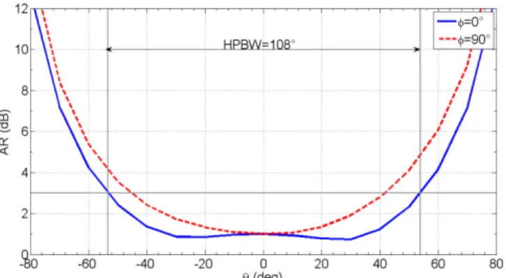
The patch radiation pattern in the principal planes is shown in Fig. 1.2. The patch exhibits a half-power beamwidth (HPBW) of about 108° in both principal planes. It is worth noting that radiation patterns in Fig. 1.2 are calculated in the patch far-field region. Fig. 1.3 shows the reflection coefficient at the antenna feeding port, while Fig. 1.4 represents the Axial Ratio (AR) at 2.4 GHz in the principal planes at and (versus the observation angle measured from the broadside direction).
15
Fig. 1.1 - The basic element of the 8x8 NF focused array: a single-port circularly polarized patch (LHCP
polarization).
Fig. 1.2 - Co-polar (LHCP) and cross-polar (RHCP) components of the single element radiation pattern in
both principal planes (=0° and =90°), at 2.4 GHz.
16
Fig. 1.4 - Axial Ratio of the LHCP patch in the broadside direction for both principal planes (=0° and =90°), at 2.4 GHz.
1.3.2 8x8 array
The final antenna is an 8x8 patch array. The phase of the patch feeding currents has been adjusted to maximize the radiated field at a distance r0=1.5 m (r0=12λ where λ is
the free-space wavelength at 2.4 GHz) from the antenna aperture, along the axial direction orthogonal to the antenna aperture. According to the formula D=(r0/L)x0.886
[42], where D is the diameter of the -3 dB circular spot area, an LxL=80cmx80cm (6.4λx6.4λ) aperture is necessary to obtain a 20 cm spot area. Thus, it follows that for an 8x8 array a distance between patches equal to 0.8λ has to be chosen. The array layout is shown in Fig. 1.5.
Since the focal point is located in the Fresnel region [46] of the array (r0=12λ<R=2L2/λ=82λ), the focusing process is effective in maximizing the field
amplitude in a spot around the focal point. The general procedure to focalize the beam at a certain distance from the aperture rather than in the far-field region is based on applying a proper phase shift at each patch current to compensate for the distance of the same patch from the focal point (Fig. 1.6). Let us suppose that the antenna aperture is in the xy plane and (xi,yi) are the single element coordinates (Fig. 1.6); the above phase
shifts can be calculated as in (1.1):
2 2 2
0 0 2 i xi yi r r (1.1)In particular, Tab. 1.1 shows the phase shifts for all the elements of the second-quadrant 4x4 subarray, when calculated with respect to the upper-left patch. The phase shifts for the other subarrays can be easily evaluated by considering the array symmetry. The phase shift profile has been implemented by properly varying the relative length of the feeding lines reaching each patch. The length differences depend on the microstrip guided wavelength (λg=67.56 mm at 2.4 GHz for the 50 microstrip line) and they are illustrated in Tab. 1.1. To account for the shift of the field peak towards the array
17
aperture [46], phase shift in Tab. 1.1 have been calculated by using r0=2.7 m instead of
r0=1.5 m. Power dividers are symmetric (3 dB power dividers) since a uniform
amplitude excitation has been chosen.
To improve AR performance, a sequential rotation approach has been applied to the four 4x4 subarrays. As shown in Fig. 1.5, in each 4x4 subarray every element is rotated of 90° with respect to the corresponding patch in the adjacent 4x4 subarray.
The antenna has been prototyped (Fig. 1.7) and the corresponding measured reflection coefficient is shown in Fig. 1.8. The prototype has two ports, the first one feeds the upper 4x8 subarray and the other one the lower 4x8 subarray. The two subarrays are fed through a 3 dB power divider with a 180° phase shift.
Fig. 1.5 - The 8x8 NF focused patch array (the two ports must be fed through a 3 dB power divider and a 180°
phase shifter).
18 0° 0 mm -31.6° 5.9 mm -52.7° 9.9 mm -63.4° 11.9 mm -31.6° 5.9 mm -63.4° 11.9 mm -84.7° 15.9 mm -95.4° 17.9 mm -52.7° 9.9 mm -84.7° 15.9 mm -106.1° 19.9 mm -116.9° 21.9 mm -63.4° 11.9 mm -95.4° 17.9 mm -116.9° 21.9 mm -127.6° 23.9 mm
Tab. 1.1 - Phase shift and microstrip-length difference relevant to the elements of the second-quadrant 4x4
subarray (data in the first cell of the table are relevant to the upper-left patch, which has been chosen to be the reference element).
Fig. 1.7 - A prototype of the 8x8 NF focused array (a 3 dB power divider is visible at the right hand side of
the photo).
Fig. 1.8 - Measured reflection coefficient for the 8x8 NF focused array.
1.4
Performance of a near-field focused reader antenna
In this section, the performance of the 8x8 NF focused planar array described in the previous section is presented with reference to its near-field characteristics. Numerical results are compared to those obtained by a uniform phase version of the 8x8 array (an
19
array such as that in Fig. 1.5 but with a conventional feeding network for far-field focusing, i.e. when all patches are fed with the same phase). It is worth noting that all results in Fig. 1.9-Fig. 1.15 have been obtained by numerical simulations with Ansoft DesignerTM, while Fig. 1.16-Fig. 1.17 are relevant to measurements on an array prototype.
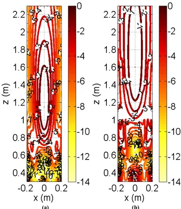
Fig. 1.9 shows the contour plot representation of the antenna power density in a plane orthogonal to the antenna aperture (y=0), for both the NF focused array (Fig. 1.9a) and the corresponding EPA (Fig. 1.9b). The power density is normalized with respect to its maximum value. The -3 dB spot width of the near-field focused array in the transverse direction (x-axis) is approximately 20 cm and the power density apparently decays more rapidly than that of the corresponding EPA. The above spot width is in agreement with the theoretical value (r0/L)x0.886=20.7 cm given in [42].
(a) (b)
Fig. 1.9 - Contour plot of the simulated normalized power density in a 0.4mx1.7m area on the plane (y=0)
orthogonal to the antenna aperture: (a) 8x8 NF focused array, (b) 8x8 EPA.
1.4.1 Axial power density
The radiated power density along the antenna axis is shown in Fig. 1.10 as a function of the distance from the aperture. A reference curve relevant to the equal phase 8x8 planar array is also reported in the same figure. Both curves are normalized to the
20
value of power density radiated at R=2L2/=10.2 m. In particular, a 1/r2 behavior is observed when z>R=2L2/(far-field region). The depth of focus for the focused array is approximately 1.4 m (from 0.8 m to 2.2 m). The peak of the power density is at around
rmax=1.15 m. It is worth noting that for a given power density in the far-field region, the
NF focused array radiates a power density peak which is more around 6 dB greater than that for the EPA, which will result in a larger incident field impinging on the tag to be tracked.
Fig. 1.10 - Simulated radiated power density vs. the distance from the aperture along the axial direction for the
8x8 NF focused array (continuous line) and for the 8x8 EPA (dashed line).
1.4.2 Transverse power density
A 3D view and the contour plot representation of the power density evaluated in a transverse plane at a distance of 1.5 m from the antenna aperture are reported in Fig. 1.11 and Fig. 1.12, respectively. The power density is normalized with respect to its maximum, which occurs at the central point. The -3 dB contour curve of the focused array exhibits a diameter of about 20 cm. The circular symmetry of the contour curves between 0 dB and -9 dB confirms the good quality of the achieved performance. In the 3mx3m area the side lobe level is less than -12 dB (as also shown more clearly in Fig. 1.13).
Fig. 1.11 - Simulated normalized power density in a 3mx3m square area at a distance of 1.5 m from the
21
Fig. 1.12 - Contour plot of the simulated normalized power density in a 3mx3m square area at a distance of
1.5 m from the antenna aperture (8x8 NF focused array).
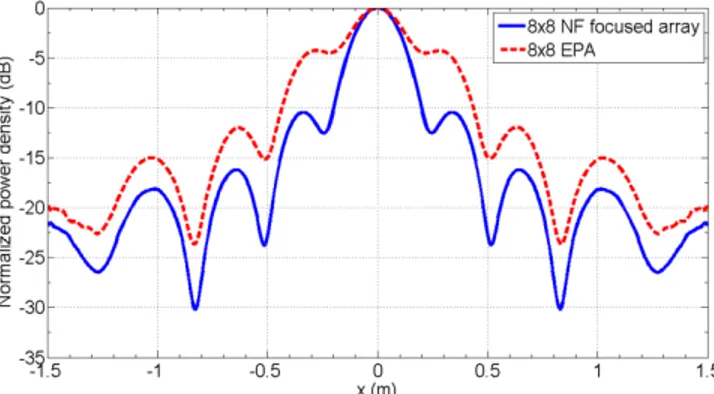
Fig. 1.13 - Simulated normalized power density along the x-direction at a distance of 1.5 m from the antenna
aperture for both the 8x8 NF focused array (continuous line) and the 8x8 EPA (dashed line).
In order to show the focusing effectiveness, the contour plot of the power density radiated at 1.5 m by an 8x8 EPA is shown in Fig. 1.14. The contour curves show that the field amplitude decays more slowly than for the NF focused array. This demonstrates that the EPA does not focus the electromagnetic field in the 3mx3m square spot like the focused one. To verify the circular polarization performance, the calculated AR in a 1.5mx1.5m area of the transverse plane is shown in Fig. 1.15. As apparent, it is less than 2 dB in the -3 dB spot area.
22
Fig. 1.14 - Contour plot of the simulated normalized power density in a 3mx3m square area at a distance of
1.5 m from the antenna aperture (8x8 EPA).
Fig. 1.15 - Contour plot of the simulated axial ratio in a 1.5mx1.5m square area at a distance of 1.5 m from
the aperture (8x8 NF focused array).
Finally, the 3D view and the contour plot of the measured power density radiated by the antenna prototype are presented in Fig. 1.16 and Fig. 1.17, respectively, in a 3mx3m square area at 1.5 m from the antenna aperture. Measurements have been performed at the Yuan Ze University facilities in Taipei, Taiwan, using an NSI 300V-12’x12’ Planar Near Field Scanner System. A good agreement with simulation results in Fig. 1.11 and
23
Fig. 1.12 is apparent. Small discrepancies between simulations and measurements can be reasonably due to antenna prototype manufacturing and alignment errors.
Fig. 1.16 - Measured normalized power density in a 3mx3m square area at a distance of 1.5 m from the
surface of the array prototype.
Fig. 1.17 - Contour plot of the measured normalized power density in a 3mx3m square area at a distance of
1.5 m from the surface of the array prototype.
1.5
Conclusions
The design criteria of a near-field focused microstrip array for RFID readers have been presented. Antenna performance has been analyzed with reference to a specific antenna operating in the 2.4 GHz frequency band. Contour plots for the circularly polarized field close to the antenna aperture (both numerical data and measurements on a prototype) have been provided to demonstrate the effectiveness of the antenna design procedure.
24
Although the size of the proposed antenna is larger than that of commercial RFID antennas, this does not represent a drawback in RFID applications implemented in typical industrial scenarios. From an industrial point of view, the cost of the antenna can be limited by resorting to low-cost laminates, since low-efficiency antennas can be tolerated in such low-power applications. A NF focused antenna represents an intermediate solution between conventional far-field focused array antennas and more expensive and complex phased arrays, namely a satisfactory trade-off between costs and performance improvement. Indeed, it is worth noting that a conventional reader antenna can be simply interchanged with the NF focused antenna here proposed, without requiring any additional control signal or electronic control device.