Benedetta Cappa Marinetti
Artista Futurista
“ Velocità di motoscafo ”
(1919 - 1924)
GREEN PROCESSES BASED ON
SC-CO
2: APPLICATION TO
MATERIALS OF BIOMEDICAL
INTEREST
Unione Europea UNIVERSITÀ DEGLI STUDI DI SALERNO
Department of Industrial Engineering
Ph.D. Course in Chemical Engineering
(XIII Cycle)
GREEN PROCESSES BASED ON SC-CO
2:
APPLICATION TO MATERIALS OF
BIOMEDICAL INTEREST
Supervisors
Ph.D. Student
Prof. Ernesto Reverchon
Lucia Baldino
Dr. Iolanda De Marco
Scientific Referees
Prof. Nicola Maffulli
Dr. Stefano Cardea
Dr. Mariella Fusco
Ph.D. Course Coordinator
Prof. Paolo Ciambelli
Publication list
International journals
Reverchon E., Baldino L., Cardea S., De Marco I., 2012,
Biodegradable synthetic scaffolds for tendon regeneration, Muscles,
Ligaments and Tendons Journal, 2, 181-186.
Cardea S., Baldino L., De Marco I., Pisanti P., Reverchon E.,
2013, Supercritical gel drying of polymeric hydrogels for tissue
engineering applications, Chemical Engineering Transactions, 32,
1123-1128.
Cardea S., Baldino L., Pisanti P., Reverchon E., 2014, 3-D
PLLA scaffolds formation by a supercritical freeze extraction assisted
process, Journal of Materials Science: Materials in Medicine, 25,
355-362.
Baldino L., Cardea S., Reverchon E., 2014, Supercritical
assisted enzymatic membranes preparation, for active packaging
applications, Journal of Membrane Science, 453, 409-418.
Cardea S., Baldino L., Scognamiglio M., Reverchon E., 2014,
3D PLLA/Ibuprofen composite scaffolds obtained by a supercritical
fluids assisted process, Journal of Materials Science: Materials in
Medicine, 25, 989-998.
De Marco I., Baldino L., Cardea S., Reverchon E., 2014,
Production of ethyl cellulose scaffolds by supercritical CO
2phase
separation, Chemical Engineering Transactions, 38, 265-270.
Cardea S., Baldino L., De Marco I., Reverchon E., 2014,
Generation of loaded PMMA scaffolds using supercritical CO
2assisted phase separation, Chemical Engineering Transactions, 38,
241-246.
Baldino L., Cardea S., De Marco I., Reverchon E., 2014,
Chitosan scaffolds formation by a supercritical freeze extraction
process, The Journal of Supercritical Fluids, 90, 27-34.
Baldino L., Cardea S., Reverchon E., 2014, Alginate scaffolds
for vascular application, Journal of Tissue Engineering and
Regenerative Medicine, 8, 457-458.
Reverchon E., Baldino L., Cardea S., 2014, Technical aspects on
biodegradable scaffolds and applications of supercritical fluids
assisted processes, Journal of Tissue Engineering and Regenerative
Medicine, 8, 16.
Campardelli R., Baldino L., Reverchon E., Supercritical fluids
applications in nanomedicine, The Journal of Supercritical Fluids,
in press.
De Marco I., Baldino L., Cardea S., Reverchon E., Supercritical
gel drying for the production of starch aerogels for delivery systems,
submitted to Chemical Engineering Transactions.
Baldino L., Cardea S., Reverchon E., Natural aerogels
production by supercritical gel drying, submitted to Chemical
Engineering Transactions.
Baldino L., Cardea S., Reverchon E., Antimicrobial membranes
produced by supercritical assisted phase inversion, submitted to
Chemical Engineering Transactions.
De Marco I., Baldino L., Cardea S., Reverchon E., Effect of
process parameters on Cellulose Acetate scaffolds morphology
obtained by supercritical CO
2phase inversion, submitted to CRC
Baldino L., Concilio S., Cardea S., De Marco I., Reverchon E.,
Complete glutaraldehyde elimination during chitosan hydrogel drying
by SC-CO
2processing, submitted to Carbohydrate Polymers.
Baldino L., Sarno M., Cardea S., Irusta S., Ciambelli P.,
Santamaria J., Reverchon E., Graphene oxide exfoliation and
purification during the formation of cellulose acetate nanocomposites
by supercritical CO
2assisted phase inversion, submitted to Journal
of Membrane Science.
Baldino L., Cardea S., Maffulli N., Reverchon E., Regeneration
techniques for tendon-to-bone and tendon-to-muscle interfaces
reconstruction, submitted to Tissue Engineering Part B.
Baldino L., Naddeo F., Cardea S., Naddeo A., Reverchon E.,
FEM modeling of the reinforcement mechanism of hydroxyapatite in
PLLA scaffolds produced by supercritical drying, for Tissue
Engineering applications, submitted to Journal of the Mechanical
Behavior of Biomedical Materials.
Book
Baldino L., Maffulli N., Reverchon E., Bone-Tendon Interface,
Regenerative Engineering of Musculoskeletal Tissues and
Interfaces, Eds. Syam Nukavarapu, Joseph Freeman, Cato
Laurencin, 2015, in press.
Proceedings
Baldino L., Cardea S., Reverchon E., Supercritical assisted
enzymatic membranes preparation, 10
thConference on Supercritical
Fluids and Their Applications, Naples April 29 - May 6, 2013 E.
Reverchon & I. De Marco Pag. 261-266 ISBN:88-7897-061-1
ID:4195305.
Cardea S., Baldino L., De Marco I., Scognamiglio M.,
Reverchon E., 3-D PLLA scaffolds formation by supercritical
processing, 10
thConference on Supercritical Fluids and Their
Applications, Naples April 29 - May 6, 2013 E. Reverchon & I. De
Marco Pag. 309-314 ISBN:88-7897-061-1 ID:4195305.
Reverchon E., Della Porta G., Campardelli R., Baldino L.,
Cardea S., De Marco I., Tissue engineering using supercritical fluids
based technology, 1
stScientific workshop on stem cells for ligament
and tendon tissue engineering and regeneration, Pescara April 18,
2013 ISMULT Pag. 1-3 ID:4091653.
Baldino L., Cardea S., De Pascale M.L., Scognamiglio M.,
Reverchon E., 3-D composite scaffolds obtained by a supercritical
fluids assisted process, 14
thEuropean Meeting on Supercritical Fluids,
Marseille May 18-21, 2014.
Reverchon E., Baldino L., Supercritical fluids in nanomedicine,
Translational nanomedicine international meeting, Angers August
27-29, 2014.
Patents
Baldino L., Cardea S., Reverchon E., 2013, “Procedimento per
la produzione di membrane porose caricate con principi
antimicrobici”, VI2013A000285.
Baldino L., Cardea S., Reverchon E., 2014, “Antimicrobically
active packaging, antimicrobically active membrane for packaging
and related uses”, PCT/IB2014/066424.
I
CONTENTS
CHAPTER I. INTRODUCTION ... 1
I.1
Tissue engineering ... 1
I.2
Natural and synthetic polymers for biomedical applications . 3
I.3
Three-dimensional polymeric scaffold fabrication and
different kinds of scaffold... 4
I.3.1
Porous scaffolds ... 5
I.3.2
Hydrogel scaffolds ... 5
I.3.3
Fibrous scaffolds ... 6
I.3.4
Microsphere scaffolds ... 6
I.3.5
Polymer-bioceramic composite scaffolds ... 7
I.3.6
Acellular scaffolds ... 7
CHAPTER II. SUPERCRITICAL ASSISTED PROCESSES VS
TRADITIONAL PROCESSES FOR THE PRODUCTION OF
MATERIALS OF BIOMEDICAL INTEREST ... 9
II.1
Supercritical foaming ... 9
II.2
Supercritical assisted phase separation ... 13
II.3
Processes based on solvent elimination by supercritical CO
2..
... 15
II.3.1
Solvent casting + particulate leaching ... 15
II.3.2
Drying of ionic liquid-polymer mixtures ... 16
II.3.3
Gel drying ... 17
II.4
Electrospinning in supercritical CO
2... 19
CHAPTER III. AIMS OF THE THESIS ... 23
CHAPTER IV. MATERIALS AND METHODS ... 25
IV.1
Materials ... 25
IV.1.1 Cellulose acetate (CA)... 26
IV.1.3 Chitosan ... 26
IV.1.4 Lysozyme ... 26
IV.1.5 Graphene oxide ... 27
IV.1.6 Ibuprofen ... 27
IV.1.7 Hydroxyapatite ... 27
IV.2
Equipment ... 28
IV.3
Supercritical assisted phase separation ... 30
IV.4
Supercritical freeze extraction process ... 30
IV.5
Supercritical gel drying ... 30
IV.6
Analytical methods ... 31
IV.6.1 Field Emission Scanning Electron Microscopy (FESEM) ...
... 31
IV.6.2 Transmission Electron Microscopy (TEM) ... 31
IV.6.3 Structure pore size analysis ... 31
IV.6.4 Structure porosity ... 31
IV.6.5 Differential Scanning Calorimetry (DSC) ... 31
IV.6.6 Thermogravimetric Analysis (TGA) ... 32
IV.6.7 X-Ray Diffraction (XRD) ... 32
IV.6.8 Raman spectroscopy ... 32
IV.6.9 Energy dispersive X-ray spectroscopy (EDX) ... 32
IV.6.10 Fourier Transform Infrared Spectroscopy (FT-IR) ... 32
IV.6.11 Solvent residue analysis ... 32
IV.6.12 Mechanical test ... 33
IV.6.13 In vitro release assay ... 33
IV.6.14 Cells culture ... 33
CHAPTER V. RESULTS AND DISCUSSION ... 35
V.1
Cellulose acetate + Lysozyme ... 35
V.1.1
Enzymatic membranes preparation ... 35
V.1.2
Effect of process parameters on enzymatic membranes
morphology
... 36
V.1.2.1 CA concentration 10% w/w ... 37
V.1.2.2 CA concentration 15% w/w ... 38
III
V.1.2.4 Comments and formation mechanisms ... 43
V.1.3
Other characterizations of CA membranes ... 45
V.1.4
Lysozyme release kinetics and activity ... 47
V.1.4.1 Influence of CA concentration on the kinetics of lysozyme
release ... 48
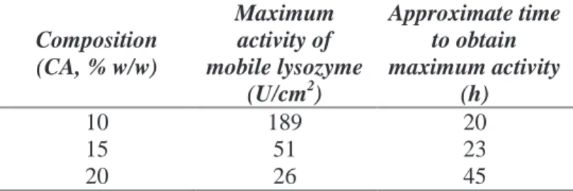
V.1.4.2 Influence of CA concentration on mobile lysozyme activity ...
... 52
V.1.4.3 Immobilized lysozyme activity ... 54
V.1.5
Conclusions ... 56
V.2
Graphene oxide exfoliation and purification during the
formation of cellulose acetate nanocomposites by supercritical CO
2assisted phase separation ... 57
V.2.1
Preparation of CA/GO composite structures ... 57
V.2.2
GO characterization ... 58
V.2.3
Polymer-GO nanocomposites... 61
V.2.4
Conclusions and perspectives ... 70
V.3
3-D PLLA scaffolds formation by a supercritical freeze
extraction assisted process ... 71
V.3.1
Preparation of PLLA scaffolds ... 71
V.3.2
PLLA scaffold: results and discussion ... 71
V.3.3
Conclusions ... 79
V.4
3-D PLLA/Ibuprofen composite scaffolds obtained by a
supercritical fluids assisted process ... 79
V.4.1
Preparation of PLLA composite scaffolds ... 79
V.4.2
PLLA composite scaffold: results and discussion ... 80
V.4.3
Conclusions ... 92
V.5
Chitosan scaffolds formation by a supercritical freeze
extraction process ... 93
V.5.1
Chitosan scaffolds preparation ... 93
V.5.2
Chitosan scaffolds: results and discussion ... 93
V.5.3
Conclusions ... 102
V.6
Complete Glutaraldehyde elimination during Chitosan
hydrogel drying by SC-CO
2processing ... 103
V.6.1
Preparation of Chitosan aerogel ... 103
V.6.2.1 Glutaraldehyde release from Chitosan aerogel ... 106
V.6.2.2 FTIR analysis ... 108
V.6.2.3 TGA analysis ... 109
V.6.3
Conclusions ... 110
V.7
FEM Modeling of the reinforcement mechanism of HA in
PLLA scaffolds ... 111
V.7.1
Preparation of the composite scaffolds ... 111
V.7.2
Experimental results ... 111
V.7.2.1 Effect of HA nanoparticles percentage ... 111
V.7.3
FEM modeling and results ... 116
V.7.3.1 Modeling micrometric porous structure ... 116
V.7.3.2 Modeling the nanofiber network ... 120
V.7.3.3 Modeling of the filler (HA) ... 124
V.7.4
Discussion, conclusions and perspectives ... 127
CHAPTER VI. CONCLUSIONS ... 131
REFERENCES ... 133
V
LIST OF FIGURES
Figure IV.1 Equipment used for the experimentation: (a) Photo, (b) P&ID. ..
... 29
Figure V.1 Section of a CA membrane obtained starting from a 10% w/w
CA solution. Process conditions 150 bar, 55°C ... 37
Figure V.2 Membrane obtained starting from a 10% w/w CA solution
processed at 150 bar, 55 °C: (a) bottom surface; and (b) top surface ... 38
Figure V.3 Section of a CA membrane obtained starting from a 15% w/w
CA solution. Process conditions 200 bar, 45 °C ... 38
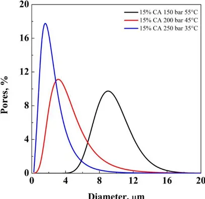
Figure V.4 Pore size distribution in CA membranes obtained starting from a
solution 15% w/w, processed at 55/150, 45/200, and 35/250 T/p ... 39
Figure V.5 Pore size distribution in CA membranes obtained starting from a
solution 15% w/w, processed at 55/200, 45/200, and 35/200 T/p ... 41
Figure V.6 Section of a CA membrane obtained starting from a 20% w/w
CA solution, taken at different enlargements: (a) 250 X; and (b) 1000 X. Process conditions 250 bar, 35 °C ... 42
Figure V.7 Pore size distribution in CA membranes obtained starting from a
solution 20% w/w, processed at 55/150, 45/200, and 35/250 T/p ... 43
Figure V.8 Generic equilibrium diagram CA/acetone/SC-CO2 ... 44
Figure V.9 Thermograms of CA, lysozyme and CA plus lysozyme
membranes processed at 200 bar, 45 °C ... 46
Figure V.10 EDX maps of a membrane at 20% w/w CA processed at 200
bar, 45 °C: (a) Carbon atoms in blue (i.e., CA) and (b) Sulfur atoms in red (i.e., lysozyme) ... 47
Figure V.11 Comparison among lysozyme release kinetics from membranes
at 10, 15, 20% w/w CA, processed at: (a) 250 bar, 35 °C; (b) 200 bar, 45 °C; and (c) 150 bar, 55 °C ... 51
Figure V.12 Comparison among enzymatic activities of mobile lysozyme
from membranes at 10, 15, 20% w/w CA, processed at 200 bar, 45 °C ... 53
Figure V.13 Enzymatic activity of lysozyme immobilized in membranes
processed at 200 bar, 45 °C at: 10%, 15% and 20% w/w CA ... 55
Figure V.14 Immobilized lysozyme activity of 20% w/w CA membrane,
processed at 200 bar 45 °C, when the direct contact with the microorganism was replicated ... 56
Figure V.15 (A,B,D,E,F,G) TEM images of GO at different magnifications,
(C) EDX spectrum taken in the area indicated with D ... 59
Figure V.16 XRD of starting Graphite and of GO (A), GO Raman Spectrum
(B) ... 60
Figure V.17 XPS - C 1s core level for GO ... 60 Figure V.18 TG-DTG-MS profiles for GO ... 61
Figure V.19 CA structures obtained at 200 bar 40 °C starting from 25%
w/w CA/NMP solution: a) macroscopic view, b) FESEM analysis of the section, c) FESEM analysis of the top surface ... 62
Figure V.20 CA/GO structures obtained at 200 bar 40 °C starting from 25%
w/w CA/NMP solution and 3% w/w of GO: a) macroscopic view, b) FESEM analysis of the section, c) FESEM analysis of the top surface ... 63
Figure V.21 CA/GO structures obtained at 200 bar 40 °C starting from 25%
w/w CA/NMP solution and 9% w/w of GO: a) macroscopic view, b) FESEM analysis of the section, c) FESEM analysis of the top surface ... 64
Figure V.22 Pore size distribution in CA/GO composite structures obtained
at different GO loadings ... 65
Figure V.23 TEM image of CA_GO_2_8h at different magnifications ... 66 Figure V.24 TG-DTG-MS profiles for CA (A), CA_GO_1 (B), CA_GO_2
(C), CA_GO_2_8h (D) ... 68
Figure V.25 TG-DTG-MS profiles for GO from CA_GO_2_8h after CA
removal in NMP ... 69
Figure V.26 X-ray diffraction pattern of GO from CA_GO_2_8h, after a CA
removal in NMP (A); Raman Spectra of GO, CA, CA_GO_1, CA_GO_2, CA_GO_2_8h (B) and GO, from CA_GO_2_8h, after a CA dissolution in NMP (C) ... 69
Figure V.27 Sections of PLLA scaffolds obtained starting from solutions at
different polymer concentrations: (a) 5% w/w, (b) 10% w/w, (c) 15% w/w, (d) 20% w/w, phase separated at -30 °C and dried by SC-CO2 at 35 °C and
100 bar ... 72
Figure V.28 Pore size distribution in PLLA scaffolds obtained starting from
different polymer concentrations ... 73
Figure V.29 FESEM image at higher magnification of a 10% w/w PLLA
scaffold, phase separated at -30 °C and dried by SC-CO2 at 100 bar and 35
°C ... 74
Figure V.30 PLLA scaffold surfaces obtained starting from (a) 10% and (b)
20% w/w polymer concentration, processed at 100 bar and 35 °C ... 74
Figure V.31 L209s PLLA scaffold section dried at 100 bar and 35 °C, 15%
w/w PLLA ... 76
Figure V.32 PLLA scaffold skin (20% w/w) obtained drying the structure at
250 bar and 35 °C ... 76
Figure V.33 Qualitative binary diagram for the system PLLA-Chloroform 77 Figure V.34 Qualitative ternary diagram for the PLLA/Chloroform/SC-CO2
system ... 78
Figure V.35 Sections of PLLA/ibuprofen composite scaffolds obtained
starting from solutions at different polymer concentrations: a) 5% w/w, b) 10% w/w, c) 15% w/w, phase separated at -30 °C and dried by SC-CO2 at 45
°C and 150 bar ... 81
VII
Figure V.37 FESEM image at higher magnification of a 15% w/w
PLLA/ibuprofen composite scaffold, phase separated at -30 °C and dried by SC-CO2 at 150 bar and 45 °C ... 83
Figure V.38 PLLA/ibuprofen composite scaffold surfaces obtained starting
from a) 5% w/w, b) 10% w/w, c) 15% w/w polymer concentration, with 10% w/w of ibuprofen, dried at 100 bar and 45 °C by SC-CO2 ... 84
Figure V.39 EDX analysis of PLLA/ibuprofen composite scaffolds obtained
at 150 bar and 55 °C; a) red: Carbon map, b) green: Sodium map ... 85
Figure V.40 PLLA/ibuprofen composite scaffolds obtained at 15% w/w of
PLLA, 35 °C and at different pressures: (a) 100 bar; (b) 200 bar ... 86
Figure V.41 Pore size distributions of PLLA/iburprofen composite scaffolds
obtained at 15% w/w of PLLA, 35 °C and at different pressures (100, 150 and 200 bar) ... 87
Figure V.42 PLLA/ibuprofen composite scaffolds obtained at 15% w/w of
PLLA, 100 bar and at different temperatures: (a) 35 °C; (b) 55 °C ... 88
Figure V.43 Pore size distributions of PLLA/ibuprofen composite scaffolds
obtained at 15% w/w of PLLA, 100 bar and at different temperatures (35, 45 and 55 °C) ... 88
Figure V.44 Ibuprofen release profiles from PLLA scaffolds with different
polymer concentrations (from 5 to 15% w/w) obtained by supercritical drying at 150 bar and 45 °C ... 89
Figure V.45 Skin of 15% w/w PLLA scaffolds obtained at 200 bar and 45
°C, before (a) and after (b) the drug release ... 90
Figure V.46 Ibuprofen release profiles from scaffolds obtained starting from
5% w/w PLLA, at 35 °C and different pressures (a) and starting from 10% w/w PLLA, at 150 bar and different temperatures (b) ... 92
Figure V.47 Effect of chitosan concentration on scaffolds morphology
obtained starting from water:acetic acid ratio 97:3: (a) 2% w/w, (b) 5% w/w, (c) 10% w/w ... 95
Figure V.48 Pore size distribution of chitosan scaffolds obtained starting
from 5 and 10% w/w chitosan solutions with a water:acetic acid ratio of 97:3 ... 96
Figure V.49 Nanofibrous sub-structure of pore walls in 10% w/w chitosan
scaffolds obtained starting from solutions with water:acetic acid ratio of 97:3 ... 97
Figure V.50 Top surface of 10% w/w chitosan scaffolds obtained starting
from solutions with water:acetic acid ratio of 97:3 ... 97
Figure V.51 Effect of acetic acid concentration on chitosan scaffolds
obtained starting from 10% w/w chitosan solutions; water:acetic acid ratio of (a) 99:1 and (b) 95:5 ... 98
Figure V.52 Pore size distribution of chitosan scaffolds obtained starting
from 10% w/w chitosan solutions with different water:acetic acid ratio (99:1, 97:3, 95:5) ... 99
Figure V.53 Qualitative binary phase diagram “polymer concentration vs.
temperature” for the system chitosan/acid water ... 100
Figure V.54 Qualitative modification of binary phase diagram changing
acetic acid concentration ... 101
Figure V.55 hMSCs cultured for 2 (a) and 4 (b) days in osteogenic media.
Live cells (stained green) and dead cells (stained red) on scaffolds obtained starting from 10% w/w of chitosan with 3% v/v of acetic acid ... 102
Figure V.56 FESEM images of Chitosan medium Mw (2% w/w): (a) CH
aerogel section; (b) CH:GTA 16:1 aerogel section; (c) CH:GTA 8:1 aerogel section; (d) CH:GTA 4:1 aerogel section ... 105
Figure V.57 FESEM image of CH:GTA 4:1 aerogel surface ... 105 Figure V.58 GTA release from CH aerogels 2% w/w ... 107 Figure V.59 FTIR spectra of pure CH and CH aerogels, 2% w/w
crosslinked with GTA ... 109
Figure V.60 Thermogravimetric analysis of CH aerogel samples ... 110 Figure V.61 PLLA/HA scaffolds obtained by SC-CO2 drying at 200 bar and
35 °C, with a-b) 10% w/w HA, c-d) 50% w/w HA ... 112
Figure V.62 PLLA scaffolds obtained by SC-CO2 drying at 200 bar and 35
°C, a) 15% w/w PLLA, b) 15% w/w PLLA + 50% w/w HA, c) HA nanoparticles on the bottom of a PLLA micropore, 50% w/w HA ... 114
Figure V.63 HA nanoparticles distribution (measured through the Calcium
atoms distribution - red) along the section of a PLLA scaffold with 30% w/w of HA ... 115
Figure V.64 hcp (left) and fcc (right) close-packing of spheres ... 117 Figure V.65 RVE FEM model (micrometric structure level): a) 3D view; b)
Top view ... 118
Figure V.66 RVE showing a meshed tetrahedral space frame ... 121 Figure V.67 Schematic example of a covered fiber section: on the left,
relation between real fiber and FEM model; on the right, a detail of the contact between HA particles and PLLA fiber ... 125
Figure V.68 Plateau effect of the Young’s modulus with the increasing
weight percentage of HA for a single fiber FEM model... 126
Figure V.69 Explanatory example of a cubic RVE of the nanostructured
model: PLLA (blue elements); HA (yellow elements) ... 127
Figure V.70 Superposition of the numerical results on the experimental
IX
LIST OF TABLES
Table IV.1 Polymers used for the experimentation ... 25 Table IV.2 Solvents used for the experimentation ... 25
Table V.1 Membrane pore size analysis ... 40 Table V.2 Mobile lysozyme activity for CA membranes processed at 200 bar
and 45 °C ... 53
Table V.3 Mean pore size of CA+GO structures obtained at different GO
loadings ... 65
Table V.4 CH and GTA amounts used for the crosslinking reaction ... 103 Table V.5 Maximum GTA concentration measured in the release medium
... 107
Table V.6 Degradation temperature of CH aerogels crosslinked with GTA
... 110
Table V.7 Compressive modulus of PLLA scaffolds obtained with different
XI
Abstract
This research is focused on the production of structures of biomedical interest using supercritical assisted processes: Supercritical freeze extraction, Supercritical gel drying and Supercritical phase separation. These processes have been selected to overcome the limitations of the traditional ones used in this field; indeed, they produce structures with a disordered microporosity, without an organization at nanometric level, with poor mechanical properties and with potential cytotoxic effect due to the residues of organic solvents and crosslinking agents. These problems reduce the efficiency of the cells culture on these structures in terms of adhesion, proliferation and differentiation in the tissue that it would to regenerate.
Therefore, during the experimentation, several polymers, of natural and synthetic origin, were tested for bone, tendon and vascular applications. In particular, in this thesis:
synthetic and natural structures characterized by a micrometric porosity and wrinkled pore walls were produced by Supercritical freeze extraction process,
in the case of polymer/drug composite structures, a homogeneous distribution and controlled release of the active compound was assured,
aerogels starting from natural polymers, that mimic the tissue extracellular matrix at nanometric level were produced by Supercritical gel drying,
bioactive materials were tested; in particular, graphene oxide exfoliation and purification, during the formation of cellulose acetate nanocomposites, was obtained by Supercritical phase separation, FEM Modeling was developed, confirming that mechanical
properties of aerogels depend on how the nanofibrous network is connected in the space and that bending is the major mode of deformation of the network.
CHAPTER I. Introduction
I.1
Tissue engineering
Tissue engineering (TE) is the ensemble of techniques that have been proposed to repair diseased or damaged tissues or to replace and regenerate part of organs of the human body; many of them are still at the stage of research proposal or have moved to the first steps of development.
TE originates from reconstructive surgery used for the direct transplantation of a donor tissue to repair damaged tissues and organs. Many difficulties arise with direct transplantation, due to insufficient number of organ donors, rejection of the donor organ and pathogens transmission. An autogenic tissue transplant (using patient own cells) would address most limitations of the direct transplantation and avoid difficulties concerning rejection and pathogens transmission. Therefore, constructing a tissue-engineered replacement in vitro can be an excellent alternative to the direct transplantation of donor organs (Vacanti et al., 1999; Fuchs et al., 2001).
A crucial step of the in vitro replacement is the scaffold fabrication. An opportunity is to use decellularized tissues and has been largely used to create heart valves, epithelial tissue and blood vessels; however, these “natural” scaffolds suffer of several limitations, among all infections transmission and rejection.
It is also possible to propose scaffolds obtained as 3-D synthetic constructs which serve as temporary support to allow isolated cells to form a new tissue, before being transplanted to the host tissue. These are the structures we will discuss in this thesis. A biodegradable matrix with sufficient mechanical strength, optimized architecture and suitable degradation rate, could perform this objective. The temporary substitution of different biological materials (bones, cartilages, nerves, tendons, vessels, cardiac valves, skin and tissues for the gastrointestinal system) requires different structural characteristics; but, all tissues share a series of common characteristics that have to be simultaneously fulfilled:
• a highly regular and reproducible 3-D structure (macrostructure) similar to the tissue to be substituted;
CHAPTER I
• a very high porosity (exceeding 90%) and, in many cases, a large open pore geometry, that allows cells migration and reorganization (Ma, 2004). Porosity and pore interconnectivity, directly affect the diffusion of nutrients and the removal of metabolic wastes;
• a suitable pore size depending on the specific tissue to be replaced;
• the scaffold should present nano-structural surface characteristics that allow cell adhesion, the proper identification of the extracellular matrix (ECM), proliferation, migration and differentiation. Cells are generally submerged in a collagen matrix characterized by a fibrous nanostructure with fiber diameters ranging between 50 and 500 nm. As a consequence, a similar structure should be formed on the walls of the scaffold to allow cells adhesion and growth (Ma, 2004);
• mechanical properties to maintain the predesigned tissue structure and support the specific loadings applied to the original tissue; the correct values depend on the organs to be repaired;
• biodegradability, biocompatibility and a proper degradation rate, to match the rate of the neo-tissue formation; for this reason, it is very important the choice of the polymer and of its molecular weight, since biodegradability largely depends on these two characteristics;
• absence/reduction of the inflammatory response, mainly due to solvent residues and to degradation products. Chronic inflammation obstacles the neo-tissue formation.
All these specifications are simultaneously required to allow the colonization of the scaffold by stem or specialized cells and all the requirements have to be fulfilled to avoid apoptosis or necrosis of the delicate biological guests.
Many polymers have been tested for TE application. They are commonly divided in natural and synthetic polymers and their characteristics have been discussed in some specific reviews (Gunatillake et al., 2003; Jagur‐Grodzinski, 2006; Puppi et al., 2010).
Several techniques have been proposed for scaffolds fabrication that include: fiber bonding, solvent casting, melt molding, solid free form fabrication, gas foaming, electrospinning and freeze drying, frequently combined with particulate leaching. Details about these processes can be found in specific reviews (Liu et al., 2004; Ma, 2004).
However, conventional scaffold fabrication techniques suffer various limitations; particularly, it is very difficult to obtain simultaneously the macro, micro- and nanostructural characteristics that have been previously described. For example, it is difficult to obtain:
• large porosity together with a control of the pore diameter, of the pore connectivity and of the mechanical resistance;
• large porosity together with the nanometric pore surface that enhances cell adhesion and growth;
Introduction
3 • complex 3-D structures; several techniques are limited to the production of thin disks or films;
• the removal of toxic solvents that are located deep inside the structure. Supercritical carbon dioxide (SC-CO2) assisted processes have been
proposed in this field, starting from some pioneering works on supercritical foaming (Mooney et al., 1996; Harris et al., 1998). Besides SC-CO2 assisted
foaming, various other techniques have been used such as: supercritical assisted phase separation, supercritical gel drying, electrospinning in SC-CO2.
The general aim of SC-CO2 assisted techniques is to improve the
traditional TE processes, using the characteristic properties of SC-CO2 to
control scaffolds morphologies thanks to the modulability of mass transfer properties, characteristic of dense gases and the specific thermodynamic behavior of gas mixtures at high pressure. An efficient solvent elimination can be obtained due to the large affinity of SC-CO2 with almost all the
organic solvents and short processing times are possible, taking advantage of the enhanced mass transfer rates.
I.2
Natural and synthetic polymers for biomedical applications
In biomedical applications, the criteria for selecting the biomaterials are based on their material chemistry, molecular weight, solubility, shape and structure, hydrophilicity/hydrophobicity, water absorption degradation and erosion mechanism.
Polymeric scaffolds are drawing a great attention due to their properties such as high surface-to-volume ratio, high porosity with very small pore size, biodegradation and mechanical properties. They offer advantages of biocompatibility, versatility and the biological properties which are significant in the application of TE and organ substitution. Naturally occurring polymers, synthetic biodegradable, and synthetic non-biodegradable polymers are the main kinds of polymers used as biomaterials.
Natural polymers can be considered as the first biodegradable biomaterials used clinically (Nair et al., 2007). Natural materials have better interactions with the cells that allow them to enhance the cells’ performance in biological system. They can be classified as proteins (silk, collagen, gelatin, fibrinogen, elastin, keratin, actin and myosin), polysaccharides (cellulose, amylose, dextran, chitin and glycosaminoglycans), or polynucleotides (DNA, RNA) (Ozdil et al., 2014).
Synthetic polymers are highly useful in biomedical field since their properties (e.g., porosity, degradation time and mechanical characteristics) can be tailored for specific applications. Synthetic polymers are often cheaper than biologic scaffolds; they can be produced in large uniform quantities and have a long shelf time. Many commercially available synthetic polymers show physico-chemical and mechanical properties
CHAPTER I
comparable to those of biological tissues. They exhibit, in general, predictable and reproducible mechanical and physical properties such as tensile strength, elastic modulus and degradation rate (Gunatillake et al., 2006). PLA, PGA, and PLGA copolymers are among the most commonly used synthetic polymers in TE (Ma, 2004). PHA belongs to a class of microbial polyesters and is being increasingly considered for applications in TE (Chen et al., 2002).
Bioactive ceramics, such as HA, TCP and specific compositions of silicate and phosphate glasses (bioactive glasses) and glass-ceramics (such as apatite-wollastonite) react with physiological fluids and through cellular activity form tenacious bonds to hard and in some cases soft tissue engineering (Hench, 1991). However, their biocompatibility and biodegradability are often insufficient, limiting their potential use in the clinical side. It is possible to overcome these issues by blending synthetic and natural polymers or by using composite materials that improve the scaffold properties and thereby allowing controlled degradation (Cascone et al., 2001) and improving the biocompatibility in biomedical applications (Ciardelli et al., 2005).
I.3
Three-dimensional polymeric scaffold fabrication and
different kinds of scaffold
In an era of decreasing availability of organs for transplantation and a growing need for suitable replacements, the emerging field of TE gives hope to patients who require tissue and organ substitutes. Since 1980, researchers developed many novel techniques to shape polymers into complex architectures that exhibit the desired properties for specific TE applications. Typical scaffold designs included meshes, fibers, sponges and foams and so forth. These designs are chosen since they promote uniform cell distribution, diffusion of nutrients and the growth of organized cell communities (Freed et al., 1998). Most techniques involve the application of heat and/or pressure to the polymer or dissolving it in an organic solvent to mold the material into its desired shape. While each method presents distinct advantages and disadvantages, the appropriate technique must be selected to meet the requirements for the specific kind of tissue.
To repair and regenerate lost or damaged tissue and organs, 3D scaffolds must be designed, fabricated, and utilized to regenerate the tissue similar in both anatomical structure and function to the original tissue or organ to be replaced or repaired. Therefore, different kinds of scaffold, including porous scaffold, microsphere scaffold, hydrogel scaffold, fibrous scaffold, polymer-bioceramic composite scaffold and acellular scaffolds have been developed.
Introduction
5
I.3.1 Porous scaffolds
Sponge or foam porous scaffolds have been used in TE applications (Zhang et al., 1999), especially for growth of host tissue, bone regrowth, or organ vascularization. Their porous network simulates the ECM architecture allowing cells to interact with their environment. Though foams and sponges are more mechanically stable compared to mesh structures, their use is still limited due to the open spaces present throughout the scaffold. A foam polymeric scaffold approach has several potential advantages for proliferating or adherent cell lines such as: (a) provide a physical surface onto which the cells can lay their own ECM, (b) may inhibit cell growth of adherent contact-inhibited cells, (c) provides improved nutrient transport to the center of the device through the porous interconnecting channel network, and (d) may limit cluster size to the pore size of the foam and thereby eliminating very large clusters that can potentially develop a necrotic center. Depending on the choice of solvent and phase separating conditions, the foams can be controlled to form either random or oriented pore architectures (Ma et al., 2001b) and ideal pore sizes vary for different cells and tissues (Wei et al., 2004).
I.3.2 Hydrogel scaffolds
The design and application of biodegradable hydrogels has dramatically increased the potential impact of hydrogel materials in the biomedical field and enabled the development of exciting advances in controlled drug delivery and TE applications (Cabodi et al., 2005). Hydrogels, comprised of naturally derived macromolecules, have potential advantages of biocompatibility, cell-controlled degradability and intrinsic cellular interaction. They may exhibit batch variations and generally exhibit a narrow and limited range of mechanical properties. In contrast, synthetic polymers can be prepared with precisely controlled structures and functions.
Hydrogels in TE must meet a number of design criteria to work appropriately and promote new tissue formation. These criteria include both physical parameters (e.g., degradation and mechanics) as well as biological performance parameters (e.g., cell adhesion). Biocompatible hydrogels are currently used in cartilage wound healing, bone regeneration, wound dress and as carriers for drug delivery (Peppas et al., 1993). They are often favorable for promoting cell migration, angiogenesis, high water content and rapid nutrient diffusion (Bryant et al., 2001).
CHAPTER I
I.3.3 Fibrous scaffolds
The development of nanofibers enhanced the scope for fabricating scaffolds that can potentially mimic the architecture of natural human tissue at the nanometer scale.
Currently, there are three techniques available for the synthesis of nanofibers: electrospinning, self-assembly and phase separation. Electrospinning is the most widely studied technique and also seems to exhibit the most promising results for TE applications. The high surface-area-to-volume ratio of the nanofibers combined with their microporous structure favors cell adhesion, proliferation, migration and differentiation, all of which are highly desired properties for biomedical applications (Bhattarai et al., 2004; Ma et al., 2005). Nanofibers used as scaffolds for musculoskeletal TE including bone, cartilage, ligament and skeletal muscle, skin, vascular, neural TE and as vehicle for the controlled delivery of drugs, proteins and DNA (Vasita et al., 2006). The blending technique is a common choice for the nanofiber functionalization. However, most of the polymer nanofibers do not possess any specific functional groups and they must be specifically functionalized for successful applications. The most popular and simplest nanofiber modification methods are physical blending and coating. Surface grafting polymerization has also been used for attaching ligand molecules and adhesive proteins on nanofiber surface for application of affinity membrane and TE scaffold, respectively.
I.3.4 Microsphere scaffolds
Microsphere scaffolds are largely used as drug delivery systems and in advanced TE applications such as gene therapy, antibiotic treatment of infected bone and so forth (Stephens et al., 2000). The influence of nanotechnology on scaffold design and the possibility of sustained release formulations of growth factors via microspheres are showing promising developments.
Microsphere scaffolds are generally a polymer matrix used for drug encapsulation for the release of drugs at a relatively slow rate over a prolonged period of time (Berkland et al., 2002). They offer several benefits, including ease of fabrication, control over morphology, physico-chemical characteristics and versatility of controlling the release kinetics of encapsulated factors (Berkland et al., 2003). The methods used to produce microsphere-based scaffolds utilized heat sintering (Borden et al., 2004; Yao et al., 2005), solvent vapor treatment (Jaklenec et al., 2008a; Jaklenec et al., 2008b), solvent/nonsolvent sintering method (Nukavarapu et al., 2008) or nonsolvent sintering technique (Singh et al., 2008).
Introduction
7
I.3.5 Polymer-bioceramic composite scaffolds
Development of composite materials for TE is attractive since their properties can be engineered to suit the mechanical and physiological demands of the host tissue by controlling the volume fraction, morphology and arrangement of the reinforcing phase (Rezwan et al., 2006). Ceramics used in fabricating implants can be classified as nonabsorbable (relatively inert), bioactive or surface reactive (semi-inert) (Hench, 1993), and biodegradable or resorbable (non-inert) (Hentrich et al., 1971).
Ceramics are known for their good compatibility, corrosion resistance and high compression resistance. Drawbacks of ceramics include brittleness, low fracture strength, difficulty to fabricate, low mechanical reliability, lack of resilience and high density. In recent years, researchers realized that ceramics and their composites can also be used to augment or replace various parts of body, particularly bone. The ceramics used for the latter purposes are classified as bioceramics. The combination of polymers and inorganic phases leads to composite materials with improved mechanical properties due to the inherent higher stiffness and strength of the inorganic material. Secondly, addition of bioactive phases to bioresorbable polymers can alter the polymer degradation behavior of the scaffolds (Blaker et al., 2003; Kim et al., 2005). Complications in the development of polymer bioceramics composite scaffold are: (i) maintenance of strength and the stability of the interface during the degradation period and replacement by the natural host tissue and (ii) matching resorption rates to the repair rates of body tissues developed for hard tissue implants and TE scaffolds, due to their excellent biocompatibility, bioactivity, and bioresorption in calcified tissue. The composite scaffolds support uniform cell seeding, cell ingrowth and tissue formation.
I.3.6 Acellular scaffolds
Acellular tissue matrices can be prepared by manufacturing artificial scaffolds or by removing cellular components from tissues by mechanical and chemical manipulation, to produce collagen-rich matrices (Dahms et al., 1998; Yoo et al., 1998; Chen et al., 1999). These matrices slowly degrade on implantation and are generally replaced by the ECM proteins secreted by the ingrowing cells. The ultimate goal of any decellularization protocol is to remove all cellular material without adversely affecting the composition, mechanical integrity and eventual biological activity of the remaining ECM. Since the structures of the proteins (e.g., collagen and elastin) in acellular matrices are well conserved and normally arranged, the mechanical properties of the acellular matrices are not significantly different from those of native bladder submucosa (Dahms et al., 1997).
CHAPTER I
Although various synthetic biodegradable polymer scaffolds have been developed and improved by mimicking biological structures, comparing to other scaffolds, acellular scaffolds have the following advantages:
(i) retain their correct anatomical structure even after the decellularisation process;
(ii) retain native ECM architecture and possess the cell adhesion ligands; (iii) the decellularisation process reduces immunological responses by completely removing cellular components;
(iv) the decellularisation process facilitates similar biomechanical properties as those of native tissues that are critical for the long-term functionality of the grafts.
Various extracellular matrices have been utilized successfully for TE in animal models and products incorporating decellularized heart valves, small intestinal submucosa (SIS) and urinary bladder received regulatory approval for use in human patients (Gilbert et al., 2006).
CHAPTER II. Supercritical
Assisted Processes vs Traditional
Processes for the Production of
Materials of Biomedical Interest
II.1
Supercritical foaming
Traditional foaming techniques use a chemical agent that produces the gaseous compounds responsible of the formation of bubbles that, blocked into the polymer, produce a foam (Meng et al., 2004). Foaming process is, in principle, simple and it is possible to achieve a relative control of pore diameter by calibrating the process parameters. However, it tends to produce prevalently closed pores structures; indeed, its standard industrial application is in thermal and acoustic insulation.
The supercritical homologous of this process uses SC-CO2 to produce
microcellular foams when released from the polymer. The main requirement of SC-CO2 foaming process is that CO2 should be dissolved in a sufficient
amount in the polymer; this characteristic excludes, for instance, the use of polymers which have a low affinity for CO2.
When compared to traditional foaming processes, SC-CO2 based
technique is characterized by larger mass transfer coefficients and by the tunability of the quantity of CO2 dissolved in the polymer, via pressure and
temperature variations; moreover, this process is solventless.
Supercritical foaming is based on the following steps: first, the polymer is saturated with the supercritical fluid at high pressure; second, the polymer/gas mixture is quenched into a supersaturated state by either reducing pressure or increasing temperature: bubble nucleation is produced; third, growth of the gas cells formed throughout the polymer sample is obtained. The driving force for bubble nucleation and growth is the temperature difference T-Tg that is controlled changing the temperature by
CHAPTER II
Other process parameters that influence foam characteristics are the depressurization rate and the cooling velocity.
In the first applications of SC-CO2 foaming, prevalently closed structures
were obtained (Goel et al., 1994; Arora et al., 1998; Stafford et al., 1999; Reverchon et al., 2007a). This technique was used to produce foams of various polymers as poly(ether imide) (Krause et al., 2002), poly(ether sulfone) (Krause et al., 2002), atactic polystyrene (Stafford et al., 1999), poly(methyl methacrylate) (Goel et al., 1994), poly(ethylene-covinylacetate) (Jacobs et al., 2004) and the effect of process parameters such as saturation pressure, processing time and temperature were in some cases investigated. For example, Reverchon and Cardea (Reverchon et al., 2007a)proposed the foaming of polystyrene by SC-CO2, obtaining very regular cellular
structures. These authors also showed that the classical foaming theory could be applied also to the supercritical assisted process; in particular, two factors should be met during the depressurization step for generating uniform foams: the absorption of a sufficient amount of CO2 to let pores nucleation
and growth during the depressurization and the Tg of the polymer should be
lower of the temperature used in the experiment. This second condition is also favored by Tg depression due to CO2 adsorption.
Supercritical foaming has also been used to produce open-pore structures suitable for TE applications. This possibility was first proposed by Mooney et al. (Mooney et al., 1996). They claimed that PLGA open porous structures could be obtained by this process, avoiding the use of organic solvents. The same research group (Harris et al., 2001) in a subsequent work added to CO2-foaming process a solid porogen (foaming/particulate leaching
technique) to overcome the limited pore connectivity. There was no quantitative information about the obtained pores connectivity; but, the attempts of cultivating muscle cells for adhesion and proliferation put in evidence as an adequate cells growth was measured only on foam surfaces. Similar results were obtained by Sheridan et al. (Sheridan et al., 2000)using various polymers and testing angiogenic factors delivery. Barry et al. (Barry et al., 2006) prepared methyl-methacrylate structures by SC-CO2 foaming,
claiming that the degree of porosity and interconnectivity of the scaffolds can be controlled simply by modifying the depressurization rate of the process: scaffolds with a porosity around 81% and with good connectivity (57% open pores) were obtained according to these authors. Another typical characteristic of the foaming process is the formation of a continuous skin on the external surfaces; these authors tried to overcome this problem removing the foam skin; then, chondrocytes proliferation was studied, confirming an adequate adhesion and growth on the foams surface. Singh et al. (Singh et al., 2004)used this process for PLGA foams generation; the authors claimed a large percentage of interconnected pores but field emission scanning electron microscope (FESEM) images proposed in this work, showed a
Supercritical Assisted Processes vs Traditional Processes for the Production of Materials of Biomedical Interest
11 between the two experimental evidences could be related to the presence of very small interconnection that are not evident in FESEM images; however, the interconnections useful for TE are the larger ones that should allow cells migration within the scaffold. Subsequently, Barry et al. (Barry et al., 2005) tested other non-degradable polymers using the same procedures of a previous work (Barry et al., 2006); again the authors indicated a large open pores percentage; but, FESEM images suggest that prevalently not largely connected structures were formed. In this case, neuroblastoma cultivation was proposed for some days (4-5) and the spread of the cells on the foam structure was observed. Mathieu et al. (Mathieu et al., 2005) prepared bioresorbable ceramic-polymer composites using mixtures of PLA and ceramic compounds such as HA and TCP. The effect of process parameters was analyzed: slower cooling rates induced larger and more interconnected pores; ceramic particles tended to distribute on the pore walls of composite foams. The foams were also characterized by a mechanical point of view: higher compression resistance for composite structures was measured. Moreover, stem cells spread (after 2 weeks) on foams surface and moved across pores; they also started to differentiate in osteoblast lineage. An explanation of pores interconnection was also attempted: at lower viscosity, pores can grow for a longer time and pore walls have time to break, creating interconnections; however, only partial interconnection was observed and measured. Using ceramic fillers, more heterogeneous structures were obtained. Mathieu et al. (Mathieu et al., 2006)processed the same composite to evidence anisotropy in foams morphology with pores oriented in the foaming direction. This characteristic could be useful in some TE applications where largely oriented tissue have to be regenerated. This anisotropy was also found in the mechanical behavior of the foams. Other authors (Jenkins et al., 2006) applied SC-foaming technique to PCL. The effect of the depressurization time on the final microstructure of the foam was studied: it resulted in a combination of open and closed pores. The most interesting result was that, due to the partial (up to 70%) crystallization of the PCL foams, the inner surface presented a microtexture on pore surfaces; whereas, as a rule, foams present only smooth internal surfaces (Goel et al., 1994). This characteristic could be of interest for cell adhesion. Tai el al. (Tai et al., 2007) tested SC-foaming on PLGA copolymers of various composition and molecular weight. The effect of various processing parameters was studied (mainly temperature, pressure and processing times); again, partly interconnected structures were obtained, with non-porous skins. Luetzow et al. (Luetzow et al., 2007)loaded PCL foams with a small model molecule. The main scope was to understand if molecules can be loaded in the polymeric structure and if their presence modifies the foam. Up to 43% w/w of this compound was loaded in the SC-CO2 foamed polymer and
crystals of dimensions up to about 3 mm were formed, that largely modified the structure. Velasco et al. (Velasco et al., 2010)prepared partly degradable
CHAPTER II
PMMA + PLA structures by SC-CO2 foaming and tried to incorporate
ibuprofen. As in other SC-foaming works, they obtained a dense outer skin and a relative pores interconnectivity up to 64%. Cell culture was also attempted using human fibroblasts that were examined by FESEM. Ibuprofen was partly extracted during the process since it is partly soluble in SC-CO2, as stated by the authors. The structures showed a good cells
adhesion and proliferation after 7 days of culture.
Other authors tried to couple supercritical foaming with particulate leaching to induce the massive formation of open pores structures. The idea is that adequate quantities of a leachable material could contribute in breaking pore walls. Kim et al. (Kim et al., 2006) produced PLGA/HA composite scaffolds by gas foaming + particulate leaching. Disks of 100-200 µm thickness, containing HA nanoparticles were generated using 90% w/w NaCl particles as pore opener. They obtained a highly open pore structure with no evidence of external non-porous layer and with an average compressive modulus of 4.5 MPa. Cells culture using rat calvarial osteoblasts was tested: an adhesion percentage of about 66% and osteoblasts growth in 4 weeks, corresponding to about 85% of cells increase, were obtained. They also attempted in vivo implantation of the osteoblast-seeded PLGA scaffolds and 8 weeks after the implantation they observed the formation of bone lamellar structures in the case of HA containing scaffolds. Salerno et al. (Salerno et al., 2008) applied gas foaming plus microparticles leaching to PCL loaded with high quantities of NaCl microparticles (about 5 µm in diameter) and particularly concentrated their attention on 30/70 and 20/80 w/w PCL/NaCl composites. Subcritical CO2 (65 bar) was used as the
foaming agent. The large quantity of NaCl influenced the foaming process restricting the pores expansion, due to the increase in the composite stiffness; therefore, foams showed a decrease of pore size with NaCl percentage increase. Using microparticles concentration gradients, these authors were also able to induce a porosity gradient in the PCL structures. They induced about 100% open pores formation in PCL foams, starting at about 40% w/w NaCl. On the other hand, no quantitative indication were given about the mechanical properties of the structures after the leaching step, that could be influenced by the very high quantity of loaded microparticles. Mou et al. (Mou et al., 2011)tested PLGA plus collagen plus HA by SC-foaming of tablets of different composition. They found that the expansion factor of the mixture decreased with the amount of collagen and HA; the influence of collagen was the most significant. Then, using 2.5% HA and 2.5% collagen, tested the effect of various process parameters like temperature, pressure and saturation time, measuring the average pore size and porosity. Mean pore sizes between 100 and 700 µm were observed and porosities ranging between about 48 and 92% were measured; however, no clear distinction between open and closed pores was presented. Cell
Supercritical Assisted Processes vs Traditional Processes for the Production of Materials of Biomedical Interest
13 osteoblasts distributed throughout the foam as shown by FESEM and fluorescence images. This information was confirmed by chemical assays.
A particular and interesting application of dense CO2 assisted foaming
was presented by Dehghani and coworkers (Annabi et al., 2009; Annabi et al., 2010; Ji et al., 2011). They were able to induce controlled foaming of elastin, elastin + tropoelastin and chitosan hydrogels, allowing CO2
saturation, followed crosslinking under pressure. Chemical crosslinking (glutaraldehyde) was used to stabilize the hydrogel; then, the system was depressurized with the generation of bubbles that induced gas foaming. This process enhanced the porosity of the final structure, with respect to atmospheric pressure processing and was successful at lower temperatures (down to 4 °C in the case of chitosan) with the production of pores with average diameters ranging between about 25 and 80 µm depending on the biopolymer used. At higher temperatures T > 23 °C non-porous structures were obtained for chitosan due to the faster crosslinking of the hydrogel. Cells seeding (fibroblasts) on the hydrogels produced by the dense CO2
assisted process was performed and their migration and growth was enhanced with respect to traditionally processed materials.
Summarizing, foaming process application to TE has the advantages that it is a very simple process and generally no solvents are required. On the other hand, the control of sample dimensions and shape is not easy, due to the large volume increase produced by foaming process and non-porous external skins can be generally formed. There is commonly a lack of interconnectivity between pores, that some authors tried to overcome using a massive microparticles loading (Salerno et al., 2008; Salerno et al., 2010)or blending with a second phase formed by a harder material, to break pores wall. Correspondingly, the structures obtained possess lower mechanical properties. The nanofibrous internal structure, that should mimic the natural ECM, is absent in this process; only when the polymer crystallization superimposes to foaming, rough internal pore surfaces can be produced that favor cells adhesion.
II.2
Supercritical assisted phase separation
Phase separation (PS) is obtained when a system formed by a polymer and a solvent becomes thermodynamically unstable and tends to separate into two phases: a polymer-rich and a polymer-lean phase. During the solvent removal, the polymer-rich phase solidifies. PS can be induced in several ways (Van de Witte et al., 1996a); the two main techniques adopted are: thermal induced phase separation (TIPS) and solvent induced phase separation (SIPS). The most common process is the SIPS in which the polymer solution is casted on an inert support, that is, then, immersed into a bath filled with a second solvent in which the polymer is not soluble, but,
CHAPTER II
forms a solution with the polymer solvent. The contact between the two solvents causes the formation of a liquid solution, followed by the phase separation with the formation of several different possible structures (Van de Witte et al., 1996a). If process conditions have been properly selected, micrometric open pore structures are formed and, in some cases, non-porous skins are formed. These structures have been largely used as membranes (Van de Witte et al., 1996a). PS processing is relatively simple, but, some limitations are present such as limited versatility in solvents combination, long processing times due to several post-treatments to wash the structure and the presence of residual solvents in the final product.
Phase separation techniques have been proposed to produce (prevalently bi-dimensional) scaffolds for TE applications (Lo et al., 1995; Schugens et al., 1996; Nam et al., 1999). For example, the preparation of PLA biodegradable interconnected microcellular structures has been reported (Schugens et al., 1996). Nam et al. (Nam et al., 1999) found that isotropic open porous PLA scaffolds can be obtained by a coarsening effect in the TIPS process and tested the introduction of surfactants that act as porogen to enhance the pore size. The formation of PLGA scaffolds containing bioactive molecules has been also tested (Hua et al., 2002).
The supercritical modification of the phase inversion process is based on the use of SC-CO2 as the non-solvent. This alternative can overcome some
limitations of the traditional processes. SC-CO2 can dry the polymer rapidly,
due to the enhanced mass transfer properties typical of supercritical fluids; moreover, the structure can be obtained without additional post-treatments, since the solvent used to dissolve the polymer is completely extracted. It is easy to recover the liquid solvent, since it dissolves in SC-CO2 and can be
removed from gaseous CO2 by depressurization. SC-CO2 processing allows
to modulate the structure morphology and pore size changing pressure and temperature. Supercritical assisted phase separation (SC-PS) has been proposed for the formation of polymeric membranes to be used for several applications such as filtration processes (Cardea et al., 2006), catalysis (Cardea et al., 2011), drug controlled release (Reverchon et al., 2006c; Duarte et al., 2009b; Temtem et al., 2009; Cardea et al., 2010), etc.
The most relevant parameters in membranes formation by SC-PS resulted: polymer concentration, pressure, temperature and solvent type. In some cases, other process parameters have also been investigated such as the depressurization rate and the addition of another polymer in the starting solution (Temtem et al., 2008). Depending on the process conditions and on the kind of polymer used, the four main morphologies characteristic of the conventional phase inversion were observed even on the same polymer (Reverchon et al., 2004; Xu et al., 2005; Reverchon et al., 2006a; Reverchon et al., 2007b; Temtem et al., 2008). At given process conditions it is possible to observe dense, cellular and bicontinuous structures and particulate