Chapter 1
Literature Review
1.1 Working principles of gas turbine engines
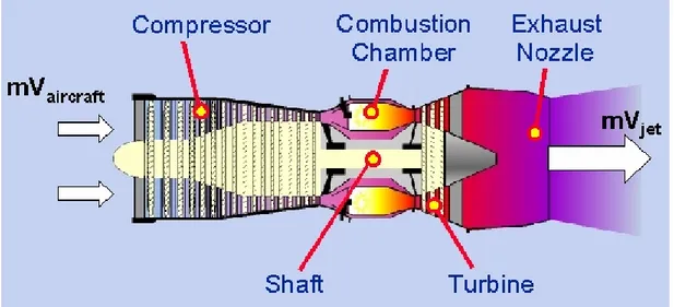
Jet propulsion is a practical application of Newton’s third law motion which states that ‘for every force on a body there is an opposite and equal reaction’. For aircraft propulsion the ‘body’ is atmospheric air that is accelerated as it passes through the engine. The force required to give this acceleration has an equal effect in the opposite direction acting on the apparatus producing the acceleration. Thus, a jet engine is fundamentally a devise designed to accelerate a stream of air or gas and to expel it at high velocity (Fig. 1.1). This can be done in several ways and the technique adopted by the engine to supply and convert the energy into power for flight characterizes the different types of engines. Nowadays, jet propulsion is popularly linked to the gas turbine engine even though this is only one of the many kinds of jet propelled engine; its fame probably depends on the fact that its design allowed to overcome the weaknesses of the earlier jet propulsion engines.
The patent for using a gas turbine to produce a propulsive jet dates back to 1930 but, only eleven years later, Frank Whittle saw his engine completing its first flight. After some years of military application, at the end of the 1960's, commercial jets were accepted, and by the end of the 1980's, the commercial aviation market overtook the military one (Rolls-Royce plc, 1986a).
1.1.1 Outlook on working cycle and airflow
The gas turbine engine’s mechanical arrangement is simple in principle: it consists of two main rotating parts, a compressor and a turbine, and one or a number of combustion chambers (Fig. 1.2). However the thermo and aerodynamic aspects of the engine give rise to some non trivial issues mainly depending on:
• the high operating temperatures in the combustion chamber and turbine • the effects of varying flows across the compressor and turbine blades • the design of the exhaust systems through which the gases are ejected to
form the propulsive jet.
Fig. 1.2: Basic jet engine layout (Cervenka, 2000).
The gas turbine engine and the four-stroke piston engine have a similar working cycle: examination of both of the cycles show that in each instance there is
induction, compression, combustion and exhaust. They differ in the fact that
these processes are intermittent in the piston engine whilst they occur continuously in the gas turbine.
Besides, in the turbine engine the pressure of the gas during combustion does not rise (like that of the piston engine) because the chamber is not an enclosed space, but its volume increases.
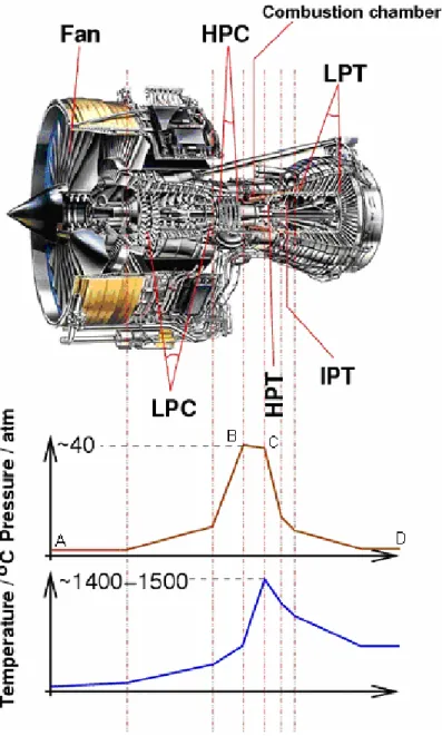
Fig. 1.3 shows the trend of pressure and temperature during a working cycle upon which the gas turbine engine operates. In the largest part of the modern aero engines the first component downstream of the intake is the fan which is a large propeller whose function is to split the flow into a first part pumped into the compressor and a second part which provides air to join the main flow after the turbine. The separation of the flow allows the reduction of the noise of the engine and reduction of the specific fuel consumption. Point A represents air at atmospheric pressure that is compressed along the line AB. From B to C heat is added to the air by introducing and burning fuel at constant pressure, thereby considerably increasing the air volume. Pressure losses in the combustion
chambers are indicated by the drop between B and C. From C to D the gases resulting from combustion expand through the turbine and jet pipe back to atmosphere. During this part of the cycle, a certain amount of the energy supplied by the expanding gases is turned into mechanical power by the turbine, which has the task of providing the power to drive the compressor; the remainder, on its discharge to atmosphere, provides the thrust (Rolls-Royce plc, 1986b).
Fig. 1.3 A jet engine section (Rolls-Royce Trent 800) showing the different stages (low pressure compressor - LPC, high pressure compressor - HPC, high pressure turbine - HPT, intermediate pressure turbine - IPT, low pressure turbine - LPT),
1.1.2 Cooling
The turbo engine is a heat engine hence the higher the combustion temperature the greater the expansion of the gases and, consequently, the higher the thermal efficiency. During service, however, it is fundamental to ensure that certain parts of the engine, specially combustor and turbine, do not absorb heat to the extent that is detrimental to their safe operation. Continuous cooling of these components allows to overcome this problem. In particular, turbine blades cooling consists of the adoption of a cooling airflow which is provided by the engine internal air system, defined as those airflows which do not directly contribute to the engine thrust. This air, that can reach one fifth of the total engine core mass airflow, raises its pressure and temperature as it progresses through the compressor; therefore, in order to reduce engine performance losses, the air is taken as early as possible from the compressor according to the requirement of each particular function. The internal air system cooling, in fact, has several functions: among these engine anti-icing, prevention of hot gas ingestion into the turbine disc cavities, control of turbine blade tip clearances are some examples (Rolls-Royce plc, 1986c).
1.1.2.1 Turbine blade cooling
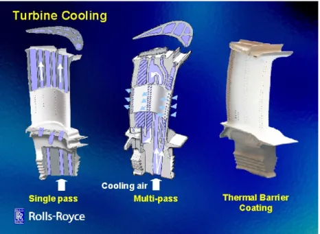
Throughout the gas turbine history numerous cooling methods have been used: from single pass internal cooling (the airflow passes through channels in the turbine blade bulk) to single pass internal cooling with external air film cooling and finally multi-pass internal cooling with external air film cooling (Fig. 1.4). The working principle of such film cooling is to discharge spent cooling air out on the airfoil surface to provide a buffer between the airfoil surface and the hot mainstream gas flow. Since the heated cooling air is significantly cooler than the mainstream gas flow, reduction in the heat load and metal temperatures are obtained.
In order to maximize the film cooling benefit, small sized holes (0.2-0.5 mm diameter (Rigney, Viguie, Wortman, and Skelly, 1995)) are required to distribute the convectively spent cooling air flow along the entire airfoil surface. Further, the area of these small film holes regulates the amount of cooling flow used in the airfoil for both convective and film cooling. Therefore any closure of these holes can result in large cooling flow reduction that deleteriously affects the durability of the coated airfoil (Schulz, Leyens, Fritscher, Peters, Saruhan-Brings, Lavigne, Dorvaux, Poulain, Mévrel, and Caliez, 2003). This is the reason why the hole size distribution is a crucial issue also when considering the blade coating processes. Depending on the coating deposition method, in fact, such surface treatment could reduce in size and number the effective holes with a detrimental effect on the airflow cooling efficiency.
1.2 Competitiveness and environmental impact
Competitiveness and environmental impact are important consideration at the design stage of a gas turbine engine, whether aero, industrial or marine. It has to be not only reliable, economical on fuel and profitable but also environmentally acceptable. The main concern is about the emissions of carbon dioxide and nitrogen oxides.
In the last 25 years developments in technology have led directly to a doubling of the efficiency of civil aero-engines, with an increase of 20% in the last 10 years. Similarly, the aero-engines NOx emissions have been reduced by more than 20%
and the CO2 emissions have been decreased by 50%. The result is that aviation
now only contributes 3.5% of the totality of greenhouse gases caused by human activities. Nevertheless, the industry is committed to strongly invest in developing technologies to meet increasingly tougher emissions regulations. Thus, the near term aim (2008) is a further reduction of 12% in CO2 emissions and 60% in NOx
emissions relative to International Civil Aviation Organization (ICAO) 1996 standards (Pickard, 2001), (Europe's aeroengine community targets major environmental improvements, 2000).
For this aim to be achieved, future aircraft gas turbine engines must provide increasing cycle performance at reduced weight (i.e. increased thrust-to-weight ratio) in order to minimize fuel consumption and consequently reduce emission of greenhouse gases. Producing more thrust while burning less fuel has meant, over the last 30 years, a steady increase in operating temperatures within the turbine section of gas turbine engines. This goal has been achieved by using advanced high temperature materials and ever more sophisticated cooling systems which allow the environmental operating temperature even to exceed the material’s melting point without affecting the blade and vane integrity. On the other hand, in order to increase the efficiency of the cooling systems, larger airflows are needed to be taken from the main airstream, resulting in a loss in the overall thermal efficiency of the aero engine: the thermal energy withdrawn, today, is of the order of 1 MW/m2 (Kaysser, Peters, Fritscher, and Schulz, 1998).
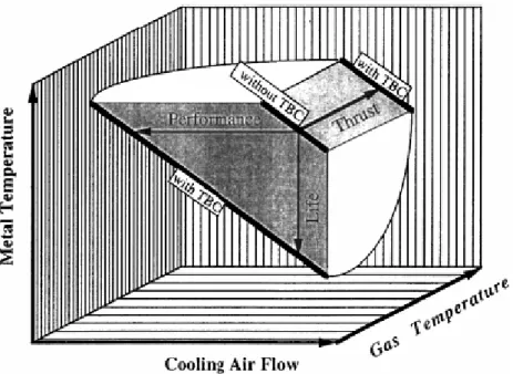
In this scene, surface engineering plays a fundamental role: the use of advanced ceramic thermal barrier coatings (TBCs) allows in fact to increase the turbine entry temperature (TET). The role of the TBC is, as their name suggests, to provide thermal insulation for the blade, allowing a high thermal gradient to be subtended across the ceramic thickness without any increase in the metal surface temperature. TBCs offer the potential either of increasing TET by between 70 and 150°C or reducing the need for blade cooling by about 36% (Strangman, 1985) (Fig. 1.5). Both these possibilities are very attractive to turbine blade designers. In the first case the application of the coating is equivalent to 2-3 generations of turbine alloy development. In the second case an improvement in efficiency of 0.25% could be realised. Although such feature may not appear significant, the subsequent saving could be of the order of 8.5 millions of euro per annum for an airline operating a fleet of 747 or 777 aircrafts (Morrell and Rickerby, 1998).
Fig. 1.5: Potential benefits in gas turbines for the use of TBCs: depending on operating conditions and requirements, TBCs can improve engine performance and thrust
as well as component lifetime (Peters, Leyens, Schulz, and Kaysser, 2001).
Nowadays TET exceed 1400°C while the mean blade temperature is around 1000°C, with peak temperatures of 1100°C which is close to 90% of the alloy’s melting point; the forecast within the next ten years aim to reach a TET of 1760°C (Kaysser et al., 1998).
1.3 Anatomy of a thermal barrier coated blade
Thermal barrier coating systems are characterized by a complex structure which consists of three layers, two ceramics and one metallic, deposited on the metal
body of the blade. Thus, proceeding from the metallic substrate to the outside, the order is (Fig. 1.6):
• bond coat
• thermally-grown oxide (TGO) • thermal barrier coating (TBC)
It has to be noted that, while the bond coat and the TBC are deliberately deposited on the metal substrate, the TGO is the result of bond coat oxidation during the TBC deposition (Jaslier and Alperine, 1998).
Fig. 1.6 Illustration of a typical coating system for a high-pressure turbine blade. In red the schematic profile of temperature is highlighted; the drop of temperature close to the blade surface is due to the presence of a thin cooling air film (Sourmail, 2003).
1.3.1 Internally-cooled Ni-based superalloy
Despite Goulette’s forecasts regarding the gas turbine materials usage (Goulette, 1995), and despite the increasing interest in ceramic matrix composites (CMCs) both for rotating and static components (Ohnabe, Masaki, Onozuka, Miyahara, and Sasa, 1999), titanium and nickel alloys continue to be the major constituents of the aero engines (Fig. 1.7).
Titanium, for its strength and density, is the ideal base material for alloys for 'low temperature' compressor blades while it is replaced by Nickel-based superalloys for the high temperature components.
As shown in Fig. 1.8 these alloys have matured over the years from wrought to cast, then to directionally solidified alloys and finally to single crystal material allowing the increase in operating temperature of turbine components (Schulz et al., 2003).
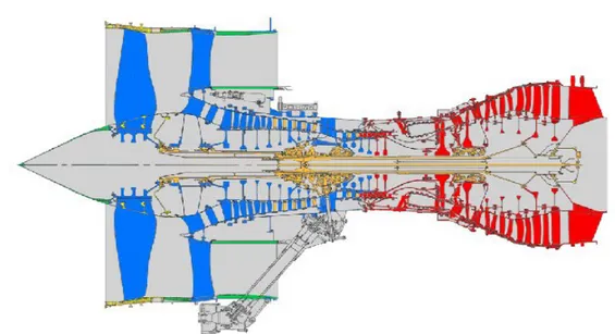
Fig. 1.7 The different materials used in a Rolls-Royce jet engine. Titanium-based superalloy (blue), Nickel-based superalloys (red), steel (orange) (Cervenka, 2000).
The first generation of Nickel-based superalloys contained concentrations of aluminium in excess of about 10 wt% or chromium in excess of 16 wt%; this is the aim to combine excellent mechanical properties at elevated temperatures with a certain oxidation/corrosion resistance. In an oxidizing atmosphere, in fact, these alloys are able to form scales, in which alumina and/or chromia predominate. Such protective scales are capable to decrease further substrate attack. When aluminium and chromium are present in combination, much lower levels of aluminium are required (typically 5 wt%) to establish a protective alumina scale (Nicholls, 2000).
Fig. 1.8: Increase in operating temperature of turbine components made possible by alloy development, manufacturing technology and TBCs (Schulz et al., 2003).
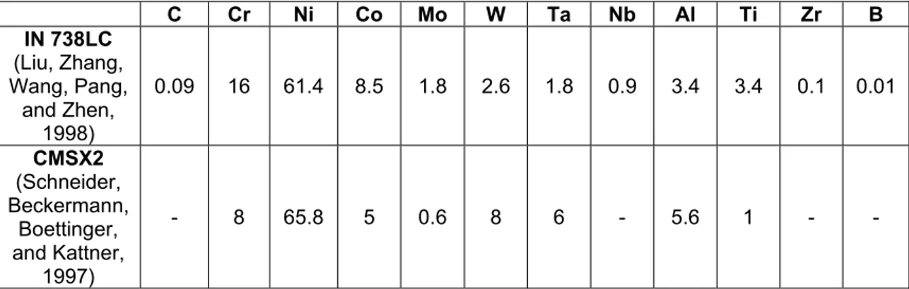
Recent generations of superalloys for single crystal turbine blades, contain as many as 5 to 12 additional elements among them relatively high percentages of refractory elements such as Ta, W or Re which enhance the high-temperature mechanical properties (Chen J.H. and Little, 1997). Unfortunately this is done at the expense of environmental resistance as the percentage of Cr and Al is dicreased. In Table 1.1 is reported the composition of two Nickel-based superalloys: a conventional casted (IN 738 LC) and a single crystal (CMSX2).
C Cr Ni Co Mo W Ta Nb Al Ti Zr B IN 738LC (Liu, Zhang, Wang, Pang, and Zhen, 1998) 0.09 16 61.4 8.5 1.8 2.6 1.8 0.9 3.4 3.4 0.1 0.01 CMSX2 (Schneider, Beckermann, Boettinger, and Kattner, 1997) - 8 65.8 5 0.6 8 6 - 5.6 1 - -
Table 1.1: The composition (wt%) of the conventional casted IN 738 LC and the single crystal CMSX2.
Given the severe environmental conditions in which the blades operate, the removal of the beneficial elements for oxidation resistance implies even greater degradation problems.
To palliate this issue, an external coating is applied to the blades. The use of coatings permit the separation (or partial separation) of surface- and substrate-related properties. Thus, coating systems are designed to provide a more optimized environmental-protection capability without the constraints of high strength that are normally placed on structural alloys for load-bearing components. The primary aim of the coating is its ability to produce a stable, slow-growing surface oxide capable of providing a barrier between the coating alloy and the environment. Thus many coatings contain Aluminum, Chromium, or Silicon (Nicholls, 2000).
1.3.2 Oxidation-resistant metallic bond coat
It is difficult to draw general rules as to which oxidation-resistant coating is used in which application. Even for a given application and a given engine, different commercial strategies may imply a different choice of coatings: opting for a higher efficiency and therefore higher temperatures at the expense of long life means that the operating conditions are changed, and the dominant degradation mechanisms may be different (Fig. 1.9).
The oxidation-resistant coating is also called bond coat (if used with a thermal barrier) because it provides a ‘transition' layer on which the ceramic top coat adheres better than on the substrate.
The numerous variants of environmental protection coatings or bond coats can be divided into two categories: diffusion and overlay coatings (Goward, 1998).
Diffusion coatings are formed by the surface enrichment of an alloy with either Aluminum (aluminides), Chromium (chromized), or Silicon (siliconized); their properties depend on the process methodology, the substrate composition and the subsequent heat treatment. Typically aluminide coatings contain in excess of 30 wt% Aluminum and are deposited to thicknesses between 30-100µm, depending on the type of aluminide formed. They can be applied to hot gas components using a range of techniques including pack cementation (Goward and Cannon, 1988), overpack chemical vapour deposition (CVD), gas phase CVD, and metallizing (Goward and Cannon, 1988). Aluminide coatings offer satisfactory performance for many aviation, industrial and marine engine applications unless they are to perform either under severe hot corrosion conditions or at temperatures above 1100°C. Improvements in oxidation/corrosion resistance are reached with modified aluminides: alloying additions include Cr, Si, Ta, Hf, Zr, the Rare Earth element (e.g. Y), and precious metals (e.g. Pt and Pd). The modified coatings are deposited by: co-deposition of elements from the pack or slurry, pre-treatment of the superalloy before pack aluminising or deposition of a metallic layer using electroplating or chemical-vapour deposition (Nicholls, 2000).
Fig. 1.9: Optimum coating composition in relation to oxidation and hot-corrosion resistance (Sourmail, 2003).
Overlay coatings represent a family of corrosion-resistant alloys specifically designed for high-temperature surface protection and are often referred to as M-Cr-Al-X coatings, where M is Ni, Co, Fe or a combination of these and X is an oxygen-active element, for example Y, Si, Ta, Hf or a precious metal, for example Pt, Pd, Ru, Re (Nicholls, 2003). The composition of the M-Cr-Al part of the system is selected to give a good balance between corrosion resistance and coating ductility, while the active element addition(s) are intended to enhance the adherence (Smeggil, Funkenbusch, and Bornstein, 1986) of the protective oxide scale under cyclic operation of the turbine and to decrease oxidation rates
(Nicholls, 2003). Overlay coatings, in a typical thickness of 125-200 µm, have been deposited by using the plasma-spray or the electron-beam physical vapour (Goward and Cannon, 1988) deposition methods (Nicholls, 2003).
1.3.3 The thermally grown oxide
The operating conditions in gas-turbine engines result in bond coat oxidation and in the formation of an interlayer, the thermally grow oxide (TGO), at the metal-ceramic interface (Stott and Wood, 1987).
The interconnected porosity that always exists in the top-coat allows easy ingress of oxygen from the engine environment to the bond coat. Moreover, even if the top-coat were fully dense, the extremely high ionic diffusivity of oxygen in the ZrO2-based ceramic top-coat (10-11 m/s at 1000°C) (Singh, Wolfe, and Singh,
2002) renders it ‘oxygen transparent’.
The oxygen diffusion plays a key role in the further growth of the TGO, in fact although in some case it is controlled by outward diffusion of Al, leading to the formation of the new TGO at the TGO/top coat interface or at the α-Al2O3 grain
boundaries within the TGO, generally it is controlled by inward diffusion of the oxygen through the TGO into the bond coat (Stott and Wood, 1987).
TGO growth has to be carefully controlled: the interfacial alumina is designed to act as an oxygen diffusion barrier that retards further bond coat oxidation. Any unwanted excessive TGO growth would cause volumetric expansion which would eventually disrupt by spallation the overlying ZrO2 layer. This means that the
ideal bond-coat is engineered to ensure that the TGO forms as highly adherent α-Al2O3 and that its growth is slow, uniform, and defect-free.
The TGO plays an important role for TBCs performance; failure in TBCs is almost always initiated at or near the TGO, mostly between TGO and bond coat. Thus, although TBC spallation cannot be simply correlated to the TGO thickness (Schulz, Menzebach, Leyens, and Yang, 2001), the control of this oxide growth should allow an increase in the life of the system. The amount of oxidation depends on the time spent at high temperatures. It has been shown that spallation occurs when the oxide at the interface reaches a critical thickness of about 4-6 µm (Toriz, Thakker, and Gupta, 1989).
Thermal-cycling tests to measure the TBC lifetime show that the growth rate of the TGO can be expressed by the equation: dn=k
p’t with d the thickness of the
TGO, t the time at temperature of test, kp’ the growth constant and n the
exponent.
In their experimental work, Schulz et al. show that TGO thickness follows nearly the same growth kinetics regardless of the substrate alloy and that the classical parabolic law with n=2 and kp’=1.5*10-17m2/s works well only for short duration
tests while a reasonable agreement with experimental data is obtained with values n=3.33 and kp’=2*10-16 m3.33/s (Schulz et al., 2001).
1.3.4 Ceramic top coat
The selection of ceramic top coat materials is restricted by some basic requirements: high melting point, no phase transformation between room temperature and the operation temperature, low thermal conductivity, chemical inertness, a thermal expansion match with the metallic substrate, good
adherence to the metallic substrate and low sintering rate of the porous microstructure (Cernuschi, Bianchi, Leoni, and Scardi, 1999).
Zirconia’s very low thermal conductivity (one and half orders of magnitude lower than that of a typical superalloy such as MAR-M 247) (Wilkes and Lagedrost, 1973), (Sink, Hoppin, and Fujii, 1979), high melting point, inertness and relatively high coefficient of thermal expansion, closely matching that of the metal substrate, make it ideal as TBC.
Unfortunately, for this application at high temperature the pure Zirconia can not be used because of its polymorphism and particularly because of its large volume expansion, about 3-5% (Bocanegra-Bernal and Diaz De La Torre, 2002), associated with the martensitic transformation tetragonal→monoclinic (t→m). The pure oxide, in fact, can exist in three crystal forms, a cubic structure stable at the highest temperatures, between the melting point (2710°C) and 2369°C (Du, Jin, and Huang, 1991), a tetragonal form stable at intermediate temperatures (2369-1114°C) (Yashima, Kakihana, and Yoshimura, 1996) and a monoclinic form stable at lower temperatures.
The disruptive t→m phase transformation can be suppressed by total stabilisation in the cubic form, in a material called Fully Stabilized Zirconia (FSZ), but the most useful mechanical properties are obtained in a multiphase material known as Partially Stabilized Zirconia (PSZ) (Garvie, Hannink, and Pascoe, 1975).
1.3.4.1 Stabilized Zirconia alloys
ZrO2 can be stabilized by the addition of certain amount of various divalent (e.g.,
Ca2+, Mg2+), trivalent (e.g., Y3+, Sc3+, Ln3+) or tetravalent (e.g. Ce4+) oxides of cubic symmetry (Kountouros and Petzow, 1993).
Early TBCs, at the beginning of 1970’s, were manufactured by plasma spray using magnesia (25 wt% MgO) or calcia (20 wt% CaO), which performed well in service at operating temperatures below c.a. 1000°C (Morrell and Rickerby, 1998). Above this temperature significant diffusion of Magnesium or Calcium ions occurs and precipitates of MgO or CaO are formed (Iwamoto, 1981) resulting in an increase in thermal conductivity and in the monoclinic content of the coating (Taylor, Brandon, and Morrell, 1992).
This limitation of low operating temperature allied to phase instability was overcome by the introduction of Zirconia partially stabilised with Yttria (Y-PSZ) in the late 1970’s.
A partially stabilized Zirconia alloy consists, in the temperature range of 1000-1500°C, in a metastable tetragonal solid solution, known commonly as t’, instead of a tetragonal+cubic assemblage, as expected from the equilibrium phase diagram. In this metastable condition, the material can be thermally cycled without undergoing the disruptive tetragonal-monoclinic transformation that compromises the mechanical integrity of the coating. Addition of 7 to 8 weight percentage (~4 to 4.5 mol%) Y2O3 stabilizes the t’ phase for extended periods at
temperature up to 1200°C, with no precipitation of Y2O3 from the solution (Taylor
et al., 1992).
Y-PSZ has a thermal conductivity (2 Wm-1K-1) (Saruhan, Francois, Fritscher, and Schulz, 2004) which is more than an order of magnitude below that of the
Ni-base superalloy. Furthermore, as a ceramic, it also shows a relatively high coefficient of thermal expansion (~11x10-6 °C-1) (Fritscher, Szucs, Schulz, Saruhan, and Peters, 2002), which comes close to that of the metal substrate (~14x10-6 °C-1), and which, for this reason, upon thermal cycling allows the accommodation of strain without immediate spallation.
To further alleviate these stresses, microstructural features such as cracks and porosity are deliberately engineered into the top coat, making it highly compliant (elastic modulus ~50 GPa) and ‘strain tolerant’ (Padture, Gell, and Jordan, 2002). Y-PSZ has a relatively low density (~6.4 Mgm-3) (Padture et al., 2002), which is important for parasitic weight consideration on rotating engine components. It also has a hardness of ~14 Gpa (Padture et al., 2002), which makes it resistant to erosion and foreign body impact. Y-PSZ is also resistant to ambient and hot corrosion. Finally, Y-PSZ has a high melting point (~2700°C) (Padture et al., 2002), making it suitable for high-temperature applications.
It is worth mentioning that additions of >20 wt.% of Yttria to Zirconia yields a full stabilized material, known as Yttria fully stabilized Zirconia (Y-FSZ). This material might be preferred since it occurs as an equilibrium single cubic phase above ~1000°C and is kinetically constrained from transforming at lower temperatures. Moreover, this composition has, at room temperature, a 30% lower thermal conductivity than the standard Y-PSZ. However, this difference is reduced to about 10% at service temperature (Azzopardi, Mévrel, Saint-Ramond, Olson, and Stiller, 2004) and durability studies revealed a cyclic life much longer for metastable t’ than for ‘stable’ cubic coatings (Stecura, 1985).
1.3.5 TBC system Damage mechanisms
Blades and vanes of high pressure sections of aero engine turbines are among the most highly loaded parts in engineering components, in fact, while working at temperatures approaching the substrate melting point, they must be strong enough to carry the centrifugal loads due to rotation at more than 10,000 rpm. They must also be resistant to fatigue and thermal shock, so that they will not fail under the influence of high frequency fluctuations induced by the gas conditions, and they must also be resistant to creep, corrosion and oxidation (Sourmail, 2003).
The most severe type of corrosion is hot corrosion which occurs in engines burning fuels containing Vanadium, Sulfur and Phosphorous. The molten sodium salts of Vanadium and Sulfur oxides condense onto the TBC in the 600–1000°C temperature range (Luthra and Spacil, 1982) and dissolve the protective surface oxides. Due to the different morphologies observed, the hot corrosion phenomena are classified into: high-temperature hot corrosion (type I, 800-950°C), low-temperature hot corrosion (type II, 600-800°C) and vanadic
corrosion (535-950°C) (Goward, 1986).
Another problem may also arise from the fact that the oxidation-resistant coatings are not in thermodynamic equilibrium with their substrate, hence they tend to diffuse within it. This is of concern, not only because the loss of scale-forming elements to the surface reduces the oxidation life of the coating, but also because it results in the formation of embrittled phases below the coating that
modify the carefully designed mechanical properties of the substrate (Nicholls, 2000).
Another TBC degradation mechanism is known as Foreign Object Damage (FOD), whereby airborne material (dirt, sand, ash, etc.) ingested by the engine, or produced within the engine (from combustion chamber walls, for example), impacts the TBC surface. In rotating components, such as turbine blades, the impacts can have quite high velocities and may cause extensive damage to the ceramic top coat. Repeated exposure to even small particles can cause erosion of the TBC surface. Premature failure of the TBC can cause decreased engine performance or even engine failure (Kernan, He, and Heuer, 2003), (Nicholls, Deakin, and Rickerby, 1999).
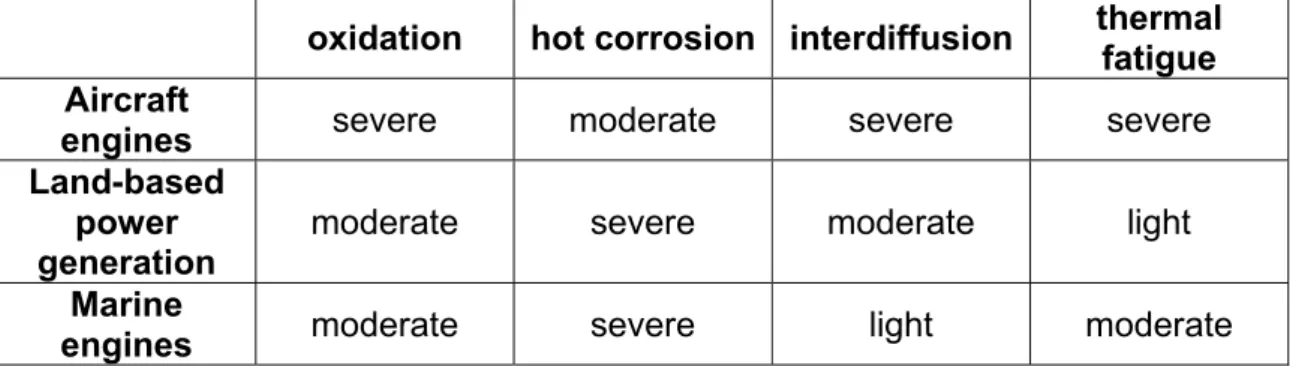
Table 1.2 compares the severity of the different surface-related problems for gas turbine applications; different service conditions result, in fact, in different degradation mechanisms being predominant.
oxidation hot corrosion interdiffusion thermal fatigue Aircraft
engines severe moderate severe severe Land-based
power
generation moderate severe moderate light Marine
engines moderate severe light moderate
Table 1.2: Comparison of problems for gas turbine applications (Pettit and Goward, 1983).
With today's jet engine operating temperatures thermal barrier coating failure results in melting of the blade. As a consequence, failure of the coating can be catastrophic and very costly. The price of a single blade can easily reach € 7500, replacing a row can cost 1.5-2.2 millions of euro and if a blade breaks off during operation and causes further damage downstream, the cost can be in the tens millions of euro (Phosphorus light way to longer life, 2003).
Part 1:
Competing technologies for TBC deposition
Thermal barrier coatings can be manufactured by different processes, such as Electron Beam Physical Vapour Deposition (EB-PVD) or Air Plasma Spray (APS). Different techniques result in significantly different microstructures. Although more costly than APS, EB-PVD is the preferred method for high-pressure turbine blades, where a good surface finish is paramount and excellent strain compliance and adhesion are required.
1.4 Basic principle of Plasma Spray
The plasma spray process belongs to the more general category of thermal spraying methods. The invention of which dates back to 1909 when Dr. Max U. Schoop developed a crude wire metallizing gun using oxygen and acetylene as the heat source and compressing air to atomize and project the molten metal (Sulzer, 2004).
The basic principles of this technique remain fundamentally unchanged; the modern thermal spray deposition, in fact, consists of melting a consumable (most often powder or wire) and projecting it as molten particles onto the substrate (Fig. 1.10).
The modern plasma spraying process uses a direct current (DC) electric arc to generate a stream of high temperature ionized plasma gas, which acts as the spraying heat source. The coating material, in powder form, is carried in an inert gas stream into the plasma jet where it is heated and propelled with a particle rate of 200-300 m/s (Halldearn, 2000) towards the substrate; because of the high temperature, that can exceed 16,000°C (efunda engineering fundamentals, 2005), and of the high thermal energy of the plasma jet, with this technique even materials with high melting points can be sprayed.
Upon impact with the substrate, the molten particle flatten, forming splats, and solidify very rapidly (the quench rate approaches 106 K/s); this, together with the thermal strain due to the expansion coefficient mismatch with the substrate, leads to microcraking through the splats and inter-splat cracking (Lawson, Nicholls, and Rickerby, September 1997) (Fig. 1.11). Furthermore, due to the way in which the coating builds up, a sprayed coating typically includes voids: namely for a deposition rates of 1-5 kg/h the porosity is 5-10% (Halldearn, 2000). The presence of air in the atmosphere surrounding the process leads to cooling and a slowing of the spray stream and also to the inclusion of oxide particles in the sprayed coating (if metallic). During the process, in fact, some air enters in the spray stream and oxidizes the sprayed material. In order to reduce these drawbacks, a couple of variants of the conventional plasma spraying have been introduced: the Low Pressure Plasma Spraying (LPPS) and the Vacuum Plasma Spray (VPS). They are identical to plasma spraying except for being done in inert gas at low pressure and in vacuum respectively (Sourmail, 2003), (Strangman, 1985), (Soechting, 1998).
Fig. 1.11 A plasma-sprayed TBC (Nicholls, Lawson, Johnstone, and Rickerby, 2002).
1.5
The basic principle of Electron Beam Physical
Vapour Deposition (EB-PVD)
The application of evaporation and deposition on a substrate for the production under vacuum of thin (under 1 µm thick) metal films began at the end of the last century. The 1930s saw the first applications of Electron-Beam (EB) heating for material evaporation under vacuum but only in the middle of the 1960s, with the start of researches on thicker films (1-2 mm), was the high-power EB guns used as the basis to develop equipment for high-speed evaporation of substances under vacuum. During the 1980s a new class of protective coating for gas turbine, known as the EB-PVD TBC, was developed (Movchan, 1996).
In the deposition chamber, the electron beam hits the surface of a sintered Y-PSZ ingot to generate a melt pool under vacuum as illustrated in Fig. 1.12. The flux of vapour from the pool impinges upon substrates rotating above the melt. During evaporation the ingot is bottom-fed into the crucibles to ensure continuous growth of the ceramic coating. Oxygen is also bled into the Y2O3-stabilized ZrO2
vapour cloud to minimize any deviations from stoichiometry during coating. This process feature is required since ZrO2 becomes somewhat oxygen deficient as a
result of partial dissociation during evaporation in a vacuum. Vapour from this cloud condenses onto the turbine airfoil to form the coating (Strangman, 1985). The substrates are pre-heated prior to deposition of a ceramic layer that is typically between 125 and 250 µm thick.
Fig. 1.12 A simple EB-PVD process, the whole assembly would be under vacuum. Rotation of the electron beam is obtained by a magnetic field perpendicular to the drawing (Sourmail, 2003).
TBCs produced by EB-PVD show a microstructure characterized by a thin region of polycrystalline Y-PSZ with equiaxed grains (size ≤50 nm) (Kernan et al., 2003) at and near the metal/ceramic interface, and by columnar Y-PSZ grains (5-10 µm diameter at the column tops) (Kernan et al., 2003) growing out of the equiaxed-grain region to the top coat surface (Schulz and Schmucker, 2000) (Fig. 1.13).
The TBC’s microstructural properties are strongly affected by a hierarchy of pores introduced during the deposition process (Fig. 1.14). The first scale of porosity consists of the intercolumnar gaps (~125 nm) (Kernan et al., 2003), normal to the metal/ceramic interface, separating the columnar grains. The primary columns exhibit a feather structure, involving two additional scales of porosity. One of these is the segmentation that defines the ‘branches’ of the feather, which can be envisaged as microcolumns inclined at ~50° to the horizontal axis.
Fig. 1.13: ESEM image of an EB-PVD TBC.
This type of porosity (5-20 nm across) (Kernan et al., 2003) extends inward to about 1/3 to 1/2 the columns radius and systematically evolves into discrete pores of high aspect ratio still aligned on planes inclined at ~50°. The second scale of porosity consists in random distributed nanoscale spherical pores (~20 nm wide) more evident near the core of the columns (Lu, Levi, Wadley, and Evans A.G., 2001)
It has to be noted that variations in deposition process parameters modify the growth morphologies and kinetics of the Zirconia columns and produce microstructures with different degrees of packing and of interaction between columns. Thus, much research has been directed at investigating the relationship between the microstructure of the EB-PVD TBC layers and the various processing parameters such as: deposition rate, pressure in the coating chamber or bond coat surface texture. In particular, rotation rate (Rigney et al., 1995), substrate temperature during processing and vapour incidence angle (Kaysser et al., 1998) seem to have a particularly significant effect.
Substrate temperature and rotational speed are process parameters that, within certain limits, affect the same microstructural TBC features (Fig. 1.15). At low temperature and low rotational speed columns often vary in diameter from root to top or from one column to the other. Columns at the root section are much thinner than at the top and they are enlarging discontinuously from root to top conically. Increasing both temperature and rotational speed improves the regularity and parallelism of the microstructure and enlarge the column diameter; this microstructure results in coatings with higher density and of higher hardness than the previous one (Kaysser et al., 1998).
Fig. 1.15: Schematic representation of the influence of rotational speed and absolute substrate temperature (expressed as a fraction of Zirconia melting point: Tm) on
columnar microstructure evolution of EB-PVD TBCs (Kaysser et al., 1998).
The microstructure can also be varied by changing the rotational speed whilst keeping the deposition temperature constant: in fact a speed reduction facilitates the formation of the so called bended or c-shaped structure in the columns. Such feature can be clearly observed (by scanning electron microscopy) cross sectioning a TBC perpendicularly to the rotation axis (Fig. 1.16).
Fig. 1.16 SEM of the structure of Zirconia columns taken in cross-section in the plane perpendicular to the axis of rotation (Rigney et al., 1995).
In fact the c-shaped structure is due to the continuous change, during each revolution, both of the vapour impact angle and of the amount of vapour particles that adhere on the sample surface. These variations would be less evident at higher rotational speed. In a c-shaped coating the curved section is periodic through the thickness of the deposited material with a period equal to one revolution of the substrate in the coater.
On the other hand, sectioning the same sample along the direction parallel to the rotation axis, only a little curvature in the grains of the columns would be observed. This is due to the fact that, in this direction, the variation in the angle between the substrate surface and the centre of the melt pool during rotation is much smaller than in the previous case (Johnson, Ruud, Bruce, and Wortman, 1998) (Fig. 1.17).
1.6 Comparison between APS and EB-PVD
Both plasma sprayed and EB-PVD deposited Y-PSZ TBCs yield metastable tetragonal single-phase supersaturated with Yttria and commonly known as t’. This phase is typically obtained from quenching the cubic phase of bulk ZrO2-7wt%Y2O3 (7YSZ) ceramics (see Chapter 2).
In plasma sprayed TBC the t’ feature results from a solid-state transformation; the sprayed TBC, in fact, evolve from the melt as cubic and transform to t’ upon cooling (Lelait and Alperine, 1991).
In EB-PVD deposits t’ forms directly from the vapour, due to the randomly condensation of Yttrium and Zirconium oxide molecules at the relative temperature T/Tm of about 0.4 (where T and Tm are the absolutely surface temperature and melting point of Zirconia respectively). In this temperature regime, cation diffusion is too sluggish to allow for the Yttrium to rearrange in an Yttrium rich cubic phase and a low Yttrium content trasformable tetragonal phase results (Jaslier and Alperine, 1998).
1.6.1 Surface finish
For aerofoil applications, the coefficient of friction (Cf) of the blade surface is
directly related to roughness and, as a consequence, the Cf value influences the
heat transfer coefficient and the efficiency of the turbine (Watt, Allen, Bains, Simons, and George, 1997).
Fig. 1.18: Primary loss coefficient in function of Reynolds number for a high pressure turbine aerofoil (Morrell and Rickerby, 1998).
As shown in Fig. 1.18 for Reynolds number values between 0.5-1.5x10⁶ (which covers the range for high-pressure turbine aerofoil) the TBCs obtained by plasma spraying significantly affect the turbine aerodynamic performance.
The plasma sprayed TBC has a typical surface roughness of c.a. 10 µm Ra and a peak to valley height of 80-100 µm which results in an increase in the primary loss coefficient in the turbine from 1.5% to 3.5% (Watt et al., 1997).
Consequently, airfoils with thermally sprayed TBC required polishing to bring the surface finish to values of 2-3 µm, however erosion of the coating in service would increase the surface roughness of the TBC back to values approaching 10 µm (Morrell and Rickerby, 1998) (see section 1.6.3).
In contrast the EB-PVD TBS surface finish is close to that of the metal surface, typically 1.0 µm Ra with a peak to valley height of 10 µm. These coatings exhibit a primary loss coefficient of the order of 1.5%, and do not appear to increase the loss coefficient over that observed for the uncoated metal surface.
1.6.2 In-plane Young’modulus
The in-plane Young’s modulus of TBC systems can be measured by various techniques: compressive and tensile tests, dynamic vibration and ultrasonic velocity measurements tests, and the values generated significantly vary depending on the adopted techniques. Calculation of modulus based on the measurement of a compression surface and shear elastic waves in the coating material are reported in Fig. 1.19 (Morrell and Rickerby, 1998), Taylor et al., 1992).
Fig. 1.19: Young’s moduli of solid sintered 8YSZ, plasma sprayed and EB-PVD 8YSZ measured by dynamic techniques (Morrell and Rickerby, 1998).
The modulus of the plasma spray TBC system is similar to that of the sintered material, with a room temperature value of 200 GPa reducing to 160 GPa at 1000°C. The EB-PVD TBC, in comparison, exhibits a Young’s modulus approximately half of that of the bulk material, ranging from 100 GPa at room temperature down to 40 GPa at 1000°C (Morrell and Rickerby, 1998). The relatively high modulus associated with the plasma spray TBC leads, during engine operations, to more significant cracking damage in the coating than for the EB-PVD TBCs case, especially in the blade area with tight radii of curvature 1.6.2.1 Relation between microstructure and mechanical properties
EB-PVD TBCs are more durable than sprayed TBCs because of their unique columnar structure that gives the coating high strain compliance. The disconnected columns, in fact, can separate at high temperatures, accommodating thermal expansion mismatch stresses (Strangman, 1985). It has
to be noted, however, than better mechanical properties can be reached by process parameter optimization.
EB-PVD microstructures (see section 1.5) with tightly packed Zirconia columns, and thus with less void space between columns, will be stiffer and have correspondingly higher modulus in comparison to ‘looser’ structures. In the limit, for columns packed so tightly together that the space between them approaches the thickness of a grain boundary, the modulus will approach that of bulk Y-PSZ. Microstructures with widely spaced columns that are independent of each other will be very compliant and have low modulus. In the limit, for columns that are spaced widely enough that they do not contact each other at any time, the stiffness of the system is dominated by the substrate and very little extra stiffness is afforded by the TBC (Johnson et al., 1998).
For the same specimen, the anisotropy microstructure, due to rotation rate during deposition (Rigney et al., 1995), gives rise to two different values of in-plane Young’s modulus with difference that can exceed 30 GPa; in particular it is lower if measured in a perpendicular direction to the rotation axis during the deposition than in parallel direction (Johnson et al., 1998).
The elastic modulus values, measured using the resonant frequency of flexural vibrations, cover the range between 10 and 77 GPa.
The residual stress is also dependent on the TBCs microstructure and is therefore correlated with the in-plane coating elastic modulus. The residual stress is generated during the coating deposition and it is caused by the strain due to thermal expansion mismatch between the coating and the substrate upon cooling from the deposition temperature to room temperature. For the same thermal mismatch strain, EB-PVD microstructures with tightly packed columns and high modulus will have higher compressive residual stresses than microstructures with well-spaced columns and low modulus. Stress levels between -70 MPa compressive and 20 MPa tensile have been observed (Johnson et al., 1998). Residual stress is shown to affect the strain tolerance of an EB-PVD TBCs. The compressive shear test, applied to characterize the strain tolerance, reveal, in fact, that higher levels of residual stress result in lower applied strains for failure. The test measures the strain at failure for a TBC that delaminates from an edge-initiated crack from a substrate that is loaded in compression. The compressive shear failure strain is sensitive to both the adhesion of the coating to the substrate and the residual stress. The TBC fails in the compressive shear test when the strain near the free edge exceeds the strain to delaminate the coating from the substrate. The strain state in the coating is the sum of the strain on the substrate, which is transferred by shear strain to the coating, and the initial strain state of the coating. For coatings with similar interfacial strengths, it is expected that a coating with a higher compressive residual stress requires less applied compressive strain before failure. As a result EB-PVD TBCs with lower residual stress are more strain tolerant than those with higher stresses (Johnson et al., 1998).
1.6.3 Erosion resistance
Erosion of TBC has received increasing attention since the TBC were applied on turbine blades and nozzle guide vanes: these components, in fact, do experience
particle impacts under the most exacting conditions in terms of temperature, particle velocities and impingement angle. The previous applications on the combustor parts, instead, do not suffer from significant erosion as the gas flows parallel to the coating surface.
An erosion test program run at the temperature of 540°C (Toriz, Thakker, and Gupta, ) indicated that at low angles of attack Y-PSZ EB-PVD TBC is only 2 times more erosion resistant than APS Y-PSZ. The benefit, however, increases with impingement angle, so that coatings applied to flow path airfoils, where the attack angle approaches 90°, will see life improvements of up to 1000%: in this conditions, in fact, EB PVD Y-PSZ is 10 times more erosion resistant than the standard APS Y-PSZ.
Further erosion studies, using high temperature erosion facilities, confirm these results both at room temperature and 910 °C (Nicholls et al., 1999).
This improved erosion behaviour is associated with the modes of failure for the APS and EB-PVD ceramic coatings. The APS coating fails by propagation of cracks around splat boundaries and through the microcrack network. In contrast, the erosion of EB-PVD TBC requires the generation, across individual columns, of new crack surfaces, which are formed both near the surface and more in depth depending on impact angle. In any case, material is only lost from the near-surface region when a precracked coating is further impacted, due to the constraint offered by neighbouring columnar grains which resists pluck-out of the material (Nicholls et al., 1999). In addition to the observed low erosion rate, a further benefit of the limiting the damage in the EB-PVD coating to the near surface region is that erosion does not adversely affect the surface finish of the coating, whereas in the plasma sprayed TBC it causes the surface finish to revert quite quickly to the as deposited values, even if the coating had previously been polished (Morrell and Rickerby, 1998).
Wellman et al. investigated the effects of TBC column diameter and column inclination angle on the erosion rates of TBCs. Their experimental work shows that, all other properties being equal, specifically: density, hardness, elastic modulus and fracture toughness, the EB-PVD TBC with the smaller column diameter have a lower erosion rate. This is due to the fact that less material will be lost per cracked column if they are smaller, thus to lose a similar amount of material per impact, cracks will need to be initiated in more columns.Moreover, it has been demonstrated that if the columns are grown at an angle to the substrate, keeping the particle stream at 90° to the substrate, the erosion rate increases significantly as the inclination angle between the columns and the substrate decreases: at inclination angles less than 50° the erosion rate is greater than that of plasma sprayed coatings. This increase in the erosion rate has been attributed to the fact that under impact conditions the cracks initiate deeper in the coating than in the ‘classical’ erosion damage thus resulting in a greater loss per impact (Wellman, Deakin M.J., and Nicholls, 2005).
1.6.4 Coating adhesion
Although several methods (Chalker, Bull, and Rickerby, 1991) can be used to assess the adhesive strength of the coating, for thermally sprayed TBCs the pull-off test is widely adopted. For a 250 µm thick as-deposited plasma sprayed
TBC the adhesion strength is in the range of 20-40 MPa with the strength decreasing as the coating thickness increases (Morrell and Rickerby, 1998). The pull-off tests does not generate useful data for EB-PVD TBC systems, because in this case the bond strength is over the maximum strength the glue used in the test can tolerate (typically 50-80 MPa). The transverse scratch adhesion test has been used instead and the value of interfacial strength obtained for an as-deposited coating is 400 Mpa (Johnstone, Rickerby, and Morrell, September 1997).
Strictly linked to the adhesion is the better oxidation resistance of EB-PVD TBCs in comparison to plasma sprayed coatings. While in the case of EB-PVD TBCs adhesion to the metal substrate depends on the chemical bond, the plasma-sprayed TBCs adhesion is primarily mechanical thus in these systems a rough ceramic-metal interface is required. Such a very rough interface significantly increases the surface area that requires protection, compared to the smooth interface of EB-PVD coatings, and thus it depletes the aluminium reservoir in the bond coat more quickly (Strangman, 1985). Furthermore the undulating nature of the metal-ceramic interface produces out-of-plane stresses responsible for in service failure of APS TBC systems (Evans, Mumm, Hutchinson, Meier, and Pettit, 2001).
1.6.5 Thermal conductivity
The unique columnar microstructure that gives the EB-PVD TBC system its high strain compliance and good erosion resistance, unfortunately, leads to a relatively high thermal conductivity (1.5–1.9 W/mK) when compared to thermal sprayed coatings (0.8–1.2 W/mK) (Nicholls et al., 2002) (Fig. 1.20).
Fig. 1.20 Thermal conductivity of Y-PSZ derived from thermal diffusivity measurements by use of laser flash technique: comparison between sintered, air plasma
sprayed (APS), and EB-PVD TBCs (Peters et al., 2001).
In the plasma sprayed TBC, the microcraks, in particular those parallel to the coating substrate interface, and dispersed spheroidal micro-porosity act as air gaps offering a significant resistance to the heat flow. In contrast, in the EB-PVD
TBCs, the column boundaries lay parallel to the principal heat flux direction and have little effect on the conductivity; thus, in these systems, only the intra-columnar fine porosity (see section 1.5), accounts for the reduced thermal conductivity over that of the bulk ceramic (Nicholls, Lawson, Rickerby, and Morrell, 1998).
Furthermore, whilst the thermal conductivity of the thermally sprayed TBC is essentially insensitive to coating thickness, this is not the case for EB-PVD ceramics. The nucleation and competitive growth typical of the PVD process lead to the elimination from the structure of those grains with ‘less favoured’ growth directions. The decrease in the number of oblique columnar boundaries in the outer part of the coating is responsible for the increase in thermal conductivity in this area; less boundaries mean, in fact, less additional centres capable of scattering thermal waves (Nicholls et al., 1998).
To summarize what has been stated so far, the plasma spray process has proved inadequate for deposition of ceramic coatings onto HPT aerofoils due to: the poor coating surface finish, the low strain compliance, the high erosion rate and, the retention and cooling hole obstruction problems (Rigney et al., 1995). Indeed in jet engine operating conditions, the lifetime of TBC coatings obtained by EB-PVD is reported to be between 8 and 13 times longer than equivalent system where the TBC is deposited by plasma spray (Schulz, et al. 2003).
In Table 1.3 a direct comparison between the properties of plasma sprayed and EB-PVD deposited TBC is made.
Table 1.3: Properties of 8YSZ coatings produced by EB-PVD and plasma sprayed processes (Singh et al., 2002).
Part 2:
Operations at high temperature
The EB-PVD TBCs key properties are seriously affected by changes over time with high temperature exposure. When the surface temperature of TBCs approaches 1200°C in long-term operations, in fact, phase transformation and sintering takes place. The Y-PSZ phase transformation allows changing of t’ phase into the equilibrium tetragonal (t) and cubic (c) phases. During cooling, the t phase in turn transforms into the monoclinic (m) phase which results in coating disintegration, especially for large amount of transformed t’ phase (see Chapter 2).
Sintering, in the field of EB-PVD TBC, is connected to a reduction of the open porosity, which can reach 20 vol% in the as-deposited coating. Such densification leads to a general worsening both of thermal and mechanical properties. In fact, after ageing, an increase in thermal conductivity is always observed. This leads to an enhancement both of creep and bond coat oxidation. Indentation tests carried out by Kernan et al. on Y-PSZ EB-PVD TBCs reveal an increase of ~25 % in hardness in coating aged for 4 h at 1204°C, in comparison to the as-deposited one. The same analysis also demonstrates a decrease in high temperature damage tolerance: the cracks on the corner of the indents shifted from a value below 10 µm (of the pristine coating) to 30 µm in the aged sample (Kernan et al., 2003).
Erosion tests conducted at room temperature by Wellman et al. on two sets of Y-PSZ EB-PVD TBCs aged at 1100°C (for 100h) and at 1500°C (for 24h), show in both cases an increase of the erosion rate if compared to the as-deposited samples and in particular an increase by a factor 2 in the sample aged at 1100°C and by a factor 4 in the sample aged at 1500°C (Wellman and Nicholls, 2004). Fritscher et al. have shown that sintering also leads to a dramatic increase in elastic modulus up to a factor 4 after ageing at 1100°C for 24h (Fritscher et al., 2002).
These changes in microstructure, as well as in mechanical properties, result in higher thermally induced stresses and in a decrease in thermal-fatigue lifetime of the coating (Goedjen, Brindley, and Miller, 1995).
The demand for enhanced long-term reliability at even more elevated operating temperature leads to researching of new material and process for TBCs (Levi, 2004). The various approaches found in the literature to overcome these problems can be divided in two main groups: the experimentation of alternative oxide materials and the improvement of the properties of the state-of-the-art Y-PSZ.
The first approach could yield huge amount of three and more components oxides. Clarke, on the basis of existing models for the minimum thermal conductivity of insulating materials, proposed a materials selection guideline. He identified possible alternatives to Y-PSZ as candidates with a large molecular weight, a complex crystal structure, a non-directional bonding and a large number of different atoms per molecule (Clarke, 2003). These parameters are
well embodied by a promising class of compounds: AxByOz where A is a Rare
Earth element (typically a Rare Earth such as La, Gd, Nd, etc.) and B is Zr, Hf or Ti (Saruhan et al., 2004), (Vassen, Cao, Tietz, Basu, and Stover, 2000).
The research at Cranfield University can be placed in the second group because the reluctant behaviour of the industries against the introduction of totally new materials and also because Y-PSZ has several important characteristics that will make it difficult to displace. Among these it is worth to remind that:
• It can be deposited by electron beam evaporation since the vapour pressures of ZrO2 and Y2O3 are comparable
• Its composition appears to have unusually good erosion resistance compared with other ceramics
• It is thermodynamically stable in contact with alumina and thermochemical compatibility with the underlying alumina is a primary requirement for any emerging top coat material, since any reaction that consumes the TGO would likely replace it with a less protective oxide (Levi, 2004).
To date, one of the most promising techniques to improve the performance of Y-PSZ seems to be the addition of Rare Earth oxides (REO).
1.7 Rare Earth oxides co-doped Zirconia
The so called co-doped materials are based on one or more REO additions to Y-PSZ. Such addition(s), while does not modify either the ceramic crystal structure (see Chapter 2) or the EB-PVD TBC columnar microstructure, offers potential benefits in reducing the thermal conductivity below current levels, by reducing the diffusional processes. In addition such co-doping could permit the manufacture of self sensing TBCs, permitting the measurement of the temperature of the ceramic using laser-induced fluorescence.
1.7.1 Reduction in thermal conductivity and diffusion coefficient
Since Zirconia and its alloys are electronic insulators, the heat transfer does not occur though electrons, as in other in crystalline solids, but only by lattice vibrations (through phonons) and by radiation (through photons).
From the expression of the total theoretical thermal conductivity of Zirconia based systems, Nicholls et al. deduced that to engineer a lower thermal conductivity in Zirconia-based ceramics, the only options are to lower the mean free paths of the heat carriers, to lower the velocity of the heat carriers, or to lower the density of the material. In real crystal structures, scattering of phonons, which can be quantified through its influence on the phonon mean free path, occurs when they interact with lattice imperfections. Such imperfections include vacancies, dislocations, grain boundaries, atoms of different masses and other phonons. Ions and atoms of differing ionic radius may also scatter phonons by locally distorting the bond length and thus introducing elastic strain fields into the lattice.
Concentrating on the role of high mass additions, research in Cranfield examined the influence of different percentages of four Lanthanide oxides (Erbia, Gadolinia, Neodymia, Ytterbia) on the thermal conductivity of EB-PVD TBCs.
Such dopant additions, both as ternary and quaternary additions, introduce vacancies as well as strain centres into the lattice; moreover, they change the colour of the TBC material increasing the coating opaqueness to infra-red radiation. They do, at the same time, reduce the phonon transport and the radiative transport mechanism in the material. The best results were obtained with Gadolinia added in a percentage of 4 mol% to Zirconia-4.5 mole% Yttria: the thermal conductivity of this system with a value of 0.88 W/mK allows an EB-PVD system to have a thermal conductivity comparable to a plasma sprayed TBC (Nicholls et al., 2002). The mismatch between the host and the additive large radius cation leads to a lower diffusion coefficient as well. Researches on the effects of addition, in percentage from 1 mole% to 5 mole%, of Praseodimia, Neodymia, Erbia and Lanthana on density of Zirconia-4.5 mole% Yttria were carried out by Matsumoto et al.; experimental work conducted on compacted powder sintered at 1300°C for 10h shows that dopants addition reduces the density in comparison to Y-PSZ sample. This means that the addition of co-dopants has an active role in reducing densification due to sintering in Y-PSZ. Such tendency to suppressing sintering and all its effects increases as the ionic radius of the doping cation increases. These results (at low addition levels) suggest that the additives alter the diffusion coefficient of the surface, grain boundary and lattice diffusional processes through the formation of a solid solution (Matsumoto, Yamaguchi, and Matsubara, 2004).
1.7.2 Gadolinia partially stabilized Zirconia
Due to the good results obtained by co-doping Y-PSZ with Gadolinia, some work has been undertaken to investigate the properties of Zirconia partially stabilized only with Gadolinia (Gd-PSZ).
Wu et al. conducted investigations to evaluate the high temperature chemical stability of ZrO2-GdO1.5 thermal barrier ceramics in contact with α-Al2O3.The tests
were conducted with the materials in powder form in order to maximize the interface area, simulating, in this way, more severe reaction condition in comparison to the planar interface existing between the real life top-coat and the α-Al2O3 TGO, were possible. The results show that there is no evidence of
Gadolinium aluminate (GdAlO3) in blends made of 50 wt% of ZrO2-7.5 mol%
Gd2O3 and 50 wt% of α-Al2O3 after a heat treatment at 1600°C for 16h. This
indicates the lack of a chemical reaction and it means that TBC top-coats with more than 7.5 mol% of Gd2O3 may not react with the TGO in-service, due to the
conservative nature of the experimental testing conditions (Wu, Padture, and Gell, 2004).
Research conducted to investigate the Gd-PSZ phase stability highlighted that Gadolinium does act as a stabilizer, yielding t’ with XRD spectra comparable to the Y-PSZ materials at 1200°C. However, partitioning and subsequent monoclinic formation occurs at substantially lower temperatures, with difference that can reach 150°C in the Gd-stabilized materials making Gadolinia a less effective stabilizer than Yttria (Rebollo, Fabrichnaya, and Levi, 2003).
1.7.3 Temperature monitoring
The TBC lifetime depends on the temperature at the bond coat-ceramic interface (Miller and Lowell, 1982) and indirectly on the heat flow into the material. Hence, accurate measurements of temperature and heat flow under operating conditions are the base for developing novel cooling schemes and predicting coating and component lifetime. Besides, the control of material temperature is fundamental since an increase of even 10-15°C in metal peak temperature halves the blade creep life (Padture et al., 2002).
In order to measure the surface temperature different systems may be used such as thermocouples, infrared pyrometry and thermographic phosphors. However, only the latter allows to overcome several of the drawbacks linked to the two first techniques. The thermocouples in fact, are intrusive and difficult to use on rotating component such as turbine blades, moreover they can detect the temperature only in the preinstalled position that cannot easily be changed. Such problem does not occur in case where pyrometry is adopted because this is an optical technique. Nevertheless its application is still problematic due to stray light (from flames), contaminated observation windows and variations in surface emissivity during operation. Equally, pyrometry only measures the ceramic surface, or near surface temperatures. The thermographic phosphor technique uses laser-induced luminescence from ceramic phosphors for measurement of the temperature. Phosphors are materials capable of emitting radiation when subject to ultraviolet radiation, X-ray, electron bombardment, friction or some other form of excitation. This emission is known as luminescence (Blasse, 1979). This technique can be adopted successfully for temperature monitoring of a ceramic host doped with Lanthanide ions because these act as luminescence centres when illuminated with ultraviolet light. The emission properties of these materials are temperature sensitive and can be used to measure point temperatures and surface temperature distributions (Feist, Heyes, and Nicholls, 2001), Feist and Heyes, 2000).