ALMA MATER STUDIORUM – UNIVERSIT `
A DI BOLOGNA
CAMPUS DI CESENA
SCUOLA DI INGEGNERIA E ARCHITETTURA
CORSO DI LAUREA MAGISTRALE IN INGEGNERIA INFORMATICA
SVILUPPO DI ALGORITMI DI
AUTOLOCALIZZAZIONE SU DISPOSITIVI MOBILI
Tesi in
ELABORAZIONE DELLE IMMAGINI LM
Relatore:
Chiar.mo Prof. Alessandro Bevilacqua
Correlatori:
Prof. Alessandro Ricci Dr. Alessandro Gherardi
Presentata da: Ettore Esposito
Sessione I
Alla mia Famiglia
ABSTRACT
Negli ultimi anni, complice la rapida evoluzione degli elaboratori e dei sensori, spinta dal mercato smartphone, una tecnologia si sta sviluppando e si sta diffondendo rapidamente. Si tratta di quella relativa agli unmanned vehicles (UV), i veicoli senza pilota, spesso nel linguaggio comune chiamati “droni”. Questi particolari veicoli sono dotati della tecnologia adatta per svolgere in relativa autonomia particolari mansioni, senza la necessità della presenza di un pilota a bordo. In questa Tesi magistrale si descrivono breve-mente le diverse categorie di UV e l’attuale livello di autonomia raggiunta nello svolgimento di alcune funzioni, grazie a tecnologie quali i linguaggi ad agenti, di cui si presentano anche alcune significative applicazioni allo stato dell’arte. Per rendere più efficaci eventuali nuove funzionalità, fornendo una metodologia di sviluppo, atta ad aumentare il grado di astrazione, viene pro-posto un approccio architetturale a tre livelli. In particolare, viene appro-fondito il secondo livello, presentando l’implementazione di una funzionalità, l’autolocalizzazione spaziale, utile ad un sistema di terzo livello per arric-chire la propria conoscenza dell’ambiente, al fine di raggiungere la massima autonomia nel controllo del mezzo. Questa prima esperienza ha consentito di approfondire le necessità in termini di hardware e software, al fine di poter effettuare una scelta mirata per l’ottimizzazione dei risultati ed un eventuale porting onboard, nella prospettiva di svincolare il mezzo da eventuali collega-menti con una stazione di terra, fino ad ora necessaria per eseguire le attività più complesse. Un interessante caso di studio consente di verificare la bontà del modello proposto e i risultati raggiunti nell’autolocalizzazione. In con-clusione, si propongono ulteriori sviluppi che potranno fornire gli strumenti necessari alla massima espressione del potenziale che gli UV possiedono.
RINGRAZIAMENTI
Vorrei ringraziare tutte le persone che mi hanno permesso di realizzare questa Tesi di laurea magistrale, cominciando con colui che ha aiutato a tirar fuori da un insieme di componenti sconnesse una piattaforma di lavoro funzio-nante, il Dr. Matteo Turci del Flight Mechanics Laboratory dell’Università di Ingegneria Aerospaziale di Forlì. Ringrazio anche tutti gli altri membri del laboratorio che mi hanno dato l’opportunità di lavorare presso la loro sede, permettendomi di imparare molto anche su argomenti fino ad allora per me sconosciuti.
Ringrazio il Professor Alessandro Bevilacqua, il Dr. Alessandro Gherardi e il Professor Alessandro Ricci per avermi dato l’opportunità di svolgere un’attività in uno dei settori a cui sono più interessato, mettendomi a dis-posizione materiale, conoscenza e soprattutto offrendomi sempre del tempo prezioso per consultarsi e guidare il lavoro.
Ringrazio i miei amici per non aver denunciato la mia scomparsa durante questi mesi, ma che al contrario mi hanno aiutato, portandomi con la forza lontano dal monitor del mio computer a bere una birra fresca quando era proprio ora di staccare la spina.
Ed infine un caloroso ringraziamento alla mia famiglia che mi ha suppor-tato, e sopporsuppor-tato, durante questi anni di università compresi gli ultimi mesi dello svolgimento di questa Tesi.
Contents
1 Introduzione 1
2 I veicoli autonomi 3
2.1 Unmanned Ground Vehicle - UGV . . . 4
2.2 Unmanned Surface/Undersea Vehicle - USV/UUV . . . 7
2.3 Unmanned Space Vehicle - USV . . . 9
2.4 Unmanned Aerial Vehicle - UAV . . . 10
2.4.1 Regolamentazione italiana ENAC per gli APR . . . 13
3 Sistemi autonomi - Verso l’autonomia totale 15 3.1 Linguaggi ad agenti e sistemi di veicoli autonomi . . . 16
3.1.1 Esempi di applicazione di MAS ad Unmanned Systems 17 4 Architettura a livelli 29 4.1 Primo livello - Livello Macchina, interazione con il mezzo . . . 31
4.2 Secondo livello - Livello Dati, elaborazione dati . . . 32
4.3 Terzo livello - Livello Autonomo, formulazione strategie au-tonome . . . 34 5 Autolocalizzazione 35 5.1 SLAM . . . 35 5.1.1 Vision-based SLAM . . . 42 5.2 PTAM . . . 43 6 Caso di studio 51 6.1 Piattaforma UAV . . . 53 ix
x CONTENTS 6.1.1 Dati inerziali . . . 54 6.1.2 Embedded PC . . . 57 6.1.3 Trasmissione Dati . . . 59 6.1.4 Telecamera . . . 63 6.2 Architettura Hardware . . . 69 6.3 Architettura Software . . . 73 6.4 Esperimenti . . . 81 6.4.1 Parametri di valutazione . . . 81 6.4.2 Descrizione Esperimenti . . . 82 6.4.3 Analisi Risultati . . . 83 7 Conclusioni 93 7.1 Considerazioni e proposte sulle piattaforme di calcolo . . . 94
Chapter 1
Introduzione
In questi giorni una emergente categoria di veicoli tecnologici sta facendo parlare molto di sé. Si tratta degli Unmanned Vehicles (UV), i veicoli senza pilota. Questa tipologia di veicoli riempie le prime pagine dei giornali di cronaca e delle riviste specializzate per le possibilità ed i rischi che portano. Infatti, si tratta di veicoli dove la presenza di un operatore è sempre più superflua, acquisendo indipendenza mano a mano che la tecnologia migliora e i costi si riducono. Proprio l’autonomia di questi veicoli è un punto car-dine di questa Tesi magistrale. Nel capitolo 2 verrà prima di tutto effettuata una rapida introduzione selle tipologie di UV, sulla loro suddivisione basata sull’applicazione finale e i loro impieghi allo stato attuale, con riferimento an-che alle normative italiane sugli UAV, così come regolamentate dall’ENAC, categoria di maggior successo e tema centrale in questa Tesi.
Nel capitolo 3 si discuterà invece della necessità di autonomia di questi sis-temi e dei compiti che possono essere portati a termine qualora si riesca ad arrivare ad un buon grado di autonomia. Si presenteranno, inoltre, alcune ricerche allo stato dell’arte dove l’uso di linguaggi ad agenti è stato proposto per tentare di modellare questi sistemi.
Il capitolo 4 introdurrà un’architettura a tre livelli con la quale strutturare un sistema autonomo, mostrando come siano necessarie infrastrutture di base al fine di semplificare il lavoro di scrittura di algoritmi autonomi. I singoli livelli verranno descritti separatamente, in particolare il secondo livello, che
2 CHAPTER 1. INTRODUZIONE si prefigge il compito di operare da mediatore fra il più basso livello macchina e il più alto livello gestionale.
L’intero capitolo 5 sarà invece dedicato a quegli algoritmi presenti in let-teratura atti a consentire la autolocalizzazione online di una telecamera in un ambiente conosciuto e il mapping 3D della scena ripresa. Si descriver-anno i processi matematici e le implementazioni pratiche di questi algoritmi, motivando cosi le ragioni della scelta di una particolare implementazione su tutte. Si descriveranno, infine, le modifiche apportate allo scopo di renderla compatibile con l’architettura hardware e la piattaforma software utilizzate. Nel capitolo 6 si presenteranno e discuteranno i risultati ottenuti in questo lavoro di Tesi magistrale, in particolare la capacità di autolocalizzare fornita al UV, sulla base delle informazioni acquisite dalla telecamera. Verrà dap-prima descritta la piattaforma hardware usata per lo sviluppo, introducendo brevi quanto necessarie descrizioni della sensoristica montata a bordo. Suc-cessivamente saranno analizzate le diverse librerie software utilizzate nello sviluppo di tutte le sottoparti che hanno permesso un efficiente ed efficace utilizzo del hardware a disposizione. Al termine, saranno discussi esperi-menti, con particolare attenzione ad alcuni dei parametri più importanti, e i risultati ottenuti saranno presentati in veste grafica per una più semplice comprensione ed analisi.
Infine, nel capitolo 7 saranno tratte alcune conclusioni sul lavoro svolto se-guite da alcune considerazioni sviluppi.
Chapter 2
I veicoli autonomi
Un veicolo autonomo, o unmanned vehicle (UV) in lingua anglosassone, è per definizione un veicolo senza persona a bordo capace di svolgere compiti più o meno complessi in autonomia. Esso può essere a pilotaggio remoto, come spesso accade, o completamente autonomo. Soprattutto è sulla com-pleta autonomia che molta della ricerca e dello sviluppo si sta concentrando. La continua miniaturizzazione della sensoristica e la disponibilità di elabo-ratori sempre più potenti e parsimoniosi, con complice la forte spinta data dal boom economico degli smartphone, stanno dando a progettisti e svilup-patori la possibilità di integrare sempre più funzionalità sgravandole dagli operatori umani. I sistemi di controllo diventano sempre più precisi, facil-itando il pilotaggio. L’integrazione con il GPS permette una localizzazione globale e spesso anche la possibilità di decidere percorsi a priori che il vei-colo deve solo seguire. Telecamere, sia a vei-colori che all’infrarosso, o di altro genere, montate su gimball permettono di acquisire immagini sull’ambiente circostante tutt’intorno al veicolo per una successiva analisi a terra. Ter-mometri, barometri ed anemometri invece sono atti ad effettuare misurazioni utili alle previsioni del tempo. C’è chi pensa di montare addirittura sistemi di trasmissione dati avanzati a bordo di questi veicoli per portare tecnologie come Internet in territori ancora difficilmente raggiunti (Facebook e Google come primi pionieri, ma altri seguiranno se la sperimentazione dovesse rive-larsi proficua). E perché no, magari in futuro saranno usati per consegnarci
4 CHAPTER 2. I VEICOLI AUTONOMI la corrispondenza fino a casa [1]. Solitamente questi veicoli hanno sigle dif-ferenti in base all’ambiente nel quale sono chiamati a lavorare. Abbiamo dunque unmanned ground vehicle quando operano su terra, unmanned sur-face/undersea vehicle quando fiumi, laghi, mari ed oceani sono i principali oggetti di esplorazione ed i famosissimi, almeno per la cronaca, unmanned aerial vehicle che operano in aria nei più disparati settori economico/militari. Esistono anche gli unmanned space vehicle, ma su questi non ci soffermeremo più di tanto in quanto si tratta di comuni satelliti che a centinaia circondano il nostro pianeta, o sono diretti verso altri pianeti, a fini sia scientifici, che commerciali, che militari. Citeremo solo qualche piccola evoluzione in questo settore.
Procediamo analizzandoli uno ad uno per chiarire le idee su questi numerosi veicoli destinati a dominare sempre più le quotidiane attività giornaliere.
2.1
Unmanned Ground Vehicle - UGV
Gli unmanned groud vehicle sono veicoli che si trovano ad operare solo su terra. Ne troviamo di tutte le dimensioni, ad esempio fan parte di questa cat-egoria i piccoli robot teleguidati, mezzi come quelli usati per il disinnesco di bombe da parte di forze di polizia ed artificieri. Nel settore militare si stanno sviluppando anche veri e propri UV antimina, capaci di scansionare autono-mamente una porzione di territorio precedentemente definito in remoto su un computer. Una volta trovata una mina poi si può tentare di rimuoverla o addirittura farla brillare insieme al veicolo se quest’ultimo è relativamente economico o costruttivamente semplice da riparare. Ultimamente si stanno realizzando robot UGV per il supporto tattico alla fanteria, ad esempio per il trasporto di attrezzatura sul campo, come il progetto BigDog [2] realizzato dalla Boston Dynamics, recentemente acquisita da Google, all’interno di un progetto DARPA. Esistono anche mezzi armati capaci di affrontare il campo di battaglia, come il Gladiator dell’esercito americano, che possono sostituire completamente la forza umana con mezzi armati capaci di affrontare il campo di battaglia come il Gladiator dell’esercito americano [3].
2.1. UNMANNED GROUND VEHICLE - UGV 5
Figure 2.1: Il BigDog della Boston Dynamics è capace di affrontare alture e terreni sconnessi senza problemi.
Figure 2.2: Gladiator, uno degli UGV a disposizione dell’esercito americano. Fanno parte di questa categoria anche le autonomous cars, auto a guida autonoma largamente studiate in questi anni sia dalle università che dalle aziende private. Vi è per esempio la vettura che ha percorso in modo com-pletamente autonomo 13000 km, da Parma a Shanghai [4], realizzata dal VisLab [5] dell’Università di Parma. E’ un settore dove anche grandi aziende stanno investendo molte risorse, come Google, che sembra avere uno dei pro-getti più maturi dopo più di 700000 miglia percorse (più di un milione di chilometri), tant’è che ha realizzato una propria autovettura priva di sterzo e pedali ed inizierà un programma sperimentale su strada con più di cento veicoli [6].
6 CHAPTER 2. I VEICOLI AUTONOMI
Figure 2.3: I veicoli autonomi del domani secondo Google. A breve inizierà una sperimentazione con più di cento di questi veicoli per le strade.
A seguire troviamo altre case automobilistiche [7, 8] come Mercedes [9, 10], BMW [11, 12], Audi [13], Ford [14], Nissan [15], Toyota, Lexus [16, 17], Volkswagen [18, 19], Volvo [20], ecc ... che vedono in questi veicoli un prossimo mercato, oltre alla possibilità di studiare nuovi sistemi di assis-tenza alla guida.
Aziende come Intel cominciano a preparasi alla nascita di questi nuovi mer-cati con tecnologie apposite come quelle appena presentate [21]. Ci sono ancora molti problemi legali da risolvere prima che queste automobili au-tonome possano cominciare ad essere commercializzate, ma sono molti i paesi che hanno cominciato a rivedere il loro codice per prepararsi al giorno in cui i produttori inseriranno a listino i primi modelli [22].
2.2. UNMANNED SURFACE/UNDERSEA VEHICLE - USV/UUV 7
2.2
Unmanned Surface/Undersea Vehicle - USV/UUV
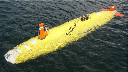
Quando i nostri veicoli autonomi sono chiamati ad operare sulla super-ficie dell’acqua vengono denominati unmanned sea/surface vehicle, o sem-plicemente USV. Sono invece detti unmanned undersea/underwater vehicle, UUV, se operano sotto la superficie. Questi veicoli possono essere utilizzati per abbattere molto i costi sullo studio dei mari, come lo studio delle correnti, le composizioni chimiche, le maree, gli tsunami. Sono utili anche in caso di disastri per effettuare il monitoraggio della zona, ad esempio la diffusione di una chiazza di petrolio in un incidente navale. Possono essere adoperati an-che per ricognizioni marine al fine, per esempio, di effettuare stime sui danni e sulla pericolosità per l’ambiente di scavi marini, ma anche per raccogliere informazioni utili alla preparazione di un piano per l’invio di sommozzatori in presenza di relitti. Possono essere utilizzati anche per effettuare ricognizioni a seguito di incidenti aerei, come avvenuto dopo l’incidente dell’Air France Flight 447, dove è stato impiegato un AUV Abyss, un UUV realizzato dalla Hydroid [23], per effettuare ricognizioni sottomarine.
Figure 2.4: Abyss nel suo ambiente naturale.
Anche in questo caso le dimensioni possono variare molto, da piccoli radio-comandi atti a raccogliere dati scientifici autonomamente e a basso costo, a vere e proprie barche dotate di maggior autonomia, braccia meccaniche, radar
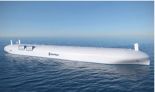
8 CHAPTER 2. I VEICOLI AUTONOMI e potenti motori. (Si vedano ad esempio i veicoli realizzati dalla SeaRobotics [24]). Di recente la Rolls Royce ha annunciato di voler sviluppare navi cargo controllate da remoto [25]. Iniziativa probabilmente collegata al recente fi-nanziamento di 3.5 milioni di Euro da parte dell’Unione Europea di un pro-getto chiamato Maritime Unmanned Navigation through Intelligence in Net-works [26], il cui scopo è proprio quello di sviluppare e verificare il concept di una nave completamente autonoma, guidata cioè dai sistemi on-board instal-lati sulla nave e controllata da un operatore remoto da una stazione di terra. Il progetto si prefigge l’obiettivo di realizzare navi prive di equipaggio con lo stesso livello di sicurezza delle attuali navi con equipaggio, ma l’assenza di quest’ultimi permetterebbe di abbassare i costi di gestione della flotta, permettendo la costruzione di navi più leggere, più economiche e capienti. Ovviamente, come per le controparti stradali, le normative attuali non per-metterebbero ancora a queste navi di poter navigare, ma probabilmente per quando cominceranno le prime sperimentazioni qualcosa sarà già cambiato.
2.3. UNMANNED SPACE VEHICLE - USV 9
2.3
Unmanned Space Vehicle - USV
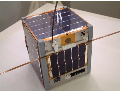
Gli Unmanned space vehicle chiamati anche unmanned spacecraft, sono probabilmente la categoria più antica di veicoli autonomi. Rientrano in questa categoria infatti tutti i satelliti che orbitano intorno alla terra, a par-tire quindi dal primo satellite mandato nello spazio, lo Sputnik 1 del 1957. Da allora in questo settore abbiamo fatto molti progressi. Oggi se da una parte ci sono ancora progetti di un certo spessore economico come il Boeing X-37 [27], ci sono anche progetti che cercano di realizzare satelliti relativa-mente economici e facili da programmare come CubeSat, che permette di predisporre una semplice piattaforma per effettuare ricerca nello spazio, a patto di trovare un passaggio [28, 29].
10 CHAPTER 2. I VEICOLI AUTONOMI
2.4
Unmanned Aerial Vehicle - UAV
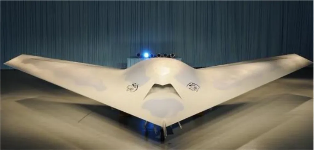
Gli unmanned aerial vehicle, volgarmente detti droni, termine però che sempre più viene criticato dagli esperti del settore perché riduttivo nei con-fronti di ciò che queste macchine possono fare, sono quei veicoli autonomi che operano in aria. Sono utilizzati in una variegata gamma di applicazioni. Ad esempio nel settore militare, veicoli avanzati come il Predator, il Reaper o il Global Hawk, svolgono una grandissima varietà di missioni, fra cui ric-ognizione, spionaggio e bombardamenti. Questi veicoli vengono spesso men-zionati con la sigla di UCAV, ovvero unmanned combat aerial vehicle, o RPA, remotely piloted aircraft, aeromobili a pilotaggio remoto, in quanto ad oggi ancora necessitano una stazione esterna che controlli il mezzo.
Figure 2.7: Il Boeing Phantom Ray alla sua presentazione ufficiale.
Complice la miniaturizzazione dei sensori e la riduzione dei costi, spinti dall’evoluzione del settore smartphone, anche il settore civile vede un uso sempre più massiccio di questo tipo di veicoli. L’evoluzione dei motori elet-trici, diventati piccoli, efficienti e facili da utilizzare grazie all’elettronica di controllo (ESC: Electronic speed control [30]), ha rivoluzionato il mondo del radiomodellismo, portando vantaggi nella costruzione di piccoli UAV ef-ficienti, spesso chiamati MAV, Micro Aerial Vehicle. Inoltre la continua evoluzione di queste componenti fondamentali per il controllo e l’automatizzazione permette alle applicazioni civili di avere una crescita continua. Questa
tipolo-2.4. UNMANNED AERIAL VEHICLE - UAV 11 gia di veicoli è spesso usata per attività come il monitoraggio ambientale, la si-curezza, ma anche utilizzati nel settore agricolo per massimizzare l’efficienza, in fasi come la semina e la distribuzione di fertilizzante, abbattendo i costi. Molti altri settori potenziali sono ad oggi ancora inesplorati, per limiti di natura tecnologica o burocratica. Hollywood e CNN ad esempio pressano la FAA per avere un regolamento certo e con la possibilità di usare agevol-mente questi veicoli [31, 32]. Solitaagevol-mente in campo civile si usano mezzi molto semplici da controllare e relativamente poco costosi come i multicopteri. I multicopteri sono infatti piccoli veicoli aerei, dotati di più eliche, dalle tre alle otto solitamente. Sono molto diffuse le configurazioni a quattro eliche per la loro semplicità e il loro costo basso, ottime per volare in indoor o sor-volare a bassa quota spazi pubblici. Sono meccanicamente più semplici di un elicottero anche se meno efficienti. In piccole dimensioni la semplicità mecca-nica permette di compensare appieno la minore efficienza. In futuro attività come search&reascue, in caso di incidenti in aree inaccessibili, il monitor-aggio ambientale, la costruzione di mappe tridimensionali, potranno essere svolte in modo autonomo da queste macchine avanzate. Già oggi vengono utilizzati in ambito giornalistico o da parte delle forze dell’ordine per avere informazioni tattiche in tempo reale quando chiamati ad affrontare situazioni difficili. Molti centri di ricerca, come il DLR German Aerospace Center, sper-imentano l’inserimento di braccia robotiche per manipolare l’ambiente cir-costante [33]. L’ETH ha mostrato come uno sciame di quadricopteri possa essere usato per la costruzione di strutture complesse [34], grazie ad una corretta coordinazione e suddivisione del lavoro. C’è una grande varietà di applicazioni che si possono svolgere con questi veicoli. Servono quindi avan-zamenti software importanti per realizzare applicazioni complesse, serve un modello ingegneristico con il quale progettarli.
12 CHAPTER 2. I VEICOLI AUTONOMI
Figure 2.8: DJI Phantom Vision, un prodotto commerciale di gran successo.
Figure 2.9: Alcuni prodotti della gamma AscTec, molto apprezzati in ambito di ricerca.
2.4. UNMANNED AERIAL VEHICLE - UAV 13
2.4.1
Regolamentazione italiana ENAC per gli APR
In Italia gli UAV sono chiamati APR, Aeromobili a pilotaggio remoto. A cercare di regolamentare l’uso di questi veicoli, che, per quanto utili, pos-sono rischiare di risultare anche molto pericolosi (ad esempio violando lo spazio aereo di un veicolo da trasporto civile o perdendo il controllo rischi-ando di ferire o danneggiare persone o cose a terra), ci penserà l’ENAC, Ente Nazionale per l’Aviazione Civile. Un documento pubblicato dall’ENAC e disponibile sul portale ufficiale contiene indicazioni specifiche sulle autor-izzazioni necessarie per i piloti, sull’equipaggiamento, sulle certificazioni da ottenere prima del volo. L’Italia è dunque uno dei primi paesi ad adottare una normativa ufficiale sul tema, dimostrando un’ottica lungimirante per evitare di arrivare in un secondo momento impreparati e di dover gestire la situazione quando ormai troppo tardi.
Chapter 3
I sistemi autonomi
Sia nel settore civile che in quello militare la ricerca punta soprattutto alla realizzazione di veicoli che per svolgere il loro compito richiedano sempre meno l’intervento dell’operatore. Inizialmente i sistemi a bordo si occupa-vano semplicemente di semplificare il controllo, evolvendosi poi in sistemi capaci di svolgere funzioni avanzate come mantenere la posizione a fronte di forze di disturbo, seguire percorsi prestabiliti o acquisire i dati nel momento opportuno. Ma si cerca ancora più autonomia, sistemi che possano pren-dere vere e proprie decisioni basandosi sulla loro conoscenza a priori. Quale percorso è meglio seguire, quale azione è meglio effettuare. Quali degli obbi-ettivi prefissati ha maggior priorità e quale può essere scartato. L’intervento dell’operatore si pone pian piano su un livello sempre più astratto, la cui unica funzione è dare indicazioni, una conoscenza di base ed assistere al compimento degli obbiettivi come una figura passiva. Per ottenere questi risultati manca ancora molto lavoro da fare, ma una prima proposta è quella di usare i linguaggi ad agenti che offrono un modello concettuale molto vicino al risultato desiderato.
16 CHAPTER 3. I SISTEMI AUTONOMI
3.1
Linguaggi ad agenti e sistemi di veicoli
autonomi
Cos’è un agente? Un agente è una entità autonoma che incapsula il con-trollo. Tutto ciò che può essere scambiato da un agente sono solo dati come conoscenza ed informazioni. La loro autonomia si traduce quindi in una pro-attività, cioè la capacità di modificare l’ambiente di propria iniziativa e non solo come reazione ad un cambiamento. Per poter far ciò gli agenti devono possedere una conoscenza dell’ambiente che li circonda, del contesto in cui si trovano ad agire. Devono cioè possedere una propria rappresentazione del mondo. Ma in un mondo non statico ma dinamico gli agenti hanno la ne-cessità di dover percepire eventuali cambiamenti nel mondo, soprattutto per sapere quali azioni possono eseguire o conoscere se le proprie azioni hanno portato gli effetti desiderati. La componente reattiva non viene quindi meno negli agenti, che possono divenire per scelta anche puramente reattivi. Qual-siasi sia però il comportamento di un agente alla fine le sue azioni porteranno sempre ad un cambiamento intorno a se. Sia che le sue azioni vadano ad in-fluenzare altri agenti, sia che vadano a modificare l’ambiente. L’autonomia di controllo potrebbe permettergli di avere una sorta di intelligenza che li aiuterebbe a governarsi, ma essa non è necessaria alla loro autonomia. Poiché un agente incapsula il controllo, esso può agli estremi divenire anche mobile se il suo controllo può in qualche modo essere indipendente dall’ambiente. Possedere un autonomia permette inoltre ad un agente di migliorarsi, im-parando ed acquisendo nuove capacità. Possono addirittura, secondo una definizione più forte di agente, avere componenti mentali come idee, desideri, intenzioni, conoscenza [35]. Essi sono, in ultima analisi, interattivi, sociali, pro-attivi e reattivi. Sono caratterizzati da una conoscenza dell’ambiente e del contesto. Possono avere obbiettivi o compiti da completare. Possono essere intelligenti o mobili. Essi vivono in società composte da altri agenti, dette MAS, dove interagiscono tra loro tramite comunicazione e modificano l’ambiente con le loro azioni. Un sistema multi-agente è un insieme di agenti, dotati ciascuno della propria autonomia, che collaborano tramite scambio di informazioni. Infatti un sistema a singolo agente non esiste in principio.
3.1. LINGUAGGI AD AGENTI E SISTEMI DI VEICOLI AUTONOMI17 Da un punto di vista filosofico infatti l’autonomia ha senso solo se un in-dividuo è immerso in una società e nel caso degli agenti quindi un MAS. All’interno di esso questi agenti autonomi comunicano tramite scambio di dati, modificano il mondo tramite azioni e sono sensibili a queste variazioni tramite le percezioni. L’interazione di queste singole entità, che potrebbero avere comportamenti anche semplici, fa emergere nel sistema il comporta-mento desiderato. Senza che le singole entità siano per forza a conoscenza dell’obbiettivo comune del sistema.
3.1.1
Esempi di applicazione di MAS ad Unmanned
Sys-tems
Prima di mostrare le applicazioni svolte in quest’ambito è giusto fare una precisazione. Ad oggi molti unmanned vehicle come detto precedentemente non sono degli autonomous vehicle ma possono anche essere dei semplici re-mote piloted vehicle. In questi casi il sistema svolge il cosiddetto compito di copilot, semplificando all’utilizzatore l’esecuzione di certe azioni ponendosi come intermediario. Inoltre soprattutto a livello civile quando questi veicoli sono piccoli e non dispongono di sufficiente capacità computazionale hanno a bordo una ridotta logica di controllo, il copilot per l’appunto od una sua versione più semplice, affidando poi ad una stazione a terra (GS) le funzion-alità più avanzate. Ad esempio per i droni commerciali, quando si imposta una rotta da seguire la stazione a terra si occupa di tracciare un percorso fra i punti inseriti e di calcolarne tutti i parametri. In seguito invia al drone solo lo specifico vettore da seguire per giungere al punto successivo della rotta. Quindi si potranno avere sistemi multi-agente dove gli agenti saranno caricati direttamente sugli UV o sistemi multi-agente caricati sulla GS che avrà il compito poi di guidare gli UV. In [36] Magnusson, Lande’n e Doherty utilizzando il framework JADE per la costruzione di una simulazione, nella quale gli UAV effettuavano le azioni e comunicavano fra loro tramite azioni di comunicazione standardizzate, come FIPA ACL speech acts, hanno simulato la possibilità di realizzare un sistema multi-agente dove ogni agente giace su un UAV. Ognuno di esso ha la possibilità di pianificare le comunicazioni da
18 CHAPTER 3. I SISTEMI AUTONOMI effettuare con altri agenti, le azioni da eseguire ed un piano per recuperare in caso di imprevisti come ad esempio un problema nelle comunicazioni. Questi agenti, fanno uso di tecnologie di theorem proving per pianificare ed eseguire le proprie azioni. Essi infatti si affidano ad una estensione delle Temporal Action Logic. Tramite un deduction theorem prover automatizzato genera e revisiona un piano in linea con l’ambiente circostante che è poi eseguito da un algoritmo STNU che dispacci le azioni in accordo ai vincoli temporali. Infine queste dispacci delle azioni vengono presi dalla piattaforma JADE che le esegue sulla piattaforma fisica del robot (simulato) in questo caso. Nello scenario proposto hanno dimostrato la flessibilità con cui un UAV incaricato di scannerizzare una cella in cerca di persone, a seguito di una perdita di connessione con il controllo a terra ha rapidamente riformulato il piano per appoggiarsi ad un secondo UAV che facesse da tramite per lo scambio di messaggi. In [37] si discute l’idea di come realizzare un UAVICS (UAV In-telligence Control System) introducendo il concetto di MAS nel suo design, che viene poi chiamato UAVTICS (UAV Team Intelligence Control System). In particolare provano a costruire la struttura del MAS e i gli agenti che ne faranno parte. Ad esempio il Launch Control Agent che si occupa delle azioni di preconfigurazione e decollo degli apparecchi, il Command and Surveillance Center Agent (CS-A) composto a sua volta da altri quattro agenti e che in-sieme supervisionano il corretto svolgimento della missione da parte del team di UAV. Il Communication Module Agent che deve occuparsi della comuni-cazione fra il UAVT Agent e il CS-A. UAVT Agent che rappresenta l’agente che si occupa del team di UAV e che è realmente composto da un insieme di Single Unmanned Air Vehicle Agent.
3.1. LINGUAGGI AD AGENTI E SISTEMI DI VEICOLI AUTONOMI19 Research on the UAVTICS Based on Multi-agent 75
mission date;
Communication Management Agent(CM-A): its function is
mainly about managing the information from the superior, neighbor unit.
UAVT Agent (UT-A). The agent is composed of some single UAV agents.
Every single agent communicates and cooperates with each other according to
some stated rules, and keeps the real-time connection with Communication
Management Agent. UT-A is the direct unit to carry out the mission, it carry
out its work according to the pre-bonded date and make decisions
accord-ingly. Its decision level is lower than MrP-A’s in LSC-A.
Communication Module Agent (CM-A). This unit is mainly composed of
secondary planet and signal receiving station on the ground. Its job is the
communication between CS-A and UT-A.
Fig. 1. The UAVTICS model based on MAS
3 The Communication and Cooperation Rule of UAVTICS
Excepting for the voice communication between the human-machine integration
Agent, FIPA ACL format (an Agent communication language in intelligence physical
fund organization) is used widely by the information transmitted in date form. The
content and ontology of FIPA ACL message uses XML (eXtensible Markup
Lan-guage) code. Communication among the Agents obeys FIPA communication
[2]. The
agent in CS-A communication though LAN; different kinds of wireless and lineate
method is used among CS-A, LC-A and superior command system; CS-A connects
with ground station of secondary planet and communicate with UAVT through the
secondary planet date-line.
Del CS-A viene descritta l’architettura del suo Fly-Control Agent, pen-sata con l’idea principale di seguire un “approccio di integrazione uomo-macchina”. Anche l’architettura del Single Unmanned Air Vehicle Agent viene trattata. In questo caso si è scelto di mantenere un architettura ispi-rata al modello BDI.
78 N. Guo, J. Lv, and J. Yu
stores the date of faith aggregate for the display and decision; Tele-memory stores
date and cyclostyle of Tele-message; Know-memory stores the preparative knowledge
of IMA as arithmetic, consequence rules, communication knowledge. XML format is
used in all the three above.
5 Structure Design of Unmanned Air Vehicle Team Agent
Because of the complexity of the aerial warfare circumstance, it is insufficient in
actual combat with a single Unmanned Air Vehicle executing mission. Building an
Unmanned Air Vehicle Team is essential. We construct a multi-agent system which
can accomplish its mission by cooperating with every sub-agent. Firstly a single
Un-manned Air Vehicle Agent’s structure is given.
5.1 Structure Design of Single Unmanned Air Vehicle Agent
When we select method of Agent structure design, structure BDI was taken into
ac-count. Because structure BDI uses observe-think-act executing manner, which can
obviously express Agent’s Beliefs, Desires, Intentions and Programming.
Further-more structure BDI has perfect theory, flexibility and response. So we design the
structure of single Unmanned Air Vehicle Agent based on the BDI.
The structure of single Agent was shown as Fig.3:
Fig. 3. The structure of single Agent
In the model BDI=( R,K,G,P,E,IP,OP,T,F,ILA,OLA,E).
Thereinto:
R,K,G,P,E are abstract databases, they can be gauged by different mission.
Reasoning(R) shows the reasoning and decision-making course of Unmanned
Air Vehicle. During this course, Unmanned Air Vehicle makes decisions
ac-cording to the information of its own, information offered by other Unmanned
Air Vehicles and existing knowledge storage.
Knowledge storage (K) is the finite set of database, which corresponds with
the Beliefs of BDI. It shows the war field circumstance and the information of
20 CHAPTER 3. I SISTEMI AUTONOMI Inoltre viene spiegato come all’interno del team solo un agent ricopre il ruolo di leader (lead plane agent) e gli altri sono solo compagni (wing plane agent). Di questi è il leader che si occupa di comunicare con il CS-A ed ha il compito di decidere quando attaccare. Tutti gli altri agenti insieme al leader si limitano a scambiare le informazioni ottenute tramite i sensori sull’ambiente circostante e le distribuiscono in broadcast. In [38] si prova a comprendere quali siano i problemi nella realizzazione di un vero e pro-prio surrogato del pilota tramite agente BDI, implementato in JACK, in modo da ottenere una completa autonomia e non aver più quindi bisogno di affiancare ad un UAV una stazione a terra per il supporto alle decisioni. Questo permetterebbe di ridurre la presenza dell’uomo salvo condizioni in cui strettamente necessario, inoltre può portare in futuro ad una semplice implementazione di team di UAV completamente autonomi. Nelle simu-lazioni si è verificata la capacità di un team di dialogare correttamente e si sono verificati i corretti comportamenti. Tramite una prova reale si è di-mostrata inoltre la capacità del veicolo di gestire il proprio volo in modo sicuro e autonomo, terminando la missione in caso di necessità. Questo sis-tema in futuro potrebbe prevedere la possibilità di applicazione di tecniche di volo avanzate difficilmente ottenibili tramite sistemi di controllo standard, ad esempio nel volo di un aliante che deve prendere in considerazione costi e benefici di diverse rotte in base alla conformazione del terreno. [39] in-troduce l’idea di un framework, che viene chiamato UAVAS, per descrivere il comportamento intelligente degli UAV tramite agenti specificati con Ja-son/AgentSpeak. Questo framework verrà esteso per creare una analogia in cui un agente Jason viene visto come un umano seduto all’interno del cockpit di un classico veicolo pilotato. Nell’astrazione creata questo modello viene realizzato:
3.1. LINGUAGGI AD AGENTI E SISTEMI DI VEICOLI AUTONOMI21
4
Fig. 1. PRY system, used for 3D spatial maneuverings.
that makes an analogy where Jason Agents are seen like human people inside a manned aerial vehicle. More specifically, while an manned aerial vehicle is tripulated by humans that controls the manned aerial vehicle through control panel commands and communicates with each other or with remote personal, in an analogous conception, an UAV is “tripulated” by Jason Agents that operates the UAV by means of a action protocol and communicates with each other or with remote systems. In this abstraction, the following modelings are created:
Table 1. UAVAS modeling abstractions.
UAVAS Model Manned Aerial Vehicle
UAV Agents models Aerial Vehicle Tripulation
AgentSpeak .ASL File models Crew Intelligence and Flight Plans
Action Protocol models Aerial Vehicle’s Commands
Agent’s Environment models Pilot Cabin
UAV models Manned Aerial Vehicle
The UAV Agents inherit the architecture implementation from Jason Agents and so provided with an API to receive perceptions, execute actions, send messages, and reason about plans in UAV’s context. The UAV Agents are within a Jason MAS and can interact with each other in order to transmite relevant informations, as we can analogously see in manned aerial vehicles when pilots, co-pilots and commissioners interacts and talks with each other. Jason Agent’s intelligent behaviors are developed through AgentSpeak AOP language in .ASL Files, being the abstractions for manned aerial vehicle’s Tripulation Intelligence and Flight Plans. Also, in the manned aerial vehicle, a set of Aerial Vehicle’s Commands and controllers (i.e. ailerons, elevator, rudder) is available to do general maneuverings and flight managements. In the model, Il modello concettuale di questo framework può essere riassunto dalla seguente figura:
6
Fig. 2. UAVAS model abstractive design.
– rollhValuei – When an Agent executes this action, the UAV is requested to configure the inclination/ailerons to the specified argument Value; – yawhValuei – When an Agent executes this action, the UAV is requested to
configure the tail/rudder to the specified argument Value;
– acceleratorhValuei – When an Agent executes this action, the UAV is requested to configure the collective/accelerator to the specified argument Value;
– moveTohPi – When an Agent executes this action, the UAV is requested to move to the given geographic point P, clearing any previous geographic points and canceling patrol mode;
– doPatrolhPListi – When an Agent executes this action, the UAV is re-quested to cyclically patrol the geographic points in the given list PList; – goHome – When an Agent executes this action, the UAV is requested to move
to its initial position (when the system has booted);
– setHomehPi – When an Agent executes this action, the UAV is requested to override its initial position, assuming the given geographic point P as the new one;
– addWayPointhPi – Internally, an UAV has a FIFO list of geographic points to be achieved in an orderly manner. When an Agent executes this action, the UAV is requested to add a new geographic point P in this internal list; – requesthdestinatary,logicExpressioni – When an Agent executes this action, the UAV is requested to perform a request to another UAV, about to bring to true the logic expression parameter;
Il firmware dell’UAV è direttamente connesso all’agent tramite un collega-mento asincrono detto UART (Universal Asynchronous Receiver/transmitter). Una serie di classi intermedie trasforma le azioni dell’agente in valori inter-pretabili dall’UAV. Un semplice decollo, simulato all’interno del simulatore RC-Sim, può essere descritto con il semplice codice:
+!takeOff : status(ok) <-collective(8);
22 CHAPTER 3. I SISTEMI AUTONOMI .wait(10000);
collective(4); !doTheMission.
In [40] si mettono a confronto due approcci diversi con il quale applicare tecnologie agent-based per il controllo di un sistema di UAV, entrambe im-plementate in JACK [41]. In uno si applica un approccio standard in cui si aggiunge un livello sul sistema di controllo di volo, che girerà su una pi-attaforma separata e dialogherà con l’autopilot tramite un interfaccia fornita all’agente. First Alternate Second Alternate Alpha 1 Launch Point Command Post Alpha 2 Decision Point Recovery Point Backup RC Pilot
Figure 1: Avatar UAV Flight Path: At Alpha 2 the AUC (Autonomous UAV Controller) selects one of the alternate waypoints based on the local wind con-ditions. Failure of the AUC will result in the aircraft flying to the decision point and then returning home
was flown to test wind conditions and aircraft visibility. Then the team proceeded to setup the Avatar with way-point data and conduct a ‘walk around’ test. This involved, essentially, switching on the FCS and JACK agent system, carrying the UAV around the flight course, traversing the waypoints the UAV is expected to intercept during its flight, and monitoring the FCS and JACK agent behaviour from the GCS. This testing method can be likened to hardware-in-the-loop testing, and might also be considered as a very low speed, low altitude flight test.
After testing was completed and minor configuration is-sues rectified, the flight test program was conducted. The same test was conducted two times: firstly with the iPAQ (housing the agent) on-board the plane (ie. directly con-nected to the FCS), and secondly with the iPAQ off-board and connected to the GCS (ie. communicating with the FCS over the GCS wireless link). The purpose behind the off-board test was simply to see if the agent platform can, in fact, operate off-board, thus allowing possibilities for more powerful processor platforms not restricted by size or power supply. Although the vision for the project is for the agent and FCS sub-systems to be both on-board the Avatar and have no dependance on radio communications to operate, investigating the off-board configuration was still useful.
The UAV was hand launched and manually piloted to a stable altitude and attitude by an expert radio-control (RC) pilot. It was then switched over to ‘UAV mode’, and proceeded to autonomously intercept the waypoints. All flight trials were safely and successfully conducted and an examination of the flight logs indicated that the agent had made the correct decisions at the correct times based on the data it received from the FCS.
Figure 2 shows some pictures taken during the test flight.
4.
AGENT DESIGNS
4.1
Overview
The ultimate aim of our agent-based system is to achieve robustness and efficiency, but also for the design to be
intu-Figure 2: The Codarra Avatar during its test flight in Greytown, Melbourne, Australia, 5 - 7 July, 2004.
itive for designers and domain experts.
Two designs addressing the same mission parameters were concurrently developed. The “control systems approach” (§4.3) was developed to exhibit a simple, bottom-up, purpose built design, and as a means to compare to the “cognitive approach” (§4.4), which is a more sophisticated, top-down design, and was the system eventually used for the flight trials. In both designs, the agent-based mission manage-ment system sits on top of the control hierarchy, as will be described in the next section.
4.2
The Agent-FCS System Architecture
Attitude Managment
ie . Autopilot , auto- stabilisation
Trajectory Management ie . FMS , control of vehicle Autopilot 3-axis stabilised serial link JACK Agent running on HP iPaq
Control Hierarchy On-board Controller
and
Mission Management System
Avatar UAV Mission Managment agent-based planning and control
Figure 3: Agent - FCS Architectural design Figure 3 [17] illustrates the system, and the respective hi-erarchical positions of the agent and FCS sub-systems within it. The FCS provides data about the state of the environ-ment and the platform at 1 Hz. This data set includes GPS positioning data, control deflections, and aircraft state pa-rameters. The FCS accepts many commands that provide the capacity to control the aircraft through waypoint setting or by interacting directly with the control surfaces. For the first trial only the waypoint commands were used. An inter-face was provided for the JACK agent to access data from
22
In questa implementazione l’agente ha una struttura semplice e minimal-ista che si rifà ad una struttura feed-back control loop. In tal modo si ottiene una implementazione robusta ed efficiente anche se non abbastanza flessibile da poter gestire più compiti a parte quelli che richiedo una singola decisione o azione da parte dell’agente.
3.1. LINGUAGGI AD AGENTI E SISTEMI DI VEICOLI AUTONOMI23
the FCS. The agent was written in JACK, and hence
oper-ates inside a JACK Kernel that runs asynchronously with
respect to the interface. This presented many
synchronisa-tion and integrasynchronisa-tion issues.
4.3
Design 1: A Control Systems Approach
The first design that was implemented and tested in
sim-ulation was a simple, straight control-path design. The
de-sign’s main premise is simplicity and minimalism, and
fol-lows a traditional feed-back control loop structure.
A brief description of the main design elements follows.
A diagram of this design (consisting of JACK constructs) is
shown in Figure 4.
Data triggered control mechanism As soon as data is
presented to the agent in the form of packets, a linear
control sequence is triggered. This sequence consists
of, firstly, acquiring the data and putting it into the
relevant JACK belief sets. Then, depending on the
current situation (eg. intercepted a waypoint, reached
a goal waypoint, etc.), actions are taken, which consist
of either setting a new waypoint based on stored data,
or performing calculations which will be later used to
set waypoints.
Synchronous processing As there is a single, linear thread
of control, complications and problems associated with
asynchronous control are eliminated.
However, for
more complicated missions, asynchronous designs may
be required from an implementation perspective, and
desirable from a design perspective.
No unnecessary constructs As mentioned, the objective
of this particular design is simplicity, and as a result
many unnecessary modules were removed. Superfluous
elements in a software system, in particular a real-time
control system, are generally undesirable and should
be avoided to ensure robustness and efficiency.
Immediate response Due to the simplicity of the design,
which posts the minimal number of events and employs
the minimal number of plans, cycle time is very short
and hence results in a more reactive system.
This design is very efficient and robust for the purpose
it was intended for. However, it is not flexible enough to
handle different tasks outside of singular-decision type tasks
(ie. tasks which only require one decision or action from
the agent). This is obviously not ideal if a flexible,
multi-purpose system is desired. However, according to the
min-imalist philosophy of robotics championed by researchers
such as Brooks [5, 6], simple and purpose-built designs can
sometimes be more effective, robust and consequently more
powerful.
4.4
Design 2: A Cognitive Modelling Approach
The BDI language, JACK, already provides programming
level constructs (belief, plan, event, capability) that map
in-tuitively, if not entirely reliably, to everyday notions those
constructs that are used by pilots to describe their mission
control decision-making. A further architectural design layer
was added that partitions the autonomous mission control
software into four primary modules that map to the four
el-UpdatePilotData (plan) FCSDataUpdate (event) handles windSpeeds
( WindSpeed belief type)
interceptedWpts
( Waypint belief type )
SituationAssesment (plan) handles reads modifies modifies StartSituation Assesment (event) UpdateAfterDecision (plan) handles modifies TimeToMake Decision (event) SendWaypoint (plan) handles Command Acknowledge (event) Successful Change Made (plan) handles posts waits for
Figure 4: A Control System Design approach for
the JACK AUC agent system. The main control
loop triggers the FCSDataUpdate event, which starts
the simple, linear control process of acquiring data
and performing appropriate actions depending on
the UAV’s situation.
ements of Boyd’s OODA loop model
2, a model widely used
in the military and is being adopted by businesses to model
competitive activity. Each module reflects a human-oriented
process. The model consists of four modules: Observe,
Ori-ent, Decide and Act, which are iteratively executed to
per-form the desired control.
A detailed explanation of the functioning of these modules
is beyond the scope of this paper but briefly the four primary
modules are:
Observe Process the data arriving from the flight control
system. Perform axes and units transformations, filter
data searching for important events and relationships,
trigger events, assert beliefs. The result of observation
is an updated set of beliefs about the world and events
to respond to.
Orient Process beliefs and observation events in the
con-text of current intentions, mission goals, and beliefs.
Construct assessments—reasoned context sensitive
be-liefs about the state of the world in the context of the
current mission.
Decide From the assessments (and if necessary the
obser-vations) decide upon a course of action. The aim is to
reason about appropriate actions from the more
ab-stract view of the world provided by the assessments
but the option to access the observations remains. A
decision about an appropriate course of action might
be considered to be the mission-level characterisation
of the agents intent. An intent which is accorded detail
in the following step.
2
Sometimes the software modules are described
synony-mously as situation awareness, situation assessment, tactical
selection, and standard operating procedures
23
L’altra implementazione invece realizza un controllo autonomo ispirato ad un modello decisionale umano (nello specifico basato su OODA, observe-orient-decide-act). Questa modellazione permette di avere un sistema scal-abile ed estendibile. Basta infatti modificare le giuste fasi aggiungendo le funzionalità richieste senza dover stravolgere la struttura. Inoltre questa modellazione permette un effettiva collaborazione in caso si abbiano team di UAV. Ad esempio il modulo ORIENT di un agente può rappresentare un ingresso per il modulo OBSERVE di tutti gli altri.
24 CHAPTER 3. I SISTEMI AUTONOMI
Act Invoke the tactics that fly the aircraft. These plans
provide the detailed pre-scripted recipes for achieving
the desired mission.
Figure 5 graphically represents the architecture as it was
implemented for the first round of flight-trials. The choice
of architecture has the following properties:
Human Cognitive Model Based Architecture An
ar-chitecture based on a human cognitive model allows
the developer to leverage the folk-psychological
famil-iarity and intuitiveness. It seems obvious where future
functionality will reside and how the system
integra-tion will be performed. The design is simplified,
al-though possibly at the expense of run-time complexity.
Asynchronous processing The software provides
asyn-chronous processing between the modules in the OODA
loop. The decision was taken because: of the
modu-lar nature of the OODA components; the data-driven
nature of the design; and the potentially different
tem-poral scales involved in the four OODA components.
Generation of abstract world state The design features
an orient or situation awareness phase that generates
a more abstract representation of the world state from
the sensory data. This abstract world state simplifies
decisions about tactics but requires that care is taken
with the design.
Belief Triggered The design is largely data driven. In
JACK terms it would be more accurate to describe the
design as belief triggered. That is the belief data base
causes the execution of most of the agent processing.
4.5 Discussion
It is noteworthy that the concepts and ideas for the
con-trol of UAVs presented in this paper are equally applicable
to other unmanned vehicles, such as unmanned ground
vehi-cles (UGVs) (eg. [3]) and autonomous underwater vehivehi-cles
(AUVs) (eg. [7]).
The first design, inspired by a minimalist control systems
approach, illustrates there may exist a simple and
straight-forward solution for many problems. The use of complex
representations can, in many cases, be avoided and the
sys-tem can consist of reactive, purpose-built elements. For the
first design, the system only performs the task of
navigat-ing to a specific location and decidnavigat-ing on which direction to
travel to. However, even small changes to the system can
require a significant overhaul of the design and
implemen-tation. For example, if the UAV was required to navigate
a shortest path (ie. path planning), then different modules
for waypoint generation and command assignment, for
ex-ample, would have to be developed. In such a case, the
purpose-built nature of the original design may not be able
to accommodate the new features/extensions and a
com-pletely new design may have to be developed.
The second design was inspired by human surrogacy, which
is a notion that proposes that vehicle control systems can
act, sense, behave and decide the way humans nominally do.
The advantage of this design, based on the OODA loop, is
that subtasks (ie. Observe, Orient, Decide, Act) are
delin-eated by modules, and conform to good software engineering
Data from Flight Control System
OBSERVE (Situation Awareness)
ORIENT (Situation Assessment)
DECIDE (Tactics Selection)
Beliefs about Situation
Beliefs about Assessed Situation
ACT (Tactics Implementation)
Course of Action
Commands to Flight Control System
Position Signal Strength
Speed (wind and ground speed) Altitude Waypoint proximity Weather monitoring . . . Select a Waypoint Declare an Emergency . . . . . . Fly to Waypoint Return to Base Set Speed . . .
Figure 5: Cognitive Modelling (OODA) design
ap-proach for the autonomous UAV controller.
The
four primary modules implement a data-driven
com-putational implementation of Boyd’s OODA loop
model of command decision making superimposed
on the BDI language constructs of JACK.
principles of strong cohesion, encapsulation, and low
cou-pling. Moreover, the framework allows for extensibility and
scalability. Depending on different tasks or missions, the
modules can be modified to suit. Using the path planning
example mentioned earlier, the OODA loop would be
modi-fied in the Decide and Act modules by adding the capability
of generating and issuing waypoints to the FCS, rather than
deciding upon predetermined waypoints as was the
require-ment in this first test flight.
In addition to flexibility, the OODA loop approach allows
for effective team cooperation. Multiple UAVs forming a
collective, or team, can all individually run OODA loops
that interact via module interfaces. For instance, the orient
module of an agent can be observed by one or more other
agents, and the action of other agents can in turn influence
the decision of the agent.
Further details of the lessons learned from the software
design exercise are available in a forthcoming report [13].
5. RELATED WORK
This work borrows heavily from the experiences of
de-veloping agents for simulation described in
§2.2, and from
the general state of UAV controller design particularly those
with a cognitive component, some of which are mentioned
in
§2.1. The DyKnow framework by Doherty and Heintz
[10], for example, is essentially a signal-to-symbol
trans-former that, amongst other features, continually monitors
perceived signals and creates higher-level cognitive objects
that are relationally linked to each other. These abstract
objects are continually updated in real-time by maintenance
of predefined hypotheses that are defined by a domain
ex-24
In [42] si prende invece in esame l’uso di Unmanned Groud Vehicle sim-ulati in un caso di pursuit-evasion war game. In questa simulazione due agenti collaborano per la cattura di un nemico. Viene realizzato per il caso un modello di sistema multiagente basato su una rete di Petri ad oggetti. Anche in questo caso si tratta di agenti BDI e tramite l’uso delle reti di Petri ad oggetti è possibile fare un analisi formale del modello così da poter ver-ificare le proprietà di questo. Ad esempio il modello astratto di un singolo agente UGV è descritto dalla seguente rete di Petri.
3.1. LINGUAGGI AD AGENTI E SISTEMI DI VEICOLI AUTONOMI25
2. A Novel Object-Oriented Petri nets
Petri nets are a graphical and mathematical modeling
tool applicable to many systems that exhibit concurrency
and synchronization [9]. The ordinary Petri nets easily lead
to the so-called state-explosion. In order to solve the
com-plexity and state-explosion, a novel Object-Oriented Petri
nets (OPN) are set up. OPN can tersely and independently
represent all kinds of resources in a complex system,
in-crease the flexibility of the model. In the OPN model, a
system is composed of mutually objects and their
intercon-nection relations.
Definition 1 OPN is a 2-tuple, OP N = (O, Gate), where
O
is a finite set of physical objects in the system, O =
{O
1, O
2, . . . , O
i}; Gate is a finite set of special places and
represents message passing channels among physical
ob-jects.
Definition 2 O
iis a 7-tuple, O
i= (P, T, IT, OT, F,
E, C)
, where P is a finite set of places in the system,
P =
{p
1, p
2, . . . , p
j}; T is a finite set of transitions,
T =
{t
1, t
2, . . . , t
k}; IT (Input Transition) and OT
(Out-put Transition) are sets of in(Out-put and out(Out-put interface
transi-tion, IT = {it
1, it
2, . . . , it
l}, OT = {ot
1, ot
2, . . . , ot
m};
F
⊆ (P
T )
!
(T
P )
!
(P
IT )
!
(IT
P )
!
(OT
P )
!
(P
OT )
is the input and output relationships
be-tween transitions and places; E : F → (ID, CDS) is
ex-pression functions in the arcs, ID is the identification of
the arc and CDS is a complicated data structure; C(P )
is a set of color associated with the places P , C(P ) =
{cp
1, cp
2, . . . , cp
j}.
In the OPN model, some concepts of CPN [6] are
em-ployed and behavioral semantics does not violate the
se-mantics of CPN formalism. IT and OT are interface arcs
in OPN that are the interfaces of an object interacting with
the external environment or other objects.
3. Multi-agent Systems Model for UGVs
UGV agent adopts hybrid control policy which contains
logic level and continuous level. The logic level consists of
discrete mode sequences which describe the discrete states,
and the discrete events switch the UGV agent from one
mode to another. The discrete modes and events correspond
to the places and transitions in OPN, respectively. The
con-tinuous level describes the dynamic evolution in modes.
Definition 3 Multi-agent systems model for UGVs is
de-fined as MASM = (SupA, UGVA), where SupA is the
su-pervisor agent; UGV A = {UGV A
i, i = 1, . . . , I, I
∈
N
}, UGVA is a set of UGV agent.
Knowledge Base Goal Plan OT Execute Plan Update Goal Update Plan IT
Figure 1. The UGV agent formal model
UGV agent is defined as UGV A
i= (ID, AS), where
ID
is the identifier of the UGV A
i; AS (Agent Structure)
based on BDI model defines the interfaces and internal
im-plementation of a UGV agent, AS = {P
k, P
g, P
p, O
i}. P
krepresents the Beliefs in BDI model. In practical terms, P
kdescribes the knowledge of the battlefield environment and
other UGV agents. For agent implementation, the Beliefs
of an agent can be regarded as simple variables and data
structures or, complex systems (such as knowledge bases)
based on the practical scene. P
grepresents the Desires
in BDI model and describes some UGV’s final states (e.g.
sweeping search, attack, convoy) and establishes the
oper-ation. The Desires of a UGV agent represent its
motiva-tion and are the main goal for the agent’s acmotiva-tions. The
De-sires may be represented as a value of a variable, a record
structure, or a symbolic expression in some logic. P
prep-resents the UGV agent’s Intentions. P
pis a list of plans and
describes the actions achieving the goal values of a UGV
agent. The tuples IT, OT in O
irepresents the interfaces,
U GV A
i.Interf ace =
{(t
1, t
2)
|t
1∈ IT, t
2∈ OT }, and
the interfaces allow a UGV agent to interact with other ones
and the environment. The internal implementation of UGV
agent is described by the other tuples in O
i.
The UGV agent formal model is shown in Fig. 1 and it
is only an abstract model. According to the corresponding
mission, the goal and plan places can be refined into a mode
sequence of objectives, which is guaranteed to achieve the
objectives.
The UGV Agents communicate with other ones by
mes-sage passing, which follows speech act theory and uses
complex protocols to negotiate [14], e.g., the FIPA agent
communication language(ACL) and KQML.
Communica-tion is the basis for interacCommunica-tion and organizaCommunica-tion without
which agents would be unable to cooperate, coordinate, or
sense changes in their environment.
The supervisor agent SupA enhances global
coordina-tion and supervision of all the UGV agents, and can
com-municate with each UGV agent and dispatch the mission to
the UGV agents.
The supervisor agent is defined as SupA
=
(ILP, Gate, KBP, T, F, Role), where ILP is the
In-telligent Linking Place denoted by double ellipse, assigns
the mission to the UGV agent; Gate is the tuple in OPN and
1-4244-0605-6/06/$20.00 ©2006 IEEE.
493
La comunicazione fra agenti è alla base per la coordinazione e la coop-erazione e per sentire i cambiamenti ambientali. Gli agenti per comunicare hanno a disposizione un supervisor che coordina l’azione di ricerca del nemico. Un nemico si considera catturato nelle seguenti condizioni:
Table 1. Summary of modes and control
poli-cies
Mode Description
Control policy
q
1SearchTarget
v = K
1, ω = K
11q
2ApproachTarget v = K
2ρ
1, ω = 0
q
3LockOnAttack
v = K
3ρ
1cos(α
pα
i), ω =
K
31(α
pα
i)
q
4JoinPursuit
v = K
4ρ
2cos(α
1α
2), ω =
K
41(α
1α
2)
q
5ReturnToBase
v = K
5ρ
3, ω = K
51(α
iα
b)
Pi/4 d I II UGV Agent TargetFigure 3. UGV agents capture conditions
where (x, y) is its coordinate, and α is heading.
Specifying the control policy u = [v, ω] will suffice to
place the UGV arbitrarily in the environment. In order to
achieve the mission, the UGV agent contains five discrete
modes shown in Table 1[3].
The discrete events of the UGV agent are: e
1: search,
e
2: target detected by team member, e
3: target in sight, e
4:
target close enough for attack, and e
5: return to base. Other
details of this scenario may be found in [3].
For UGV agent implementation, we must regulate the
control policy to ensure its stability. The mission is
ad-judged a success when the capture conditions depicted in
Fig. 3.
5.2
Multi-agent Systems Model for UGV
Team
According to section 5.1, the UGV agent contains five
modes and some events trigger the switch of modes. The
modes and events are mapping into places denoted by
dashed ellipse circles and transitions of OPN, respectively.
The supervisor agent dispatches the target information and
initial mission to UGV agents and coordinates UGV agent
at the global level. The UGV agent receives the mission
from the supervisor agent, then generates a goal set, and
finally generates a complete sequence of modes to the
ob-jective in terms of the knowledge base. MASM for UGV
P2 e1 P3 e3 e4 P4 e5 Supervisor Agent KB (P1) P10 Search Target e1 P12 e3 P13 e5 KB (P9) SearchTarget Approach Target Lock On
Attack Lock O nAttack
UAV Agent 2 UAV Agent 1
Inform (P8) e2 P11 Join Pursuit ILP (P6) KB (P7) P5 ReturnTo Base P14 ReturnTo Base T5 T1 T2 T3 T4 T6 T7 T8 T9 T10 T11 T12 T13
Figure 4. Multi-agent systems model for UGV
team
agents is depicted in Fig. 4, where UGV agent 2 first
de-tects the target and then inform the UGV agent 1.
5.3. Analysis of Multi-agent Systems Model
A significant advantage provided by OPN is that the
ver-ification and validation of the MASM can be accomplished
before implementation, and help ensure a correct design
(such as liveness, deadlock freeness, boundness and
con-currency) with respect to the original specification to
en-able software engineers to develop relien-able and trustworthy
UGVs systems.
In this paper, we analyze liveness, boundness and
reach-ability of MASM for UGV, which are generally required
behavioral properties [4]. To verify the correctness of MAS
model, we use a Petri nets tool, called INA (Integrated Net
Analyzer) [11], to automatically analyze the properties of
MASM. With the MASM for UGVs in Fig. 2 as input of
the INA tool, the automated analysis shows that the MASM
for UGVs is boundness and live, the number of reachability
states is 44. The liveness of the MASM ensure that UGV
agents can correctly interact. The properties analysis can
help eliminate human errors in the design process, and
ver-ify some key behaviors for the MASM to perform as
ex-pected, and increase confidence in the MAS design process.
5.4
Simulations
According to section 4, we can construct control policies
in Table 1 to preserve the stability of UGV agents, then the
UGV agents and the target are developed to operate in a
simulation environment in terms of the MASM.
1-4244-0605-6/06/$20.00 ©2006 IEEE.
495
Gli agenti hanno a disposizione cinque azioni discrete che caratterizzano le seguenti azioni che possono effettuare per completare la missione e sono:
• e1: ricerca
• e2: obbiettivo trovato da un membro del team • e3: obbiettivo in vista