4 MONITORING OF THE
MARBLE SAWING PROCESS
The present chapter aims at consolidating the theoretical aspects related to the use of chain-saw machines in the quarrying of marble. Cutting conditions conventionally adopted during quarrying operations have been reproduced in an experimental set-up and forces exerted during the material removal have been monitored by means of a piezoelectric dynamometer.
The complex action of the chain into the stone has been decomposed into simpler conditions by analyzing each tool singularly. Once established the effect of every single tool, three main tools with different geometries have been tested varying the rake angle γ. Data relative to the monitored forces revealed that better proficiencies, in terms of feed force reduction, can be obtained with negative values of the rake angle while the effects on the cutting force can be retained negligible. A wide overview on the experimental tests was also given to asses the repeatability of the obtained results.
4.1 INTRODUCTION
In the recent years many scientific efforts have been devoted to deeply investigate the quarrying of marble blocks since this operation can induce geometrical defects which significantly reduce the effective economical value of the stone. The commonly used technique makes use of wire cutting machines based on the abrasive effects of diamond grains on the natural stone. This process shows high proficiency and good quality of the obtained surface but needs of preliminary drilling on the bulk stone in order to insert the diamond wire. The presence of coolant is also needed in order to remove marble powder from the groove and reduce the high temperatures developed by friction on the stone.
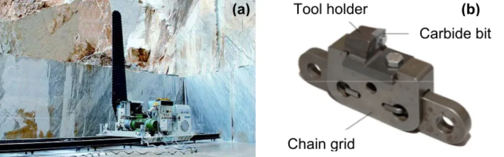
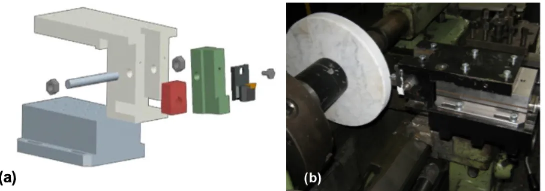
A complementary technique in stone cutting is represented by chain saw machines, especially when bottom horizontal cuts have to be operated or in case of reduced cooling fluid. In this case marble is cut by multiple carbide or PCD tools bolted on a chain which moves around an adjustable arm of 5 to 7m length (Fig. 1).
Figure 1- (a) Chain saw machine; (b) Detail of a basilar element of the chain. On a chain saw the cutting tools are abrasive inserts held by segment carried located along the rim of a chain sliding on an arm with variable length. As the chain moves along the edge of the arm each insert deepens the furrow made by the preceding one, and arm movement turns this furrow into an authentic cut-plane over which the chain continues to slide, digging further into the rock. The segments, which come in a wide range of types, are mounted on the chain in a very precise sequence and layout, chosen on the basis of the material to be cut and on the conditions that exist, case by case. Figure 3 illustrates a typical cut cross-section.
Even if the use of this type of machines is rapidly growing the choice of technical parameters (e.g. cutting speed, feed rate, depth of cut) and the influence of tool geometry on the performance of the whole process, have not been deeply investigated, up to now. At this purpose the main focus of the present research is to better understand the mechanism of material removal using single carbide tools with different rake angles. Final objective will be the optimization of tool geometry in order to obtain lower cutting forces thus reducing the specific pressure on the chain and increasing feed rates and process efficiency.
Carbide bit Tool holder
Chain grid
4.2 STONE MACHINING
Very few researches exist in literature on stone cutting. Jerro showed a mathematical approach to define and derive theoretical chipping geometries [1]. From the knowledge of the theoretical chipping geometries, chip area and mean chip thickness relations were obtained. The relationship between tangential cutting force and obtained chip thickness is empirically investigated. Brach et al. studied the problem to convert dynamometer readings of specific cutting energy into power consumed [2]. Asche et al. showed the empirical results of the influence of process parameters on tool wear [3]. Tönshoff et al. developed a model on stone cutting by disk-like diamond tools that are widely used even if it not deeply tested [4 - 5]. The model (represented in fig. 2) shows the mechanical interaction of tool and workpiece as caused by the elastic and plastic workpiece deformation of the cutting grits, the friction between stone and diamonds, stone and matrix, slurry (a mixture of marble powder and water) and matrix, figure 2. The plastic deformation and fracture deformation are influenced by the cutting conditions such as the depth of cut, tip shape of the cutting tool and the properties of the stone. When cutting stone with diamond tools, the mechanical interaction of tool and workpiece results in process forces, mainly caused by the following factors: elastic and plastic workpiece deformation by the cutting edges, friction between the stone and the matrix, friction between the slurry and the matrix. In front of a grit that is engaged in the process, stresses are affected by tangential forces. In this zone, the slurry is forced out through grooves in front and beside the grit. While the rock shows elastic characteristics up to its ultimate stresses, it is necessary for cutting edge to reach a certain minimum grinding thickness.
1) friction between slurry and matrix 4) friction between stone and grain 2) matrix erosion by slurry and chips 5) plastic deformation
3) primary chipping zone 6) elastic deformation Figure 2 - Stone chip formation during cutting [9].
diamond grain Primary chips Secondary chip STONE Ft Fc 1 2 3 4 5 6 MATRIX Crack propagation MATRIX Crack propagation Slurry diamond grain Primary chips Secondary chip STONE Ft Fc 1 2 3 4 5 6 diamond grain Primary chips Secondary chip STONE Ft Fc 1 2 3 4 5 6 MATRIX Crack propagation MATRIX Crack propagation Slurry
The material to be cut is deformed by the compressive stress conducted below the diamond. When the load is removed, an elastic reversion leads to critical tensile stresses, which cause brittle fracture. This mechanisms effected by tensile stresses is termed secondary chip formation. The general slurry is carried away by extra coolant. Factors influencing this process are directly or indirectly contained in this model: physical material properties of the stone; forces between the diamonds and the materials; stress distribution in the rock; temperatures in the tool-workpiece interface.
Konstanty presented a theoretical model of natural stone sawing by means of diamond impregnated tools for both circular and frame sawing [6]. These models seem not to have been tested by means of experiments. Pai et al. collected and observed chip samples under a scanning microscope and related them to the specific grinding energy [7]. These investigations do not try to give an organic comprehension of phenomena that happen at the interface tool-workpiece during stone cutting. Buyuksagis presented a study was undertaken to examine the effect of cutting mode on the sawing performances of some selected granites. Two cutting modes, up-cutting and down cutting, were employed in the experiments [8]. Turchetta et al. presented a study of the use of CVD diamond inserts in a chain saw, instead of traditional tungsten carbide inserts. It aims to study if a CVD inserts allows a faster cutting speed and a longer life of the tool, compared to the tungsten carbide insert does [9].
As far as the use of single cutters is concerned, Dagrain et al. [10] performed tests by using rectangular tools whose effects on the stone can be modelled as two independent processes: pure cutting and frictional contact at the interface. Authors suggested the existence of a 3D effect (linked to the cutter geometry) which affects the magnitude of the energy required to cut a unit volume of rock.
4.3 EXPERIMENTAL SET-UP
Experiments performed in this study aimed at investigating the mechanism of material removal using single carbide tools with different rake angles. In this way it may be possible to assess a better proficiency of the chain-saw machine by reducing the forces exerted during the cutting operations.
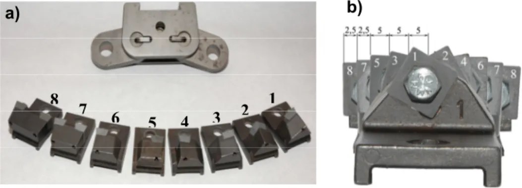
Figure 3 - a) tools and chain link ; b) profile of a complete set and values of the cutting edges active part.
8
7
6
5
4
3
2
1
The chain analyzed in this paper is composed by multiple series of eight basilar tools (showed in fig.3.a) whose envelope generates the typical profile represented in fig.3.b. The groove shape in the stone is then obtained by the superposition of the effects of the eight carbide tips: tool 1 and its symmetric 2 firstly engrave the stone creating a V shape which is progressively widen by tools 3-4 and 5-6 (each couple is symmetric with respect to the vertical axis of the profile). Tools 7 and 8 are characterized by two carbide bits working on both side of the cross section and give the final width of the machined groove.
First objective of the present research was then to simplify the analysis of such a complex material removal mechanism by means of some preliminary considerations based on the common use of the sawing machine.
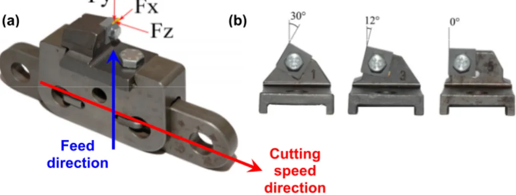
The force exerted on the carbide tip during the cutting depends then on the tool geometry and can be decomposed along the three main directions (as shown in fig. 4.a) obtaining: the cutting force (Fz), the feed force (Fy) and a thrust force (Fx).
Figure 4 - a) Tool and cutting forces; b) tools analyzed in the present research 1,3, 5.
The presence of a thrust force is due to the slope of the cutting edge of the bit with respect to the feed direction (fig. 4.b). For this reason the thrust force is expected to be higher for tool number 1 than for insert number 3, while it can be retained negligible for the number 5. Moreover the symmetry between each couple of tools (1 and 2, 3 and 4, 5 and 6) ensures that the two thrust forces are exerted in opposite directions so that the chain results globally balanced along the X axis. Due to the above mentioned symmetry and to the fact that carbide bits of tools 7 and 8 do not differs from the number 5, in the present study only inserts 1,3,5 have been considered. The complex engraving action of the chain into the marble stone has been then decomposed into the analysis of the single action of inserts 1, 3 and 5. The cutting force (Fz) and the feed force (Fy) were monitored during the use of each tool while the thrust force was not taken into account. The engraving process of the stone with a single tool has been then considered as an orthogonal cutting process characterized by fixed cutting speed on the carbide edges.
At this purpose, the second step of the present research was to reproduce the linear cutting conditions conventionally adopted during quarrying operations into a reliable experimental environment. The linear cutting speed (represented by the wrapping of the chain on the adjustable arm) conventionally adopted is about
Cutting speed direction Feed direction (a) (b)
1.2m/s while the feed rate given to the adjustable arm is kept to 40mm/min. The total length of the chain is 7.5m and the cutting portion can be retained approximately 3m. Since the pitch between each insert is 100mm, normally 30 inserts are engraving the stone at the same time. It can then be supposed that 4 series of 8 tools are contemporary working. This gives a feed rate of 0.166mm/s for each single insert.
In order to have a reliable in-process monitoring of the forces, experiments have to be performed with the constant value of the cutting speed above mentioned. It was then preferred to reproduce the machining process on a lathe and the cutting motion was transferred to the workpieces (fig. 5.c). Marble disks with a 300mm diameter were then put in rotation by the spindle and each tool was joined to a Kistler 9257 B piezoelectric dynamometer, fixed onto the lathe turret. In this way possible to measure the cutting forces in stable conditions thus avoiding the transient to reach the limit value of the cutting speed. The peripheral speed of 1.2m/s, with a 300mm diameter disk, was obtained by spindle speed of about 75RPM. On the other hand, the radial feed rate was calculated to be 0.124mm/rev.
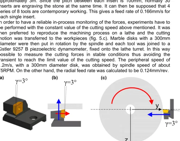
Figure 5 - a) tool and rake angle ; b) linear cutting (cutting speed in red, feed in blue); c) cutting conditions on a lathe (cutting speed in red, feed in blue).
In normal cutting conditions, tools are designed to use a rake angle γ =3°, as shown in fig.5.a and 5.b. This conventional configuration was firstly tested at fixed cutting parameters.
As far as the depth of cut is concerned, the adopted values are those described in fig. 3.b. This means that forces exerted during tests have been obtained by the same portion of the cutting edge of the conventional quarrying operations. In the present case study a depth of cut of 5mm was then adopted for all the three inserts tested.
As final step the experiments set-up, an especial device (shown in fig. 6.a and 4.b) was designed to vary the slope of the tools with respect to the y axis thus modifying the value of the rake angle γ. This effect was obtained by interposing 5 different wedge-shaped parts (in red in Fig. 6.a) between the tool holder and its support. In this way it was possible to obtain 5 values of the rake angle γ: -8°, -5°, 0°, 3°, 8°.
γ=3°
γ=3°
γ=3°
z
y
(a) (b) (c)Figure 6 - a) exploded view of the mechanical device ; b) view of the working area. It can be seen that the previous range accounts only one increase from the standard condition of γ =3°, while in the other cases the rake angle must be reduced. This was based on the fact that the engraving with a single carbide bit is retained to be much more linked to brittle fracture than to plastic deformation. Firstly the rock shows elastic behaviour up to its ultimate stresses and makes it necessary to reach a certain minimum compressive stress to assure grit penetration. When the load is suddenly removed, an elastic reversion leads to critical tensile stresses, which cause brittle fracture inducing the so called “secondary chip formation”. For this reason, the main idea of the present research is to increase the compressive action on the stone by a reduction of the rake angle. Tests conditions can be then summarized as follows:
- disk diameters 300mm; - Vc=75RPM; - f=0.124mm/rev; - depth of cut= 5mm - γ in the range [-8°,-5°,0°,3°,8°] - Test duration 20s.
Due to the slow spindle speed, the reduction of the disk diameter at the imposed radial feed rate can be estimated in 6mm. This value represents the 2% of the original diameter of the marble disk and the spindle speed should be increased of the same percentage to keep the cutting conditions constant. Preliminary tests performed to check the experimental set-up showed anyway that, due to the remarkable oscillations of the monitored forces, a 2% decrease in cutting speed can be retained negligible.
4.4 RESULTS AND DISCUSSION
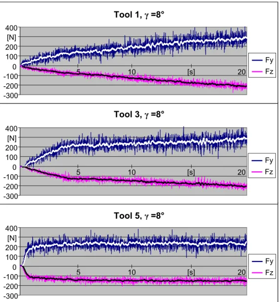
Signals acquired during the cutting have been used to obtain the charts of the cutting force (Fz) and of the feed force (Fy) depending on the testing time. Examples of the obtained results are given in fig. 7 for the three tools under analysis for a rake angle of 8°.
(b)
(a) (b)(b)
It can be noticed that for tool 1, signals acquired show a continuous increase during the test time. This is due to the slope of the carbide bit with respect to the workpiece cylindrical surface (30° as shown in fig. 4.b): during the feeding of the tool into the marble disks the active portion of the bit progressively arises thus increasing the forces exerted.
Figure 7 - Cutting force (Fz) and feed force (Fy) for the three tools; Rake angle γ =8°.
A similar behaviour is also noticeable for tool 3 even if with the use of a lower slope angle (12° in fig. 4.b) two different zones can be evidenced. A ramp up to 5 seconds represents the engaging of the tip corner, while the following quite constant plateau reflects the progressive cutting action of the right edge.
Tool 5, γ =8°
-300 -200 -100 0 100 200 400 -300 -200 -100 100 200 [N] 400 -300 -200 -100 100 200 [N] 400 [N] 0 0Tool 3, γ =8°
Tool 1, γ =8°
5 10 [s] 20 Fy Fz Fy Fz 5 10 [s] 20 5 10 [s] 20 Fy FzAs far as tool 5 is concerned, data revealed a lack of initial ramp since the cutting edge is parallel to the cylindrical surface of the marble disk and the carbide bit engraves the disk with the total depth of cut (5mm) from the beginning of the cutting action.
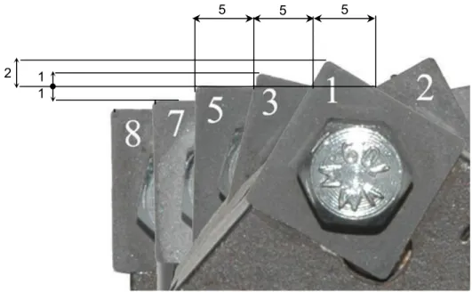
Figure 8 - Maximum radial penetrations.
Preliminary tests revealed that the main difficulty of in-process monitoring was related to the influence of disturbs during the acquisition of the cutting forces. This drawback can be related to the fact that workpieces used in the present research cannot be assumed to be constituted by a homogeneous and isotropic material. Actually the marble stone used is far from those hypotheses and may be affected by vain or internal defects which cause brittle fracture of the material hindering a continuous contact between the tool and the disk. Tools are then often exposed to vibrations whose effects are superimposed to the real variations of the signals related to the forces exerted during the cut. Data acquired in the charts were then filtered to reduce the influence of such disturbs during the monitoring processes. The obtained values are represented in colours black and white in the fig. 7, and superimposed to the acquired ones.
The effects of the rake angle variation have been investigated comparing the mean value of the filtered data acquired between 10s and 15s, using the same tool. The reason for this choice can be traced back to the geometry of the total profile of the chain: as represented in fig.6, a fixed depth of cut of 5mm at constant feed rate (0.166mm/s) results into a 2mm radial penetration for tool 1 (working time of about 12s) and a 1mm for tool 3 (working time 6s).
5 5 5
2 1 1
Moreover the signals trend is constant for tool 5 and almost constant (after 5s) for tool 3. For these reasons the mean value can be calculated, for every tool, between 10s and 15s. This procedure allowed then to estimate the mean value of the force in correspondence to the maximum radial engagement of the carbide tip. Each γ value has been tested 5 times for each tool (for a total number of 75) in order to assess repeatability of the obtained results.
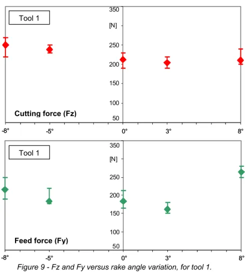
Figure 9 - Fz and Fy versus rake angle variation, for tool 1.
Results performed in the test layout can be synthesized in the following charts (fig. 9, 10 and 11): each point represents the mean value of 5 different measurements, while the dimension of error bars represents the total range of variation of the measured force (given by the difference between the highest value and the lowest). For each tool the variation of cutting force (Fz) and feed force (Fy) versus the variation of the rake angle γ, are given.
Charts in fig. 9 show that practically no reductions in cutting or feed forces are obtained for tool 1.
50 100 150 200 250 [N] 350 -8° -5° 0° 3° 8° 50 100 150 200 250 [N] 350 -8° -5° 0° 3° 8° 50 100 150 200 250 [N] 350 -8° -5° 0° 3° 8° 50 100 150 200 250 [N] 350 -8° -5° 0° 3° 8° Tool 1 Tool 1 Cutting force (Fz)
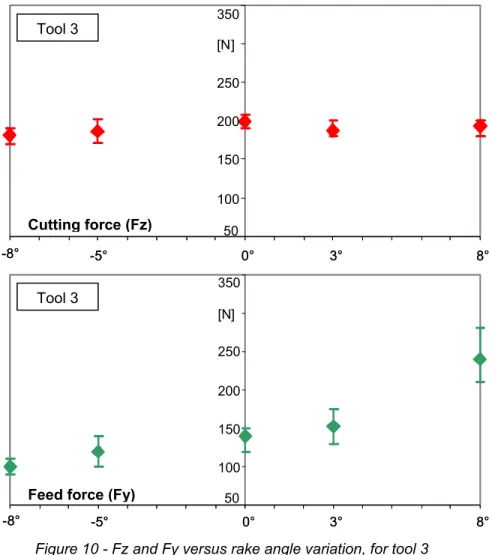
Figure 10 - Fz and Fy versus rake angle variation, for tool 3
Looking at the partial superposition of the error bars, cutting force shows only slight variations and the influence of the rake angle variation can be then retained negligible. As far as the feed force is concerned, the standard value of the rake angle (3°) seems to give the better results in terms of mean value of the monitored data.
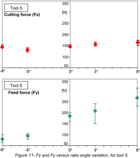
Tests performed using tool 3 (fig. 10) show that the cutting force is almost constant with respect to γ variation. Only slight reduction can be observed for the negative values of the rake angle. On the other hand, a remarkable reduction (approximately 15% to 30% of the mean value obtained with the conventional γ =3°) can be noticed in the trend of the feed force, adopting negative values of the rake angle. Phenomena described for tool 3 are much relevant for tool 5, as stated in fig. 11. As for the previous tool, cutting force seams to be not influenced by a variation of the rake angle neither positive nor negative.
-8° -5° 0° 3° 8° 50 100 150 200 250 [N] 350 50 100 150 200 250 [N] 350 -8° -5° 0° 3° 8° -8° -5° 0° 3° 8° 50 100 150 200 250 [N] 350 50 100 150 200 250 [N] 350 -8° -5° 0° 3° 8° Tool 3 Tool 3 Cutting force (Fz)
Figure 11- Fz and Fy versus rake angle variation, for tool 5.
The feed force decreases from 208N (corresponding to γ =3°) to 80N (γ =-8°). This phenomenon confirms the tendencies outlined in the state-of-the-art. The secondary chip formation mechanism seems to be facilitated by negative values of the rake angle which increase the compression of the material instead of the engraving action of the cutting edge. In the present case study the removal rate due to plastic deformation was then retained negligible respect to the one generated by brittle fracture.
A further interesting aspect denoted by the feed force graph in fig.9 is related to the reduction rate: data show that passing from γ =3° to γ =-5° a linear dependence can be established while a further reduction (γ =-8°) does not give the same effects on Fy. This is probably due to the fact that with γ =-5° represents a threshold value below which the feed force reaches a limit value of about [80-90]N.
As further verification, such results have been studied by ANOVA analysis performed on the 75 tests above exposed. The fundamental hypotheses for the
50 100 150 200 250 [N] 350 50 100 150 200 250 [N] 350 -8° -5° 0° 3° 8° -8° -5° 0° 3° 8° 50 100 150 200 250 [N] 350 50 100 150 200 250 [N] 350 -8° -5° 0° 3° 8° -8° -5° 0° 3° 8° Tool 5 Tool 5 Cutting force (Fz)
ANOVA applicability to the experimental data, that are the normality and the homogeneity of the variance of the residuals, have been firstly verified.
ANOVA analysis underlined that, as stated previously, the rake angle variation significantly influences the feed force for all the tools tested while it has only slight effects on the cutting force of tool 1.
4.5 CUTTING PRESSURES
Analyzing charts of cutting and feed forces cyclical patterns were often noted and a first visual inspection of the related marble disks, revealed an obvious principles of fracture, which are probably due to inclusions of quartz.
Figure 12 – Different types of grooves on the marble disks and measures of the amplitude of micro-cracks generated on the cutting edges of different tools.
A second phenomenon which can be derived from the above mentioned charts is that some tests showed higher values than others obtained with the same values of γ. This behaviour cannot be attributed to the non-homogeneous consistence of the stone (quartz inclusions) since non standard values have been registered for quite continuous time. It was then analyzed the possible state of wear of the cutting edge has possible influencing factor. Therefore, an analysis at optical microscope was carried out on the total number of inserts used during tests. Micro-inspection of flanks and faces of the adopted tools revealed that inserts related to higher cutting forces presented also a significant wear (figure 12). The presence of micro-cracks affecting both tool flank and in particular the tip (e.g. tool 5-1 in fig. 12) are not attributable neither to the hardness of the material nor to its lack of homogeneity
Tool 1
Tool 3
Tool 5-2
Tool 5-1
Tool 1
Tool 3
Tool 5-2
Tool 5-1
but it seems to be more related to the discontinuous cutting process. Impacts generated by intermittent contact between tool and workpiece induced cracks in the edge thus decreasing its cutting power, in despite of the positive relationship between the hardness. It can be also assumed that this particular behaviour also occurs in the cut with chain saws in the quarry.
Figure 13 – Comparison between cutting pressure monitored by the sensors and calculated values obtained following (1).
As a further study the specific pressure Ps and the index 1/n of the material have
been also estimated. Since no theory can be find in literature to determine these mechanical properties, conventional formulas adopted for the cutting of metals have been used (Kronenberg theory); theoretical values obtained for Ps may then
differ form the effective ones. Anyhow this analysis will require further study in order to use a larger number of tests. Data of cutting pressure Pt and chip cross
sections S were processed with statistical software which enabled to empirically extrapolate the specific pressure Ps and the index 1/n. At this purpose the software
needs of the equation that links the two variables:
Inserto1 seconda prova γ=3° su disco1
-100 100 300 500 700 900 1 287 573 859 1145 1431 1717 2003 2289 2575 Pt reale Pt calcolata
Inserto3 seconda prova γ=3° su disco2
-100 100 300 500 700 900 1 287 573 859 1145 1431 1717 2003 2289 2575 Pt reale Pt calcolata
Tool 1, γ=3°
Tool 3, γ=3°
Measured Pt Calculated Pt Measured Pt Calculated Pt [MPa] [MPa] [s] [s] 5 10 20 [s] 5 10 20Inserto1 seconda prova γ=3° su disco1
-100 100 300 500 700 900 1 287 573 859 1145 1431 1717 2003 2289 2575 Pt reale Pt calcolata
Inserto3 seconda prova γ=3° su disco2
-100 100 300 500 700 900 1 287 573 859 1145 1431 1717 2003 2289 2575 Pt reale Pt calcolata
Tool 1, γ=3°
Tool 3, γ=3°
Measured Pt Calculated Pt Measured Pt Calculated Pt Measured Pt Calculated Pt Measured Pt Calculated Pt [MPa] [MPa] [s] [s] [s] 5 10 20 [s] 5 10 20n s t
P
S
P
1 −⋅
=
(1)being Ps (specific pressure) and -1/n (Kronenberg index) the extrapolated indexes.
Ps was extimated between 320N/mm2 and 346N/mm2, while the index 1/n ranged
between 0.263 and 0.308. The Kronenberg index identifies the material to be cut, so it should be a nearly constant value. The variation is therefore due primarily to the non-homogeneity of the material. On the other hand, the specific pressure depends on the material but also on tool geometry; in this case variations of the obtained values can be then justified in the use of tools 1,3 and 5.
A more rigorous calculation of Ps is then desirable for a future development of this
topic. It should require the use of feed rates and depths of cut giving a chip cross section of 1mm2 in order to retain Ps equal to Fz.
Data of cutting pressure derived from the above mentioned formulas (reported in black in fig. 13) fitted to the experimental values obtained by the dynamometer and have been then retained acceptable in the intermediate part of the cutting process. This zone is, in fact, the only part of the acquired charts which is not interested by the non-linear and unsteady phenomena revealed by the piezo-cristals during the first contact between tool and marble disks.
4.6 CONCLUSION
Experience revealed a reduction of about 50% in feed force passing from the standard value of rake angle (γ=3°) to γ= -8°, while cutting force showed only slight variations. This phenomenon has been traced back to the secondary chip formation mechanism which is increased by the higher tendency of the carbide bit to compress the marble, using negative values of the rake angle. The plastic deformation is then restricted to an extremely thin layer of material and the conventional theory of chip formation under shear stresses cannot fit to this particular case study.
As final conclusion, it is advisable to use tools 3, 5 and their symmetrical 4 and 6 with negative rake angle of γ =[-5,-8]°. This is also confirmed by the fact that tools 7 and 8 have similar geometry to 5: it can be assumed that even for these a negative rake angle should offer better performances in terms of feed force reduction. In view of possible improvements on the overall performance of the machine that uses these types of carbide bits, negative values of γ can provide a reduction of the feed resistance above 20%, without producing any significant variation on the main cutting force. The same enhancement is then expected in terms of power saving since less energy is needed to feed the adjustable arm in the stone.
In these conditions, with reduced feed resistance, the feed rate could be increased thus improving the productivity of the machine. Anyway this type of machine improvement must be compatible with the permissible limit solicitations of the chain. Furthermore, using a negative value of the rake angle γ a reduced clearance angle α can be tolerated giving a higher resistance section of the carbide bits, thus strengthening the global tool.
4.7 REFERENCES
[1] Jerro, H.D., Pamg, S.S., Yang, C., Mirshams, R.A., Kinematics analysis of the chipping process using the circular diamond saw blade, Transactions of ASME: Journal of Manufacturing Science and Engineering, vol. 121, pp. 257-264, May 1999.
[2] Brach, K., Pai, D.M., Ratterman, E., Shaw, M.C., Grinding forces and energy, Transactions of the ASME: Journal of Engineering for Industry, Vol. 110, pp. 25-31, February 1988.
[3] Asche, J., Tönshoff, H.K., Friemuth, T., Cutting Principles, wear and applications of diamond tools in the stone and civil engineering industry", Proceedings of Diamond tools Conference, pp. 151-157, 1999.
[4] Tönshoff, H.K., Warnecke, G., Research on stone sawing, Advances in Ultrahard Materials Applications Technology, P. Daniel, Hornbeam, ed. England, Vol. 1, pp. 36-29, 1982.
[5] Tönshoff H. K., H. Hillmann-Apman, J. Asce, 2002, Diamond tools in stone and civil engineering industry: cutting principles, wear and applications, Diamond and related materials, Vol. 11, pp. 736-741.
[6] Konstanty J., Theoretical analysis of stone sawing with diamonds, Journal of Materials Processing Technology, 123, pp. 146-154, 2002.
[7] Pai, D.M., Ratterman, E., Shaw, M.C., Grinding swarf, Wear, vol. 131, pp. 329-339, 1989.
[8] Buyuksagis I.S., Effect of cutting mode on the sawability of granites using segmented circular diamond sawblade, Journal of Materials Processing Technology 183 (2007), pp. 399–406.
[9] Turchetta S., Carrino L., Polini W., CVD diamond insert in stone cutting, Diamond and related materials, vol. 14, 2005, pp. 641-645.
[10] Dagrain F., Detournay E., Richard T., Influence of cutter geometry in rock Cutting, Proceedings of th 38th U.S. Rock Mechanics Symposium, Washington DC July 2001,vol. 2, pp. 927-933. Lisse, The Netherlands: Balkema, 2001.