State of the art (SOTA) analysis
To summarise the main characteristics and the basic information regarding handover process in the main different radio access systems (HO) concepts, this chapter shows analysis and conclusions resulting of investigation on handover concepts/mechanisms/solutions in the following main areas:Cellular wide area networks including 2G (second generation) and 3G (third generation)
Wireless networks in the area of IEEE 802 Family IETF solutions
For each radio access system/technology a possible outline could be present and contain the following information with focus on handover mechanism on user/control plane:
Concepts for handover
o Location model, e.g.: mobility state, Location Area (LA), Routing Area (RA), IP address and main identifiers (TIMSI, Cell ID, LAI for GSM, IP address).
o Handover reference model; entities and functions involved in handover process and their roles at a higher level. Example for GSM - Mobile station (MS) is: state (active); taking radio measurements; radio access network; performing radio measurements; traffic load measurements; applying decision criteria; commanding the handover; applying handover
triggering based on radio quality, received power, load sharing, etc.
Main steps (high level) in the handover sequence and protocols. Example for GPRS: MS decides cell reselection, camps on new cell, gets new PSI, asks for radio link layer.
Specific mechanisms on user plane. Example: for UMTS: soft/softer handover; for IP: packet duplication/tunnelling/forwarding.
Specific mechanisms on control plane: e.g. context aware protocols as NACC (Network Assisted Cell Change), or IETF CARD (Candidate Access Router Discovery) for GPRS.
Inter-RAT (Radio Access Technology), Inter-domain (Administrative domain) handover.
Issues during handover events (control signalling, “black times”).
1.1. Cellular wide area networks
This section provides an overview of the handover concepts in cellular wide area networks on the second (2G) and third generation (3G).
1.1.1. GSM/GPRS/EDGE
The GSM/(E)GPRS [1] mobility management is strictly related to the network architecture/layout location information associated to a single cell and groups of cells, i.e. LA for CS (Circuit Switched) domain and RA for PS
(Packet Switched) domain. Mobility Management (MM) has basically a two-level structure:
When the MS is attached to the network, but it has no communication context with the network (Idle Mode for GSM and Standby State for GPRS), cell reselection is done by the MS locally according standardised algorithms, and only changes/updating of LA (for GSM) and RA (for GPRS) are communicated to the network.
When the MS has a communication context with the network (Ready State for the GPRS and RR - Radio Resource - Mode for GSM), the network knows the location at cell level, even if the GSM and GPRS mobility management algorithms are different.
1.1.1.1. Handover in CS Domain
Handover is initiated by the network based on radio subsystem criteria (RF - Radio Frequency - level, quality, distance) as well as network directed criteria (e.g. current traffic loading per cell, maintenance requests, etc.). Radio subsystem criteria derives from measurements done by the MS and BTS (Base Transceiver Station) and delivered to BSC (Base Station Controller).
Handover procedures are designed according the hierarchical structure of the GSM networks and can be classified (see also Figure 1) according to internal HO (i.e. intra cell/intra BSC HO) and external HO (i.e. inter BSC/MSC - Mobile Switching Center - HO). For internal handover, BSC is supervising the handover procedure, while for external handover, MSC(s) is (are)
supervising it. In any case, BSC initiates the handover procedure, even if for network criteria a trigger could be sent from MSC.
Figure 1: Network Hierarchy and Handover types in GSM
To cope with the stringent interruption time requirements (100 ms - 150 ms), handover procedures are quite complex for the amount messages and system elements involved [2]. Cell reselection procedure involves mainly the MS and BSS for Internal HO, and MS, BSS (Base Station System) and MSC(s) for external HO, while location procedure has its own identifier. At the high level, handover process consists of the following main steps:
Detection of handover condition by the BSS and the selection of the new cell/channel (target cell/target channel). In case of valid multiple handover conditions are met, prioritization is applied.
Allocation of new radio channel and network resources (i.e. inter-MSC channels for inter-MSC handover) for the target cell.
Information to MS about the target channel/cell.
Access procedures by the MS on the new channel (plus synchronization procedures for not synchronized cells).
1.1.1.1.1. Specific mechanisms for HO
Control plane: the stringent target of interruption time is met by means of a resource pre-allocation scheme and complex signalling handover procedures. Besides, HO algorithms consider thresholds and status info to avoid ping-pong effects. An additional feature, complementary to handover, which uses handover mechanisms, is the “direct retry”, applied e.g. at the call set-up when there are no radio resources available in the target cell.
User plane: there are not radio user plane specific features, while optimizations are applied in the MSC/BSS.
Main handover issues are: signalling load, frames-loss during interruption time, no inter-administrative domain handover allowed.
1.1.1.2. Cell reselection for MS in Ready State in PS domain - (E)GPRS
In case of (E)GPRS, for MS in Ready State the cell reselection is decided by MS by using standardized criteria/algorithms [3], which utilise MS measurements of received power of serving/neighbours cells and network info (i.e. the specific parameters for each cell). Optionally, cell reselection can be decided by the network and the decision about where re-selection will take place is communicated to MSs via PSI (Packet System Information). Cell reselection procedure involves mainly the MS and the BSS and the mobile is identified by the TLLI (Temporary Logical Link Identity). For “normal MS control” main steps are the following ones:
1. MS detects cell re-selection condition and selects the new cell based on received level measurements done by the MS and parameters sent from the devices.
2. If the MS is in Packet Transfer Mode, then the TBF (Temporary Block Flow) communication context has been created with the BSS and the radio resources have been allocated. In this case, MS could decide to interrupt the TBF.
3. The MS camps on the new cell and it listens broadcast control channels to receive PSI.
4. As soon as mandatory PSI are received, the mobile sends a frame to the BSS, the latter will add cell identifiers and will forward it to core network. Then SGSN (Serving GPRS Support Node) will inform the BSS about old cell and forward further frames towards the MS to the new cell.
5. If the TBF was interrupted, then MS starts a new TBF with the new cells.
This procedure is quite simple and it minimises control messages, but the interruption time is quite high, in particular to receive the new PSI (step 3). To minimise the service interruption time, NACC (Network Assisted Cell Change) has been adopted. In this way, when cell reselection condition has been detected, before to leave the old cell, MS requires to the network PSI information of the target cell. When this information is received, it camps on the new cell and it asks for missing PSI. With NACC, service interruption time decreases to about 1 sec.
1.1.1.2.1. Specific mechanisms for HO
User plane: during cell reselection, frames waiting to be transmitted downlink to the MS in the old cell, could be forwarded in the target cell for transmission.
The control plane: HO combined procedures (CS/PS domains) are possible; NACC could be considered as network related context transfer function.
Cell reselection issues (Packet Transfer Mode) [4]: possible downlink frames-loss during interruption time; long interruption time.
1.1.2. 3GPP UMTS WCDMA
UMTS mobility management is performed at different levels. The similarities with GSM are many, since the two systems have similar RAN (Radio Access Network) architecture and practically the same CN (Core Network) architecture. The location of the UE (User Equipment) is known at either: cell level, URA (UTRAN Registration Area) level, a group of cells as seen from the S-RNC, LA/RA level, a group of cells as seen from the CN, LA for CS domain, RA for PS domain.
One of the main differences with GSM is that in UMTS the distinction of CS and PS is made only above the RNC, but not in the UTRAN. This means that theoretically, all UTRAN transport channels can be used for communications towards both MSC and SGSN.
UMTS has an Idle Mode that is inherited from GSM: the UE is registered to the network (therefore being known to the CN), no communication context exists, cell reselection is done by the UE, and only changes/updates of LA (for CS) and RA (for PS) are communicated to the network.
The UE can otherwise have a RRC (Radio Resource Control) connection established with an S-RNC (Serving Radio Network Controller), therefore being known to UTRAN, in which case different options exist regarding MM within UTRAN.
The UE can remain idle within a URA (RRC state: URA_PCH), in which case it can:
inform the S-RNC when the URA is changed be paged by the S-RNC within the URA
start an uplink activity (after changing RRC state).
The UE can remain idle within a cell (RRC state: CELL_PCH), in which case it can:
inform the S-RNC when the cell is changed be paged by the S-RNC within the cell
start an uplink activity (after changing RRC state).
The UE can be in an active communication state for the MM under which is the responsibility of the UE, that will perform Cell Update when mobility implies the need to perform cell changes (this is the usual behaviour in RRC state CELL_FACH).
The UE can be in an active communication state for the MM under which is the responsibility of the UTRAN, that will decide on handover (channel reconfiguration, handover messages, etc.) when mobility implies the need to perform cell changes (this happens in RRC state CELL_DCH).
1.1.2.1 Handover
Handover is a network controlled type of change of cell, that for UMTS can e performed for both CS and PS domains. It is initiated by the network b
based on radio subsystem criteria (RF level, quality, distance) as well as network directed criteria (e.g. current traffic loading per cell, maintenance requests, etc.). Radio subsystem criteria are driven by measurements of the UE/NodeB and delivered to RNC. Handover could be classified in the following list, with respect to the architecture:
Intra cell
Inter-cell/ intra-NodeB Inter-NodeB/ Intra-RNC
Inter-RNC (with Iur streamlining) Inter-RNC (without Iur streamlining)
Intra-MSC Intra-SGSN Inter-MSC Inter-SGSN
Th e catego dover, which lea t nt
handover procedures and characteristics:
er are the following ries of han d o differe
Hard Handover: all the old radio links in the UE are removed before the new radio links are established. Hard HO can be seamless or non-seamless. Seamless hard HO means that the HO is not perceptible to the user. A HO that requires a change of the carrier frequency (inter-frequency handover) is always performed as hard HO.
N. Soft HO is Soft Handover: the radio links are added and removed in a way that the UE always keeps at least one radio link to the UTRA
performed by means of macro diversity, which refers to the condition that several radio links are active at the same time. Normally soft HO takes place between cells operating on the same frequency.
site of
co-Anoth Acces
Softer handover: a special case of soft HO where the radio links that are added and removed belong to the same Node B (i.e. the
located base stations from which several sector-cells are served). In softer HO, macro diversity with maximum ratio combining can be performed in the Node B, whereas generally in soft HO on the downlink, macro diversity with selection combining is applied.
er classification can consider more issues related to the different Radio s Technologies and UTRAN modes as follows:
Handover 3G -3G (i.e. between UMTS and other 3G systems) FDD soft/softer handover FDD inter-frequency hard handover FDD/TDD handover (change of cell) TDD/FDD handover (change of cell) TDD/TDD handover Handover 3G - 2G (e.g. handover to GSM) Th a r HO are on r UMTS FD
The m us cause for perform he a user, due to its er
efined by the 3 following sets of cells: Handover 2G - 3G (e.g. handover from GSM)
e c ses of Soft and Softe ost obvio
ly available fo D mode. ing a handover is w n
movement, can be served in another cell more efficiently (e.g., less pow emission, less interference). However it could be also performed for other reasons, such as system load control.
The relationship between the UE and the cells that could provide communication means for the UE is d
Active Set is defined as the set of Node-Bs the UE is simultaneously connected to (i.e. the UTRA cells currently assigning a downlink DPCH to the UE constitute the active set).
d Set.
The cells not included in the active set, but included in the CELL_INFO_LIST, belong to the Monitore
Cells detected by the UE, which are neither in the CELL_INFO_LIST nor in the active set, belong to the Detected Set. Reporting of
For ha
measu over decision. The
measurements of the detected set is only applicable to intra-frequency measurements made by UEs in CELL_DCH state.
ndover, the UE assumes a fundamental role in delivering a number of rements to the network, that will be used for hand
different types of air interface measurements are:
Intra-frequency measurements: measurements on downlink physical channels at the same frequency as the active set.
Inter-frequency measurements: measurements on downlink physical channels at frequencies that differ from the frequency of the active set. Inter-RAT measurements: measurements on downlink physical
channels belonging to another radio access technology than UTRAN, e.g. GSM.
Traffic volume measurements: measurements on uplink traffic volume.
Quality measurements: measurements of downlink quality parameters, e.g. downlink transport block error rate
UE-internal measurements: measurements of UE transmission power and UE received signal level.
UE positioning measurements: measurements of UE position.
It follows a list of cell relation information that can be used for HO decision: HCS (Hierarchical Cell Structure) priority: it’s a cell priority level
reselection.
Antenna co-location indicator: to indicate whether the neighbouring cell’s antenna is collocated with the current cell’s antenna.
icator
Coverage ind : to indicate whether the neighbouring cell overlaps,
The U each one is
co o
Hando effect, multi-administrative
ll reselection
ell reselection is a UE controlled type of change of cell, that for UMTS can retically for both CS and PS domains. In practice, ell Reselection is performed only for services in the PS domain without
covers or is contained in the current cell.
E supports several measurements running in parallel and ntr lled and reported independently of every other measurements.
ver issues are: signalling load, ping-pong domains.
1.1.2.2. Ce
C
be performed at least theo C
stringent requirements on service interruption. Cell Reselection is only performed by the UE in the RRC CELL_FACH state, utilising UE measurements of the received power of serving/neighbours cells and network info (i.e., parameters specific for each cell). There exists an HCS (Hierarchical Cell Structure) priority that is provided to the UE, consisting in a cell priority level (0…7) that can be considered by the UE when performing cell reselection.
Cell reselection issues (packet transfer mode) are: interruption time, signalling load, ping-pong effect, multi-administrative domains.
1.2. Wireless local/short-range networks
eless networks.
IEEE 802.11 / Wi-Fi
diagram of the WLAN architecture. It follows an overview of the most widespread types of wir
1.2.1.
Figure 2 presents a simplified block
L2 Distribution network User WLAN terminal WLAN terminal WLAN AP WLAN AP Access router Local services Access router DNS DHCP AAA Server/ proxy Billing system L2 Distribution network IP Backbone network HTTP server Gateway NAPT DB Other WLAN AP Network management WLAN radio interface AAA roaming IP interface
Figure 2: simplified block diagram of the WLAN architecture
Link and PHY layer events for handover
), it has to switch into romiscuous mode to discover and to initiate a connection with a new AP 1.2.1.1.
When a MN moves between two Access Points (AP p
[5]. For discovering the target AP in a WLAN that does not support RSNA (Robust Secure Network Association), three different steps are required for the MN in order that it may associate with an AP.
1. First the MN evaluates the potential APs in its range (radio signal or energy strength).
2. In active mode, the MN scans its default channel to identify the available APs (exchange of Probe Request and Probe Response). If
3.
s. On
phase b ication Request/Response). The reception
ayer interprets this as
2.
d. In case of handover it will be
These e
is managed by the link-layer protocols and as long as the MN is on the same
hanged. However the mobile the MN does not receive any response from AP (e.g. no APs are operating in this channel), the MN switches to the next channel and continues the scanning.
In passive mode, the MN only listens to beacons sent by AP to discover the potential AP
ce the MN discovers its target AP and its parameters, an authentication egins (exchange of Authent
of a (Re-) Association Response that completes a successful association conveys that the MN point of attachment to the network may have changed. Events to and from the network layer for handover are:
1. Link-up trigger:when a new link is created this trigger is provided asynchronously to the network layer and the IP l
a possible configuration change.
Link-down trigger: is provided asynchronously to the network layer when a link instance is remove
followed by a link-up trigger.
vents are mostly located at the mobile node. This roaming operation
subnet. Note that no L3 signalling takes place.
A (Re-) Association Response from the AP to the MN conveys that the MN point of attachment to the network may have c
Request/Response is the information that is exchanged between the AP and the MN.
In a RSN, data packets between the MN and the AP are allowed upon
1.2.2. IEEE 802.16 / Wi-Max
ee Figure 2 for the simplified block diagram of the WLAN architecture [6].
1.2.3. IEEE 802.21 (Multi Radio technology Wi-Fi/Wi-Max)
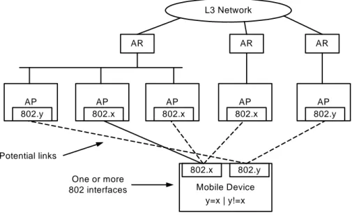
n architectural framework [7] is illustrated by the following figure:
successful completion of a 4-way handshake. In this case, the reception of a (Re-) Association Response does not imply the link is established yet.
S
The BS stack in 802.16e has changed in comparison to the basic 802.16a in which a Mobility Agent (MA) has been added on top of the convergence layer. Some of the above presented triggers are passed to and from this MA through the CS SAP (Convergence Sublayer - Service Access Point) as in other 802.1x family. Other triggers are sent to and from the MSS via the PHY and the MSS and BS receive them on their respective MAC layers.
Mobile Device 802.x 802.y y=x | y!=x One or more 802 interfaces AP 802.x AP 802.x AP 802.x AP 802.y AR L3 Network AR AR AP 802.y Potential links
Figure 3: framework of the IEEE 802.21 architecture
The main objective of 802.21 is to provide a standard to support mobility and handovers not only within 802.x networks of a certain type (e.g. 802.11), but also between different types of 802.x networks (e.g. between 802.11 and 802.16), and handovers involving non-802.x types of networks (e.g. between 802.11 and cellular networks). The problems addressed include:
Detection of Network Attachment (DNA) and support for optimised network selection.
Handover optimization:
o Definition of handover information and transport of such information over the link.
o Provision of L2 Triggers to upper layers: so the L3 can make optimised handover decisions.
1.2.3.1. Detection of Network Attachment (DNA)
It was proposed to reuse the Controlled/Uncontrolled Port Entity (CUPE) model derived from 802.1x, securing the Handoffs Information Base on the node. In addition, a media-independent protocol for transmission of information is required. Such information includes handover info, network detection info, network selection info, event info, info for backhaul DNA signalling (i.e. gathering handover information from candidate AP through current AP), and so forth. The information might be useful for an authentication decision, to indicate a subnet crossing, the L3 services provided at this AP, neighbourhood lists, vendors, operators, and so forth.
1.2.3.2. L2 Triggers
Triggers [8] can arrive from different parts of the layer (e.g. PHY, MAC) and from the same node or from a remote node (i.e. the mobile node or the base station). Thus, triggers must carry an identification of where they come from, i.e. the layer and the node. Furthermore, an L3 entity must register with the L2 to receive triggers that it is interested in and understands. The L3 entities considers the triggers as advisory of nature and not mandatory, and might take a more defensive approach when the triggers originated remotely or when the authenticity of the trigger cannot be assured. Security, reliability and robustness of the trigger mechanism is naturally important.
Some triggers that have state-bounded time information need to be assigned an identifier of the discrete event conveyed by the trigger itself. Then other triggers easily can use this identifier to refer to the discrete event.
Triggers can be of type "event" or "predictive". Predictive triggers carry predictive information, such as the time bound of the expected occurrence of
the event and the level of confidence that the event will take place. To support and optimise the handover process, the following triggers might be useful: Link_Up, Link_Down, Link_Quality_Crosses_Threshold, Link_Going_Down (predictive), Link_Going_Up (predictive) Trigger_Rollback and Better_Signal_Quality_AP_Available.
1.2.4
Handover decision logic in wireless networks
In Wi-Fi, for L3 handovers the sole existence of the link-up after a link down trigger is used as logic to recognize that a handover has taken place. The mobile terminal makes the decision to perform an handover.
In Wi-Max, the logic for handover in 802.16e is based on the PHY layer parameters of the MSS. In network initiated HO the congestion in a cell is used also as a parameter to request the MSS to HO to another cell.
Given that different 802 network types follow different rules to make the handover decisions, 802.21 does not mandate a decision logic, but provides a toolbox (e.g. in terms of DNA, triggers, etc.) to optimise and improve the handover decision process of L2 and/or L3.
1.2.5
Consequences of a handover
In WI-Fi and in Wi-Max, from the point of view of MAC layer, the data rate can be reduced to other users in the same BSS (Base Station Subsystem) or ESS (Extended Service Set) due to an increase in the time for the contention window setup by the AP to allow for transmission, mostly due to collisions of user’s packets.
802.21 facilitates easier handovers between different types of network technologies. By accommodating handovers between diverse networks of different types, the consequences of the HO may be more dramatic. For example, a HO between a private 802.11 WLAN and a public Cellular GSM may result in dramatic changes in terms of different characteristics, different administrative policies, different performances, different pricing., etc.
1.3. IETF WGs and related protocols
This section provides an overview of the handover concepts in IETF WGs.
1.3.1. MIPv4 Architecture
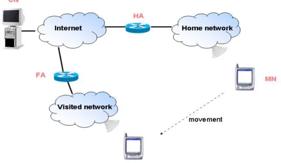
Figure 4 presents a framework of the MIPv4 architecture [9]. While away from its home subnet, a mobile node (MN) is registered with a Home Agent (HA) that is residing on the MN’s home subnet. The HA receives the traffic destined for MN globally routable home IP address (normally by using Gratuitous ARP and Proxy ARP), and tunnels the traffic to the Care-of-Address (CoA) that the MN has registered with the HA. To save the scarce IP address space, MIPv4 is normally implemented with Foreign Agent (FA). A FA is an access router (AR) with MIPv4 functionality, and it offers a globally routable CoA that can be shared by all MNs on that subnet. The HA tunnels packets to the FA, which decapsulates them and forwards them to the MN’s new link. In this way the MN uses the CoA, a topologically correct address on the new link, but this address is hidden to the opened upper layer connections.
The MIPv4 specification also allows for co-located mode (similar to MIPv6), in which there is not need for FAs, because the MN obtains its own co-located CoA on the new link (e.g. by means of DHCP), registers (binding) to its HA the CoA with its HoA, and takes care of packets decapsulation arriving from the HA (in this case the tunnel ends to the MN). The MN must manage two addresses during communication: the HoA and the CoA.
Figure 4: framework of the MIPv4 architecture
1.3.1.1. Network layer detection of Access Routers
To allow for network layer movement detection, the FA transmits periodically Agent Advertisements (i.e. an ICMP Router Advertisements with a MIPv4 extension) on the access network. Upon reception of an Agent Advertisement (AA) originating from a FA with an unknown FA address, the MN detects that it has moved to - or has come within range of - a new FA.
The AA also provides further information necessary for a possible subsequent handover. To restrict the resource consumption of AAs, the MIPv4 standard mandates that the rate of transmitted AAs is limited. To speed up the detection process, however, MNs are allowed to send Agent Solicitations (AS), which triggers FAs to respond with an AA.
On some types of wireless links, the network layer detection of access routers can also be triggered by lower layer events. For example: when the MN link layer detects that it has come within range of a new access point, this event may trigger the MN network layer to transmit an AS to detect if possibly a new access router is connected to (or co-located with) the new access point. Likewise: when a link-layer AP detects that a new MN has connected to it, this event may trigger an interconnected (or co-located) AR to respond with an AA. Periodically transmitted unsolicited AAs are normally not sent on such networks.
1.3.2. MIPv6 Architecture
See Figure 5 for a framework of the MIPv6 architecture [10].
While away from its home subnet, a MN is registered with its HA, that is residing on the MN’s home subnet. A CN can communicate to the MN by using the MN’s HoA. The HA receives the traffic destined for MN by using the Proxy Neighbour Discovery procedure instead of ARP in MIPv4: so, there is not a dependence by the particular under data-link layer. The HA tunnels the traffic to the CoA, a temporary IPv6 address related to the actual MN’s location. At the same time, a MN has a static address (HoA) valid on its own home network and one (or more) temporary address (CoA) valid on
the visited network. Only a CoA is registered to the HA in a certain time: this is the primary CoA.
Figure 5: framework of the MIPv6 architecture
Unlike MIPv4, there is not the necessity to save the scarce IP address space, so FAs are not needed and MIPv6 is analogous to the use of MIPv4 in co-located mode. The MN obtains a CoA on the new link by means stateless address auto-configuration or alternatively stateful (DHCPv6); then it sends a binding update (BU) to its HA to register the just formed CoA, binding HoA and CoA. The HA responds to it sending an ACK, to confirm the registration, that is the binding HoA/CoA. In MIPv6 the Route Optimisation (RO) is native, instead of MIPv4. After the first packet is received from a CN, the MN could initiate the correspondent binding procedure, sending a BU to the CN to inform it that it’s reachable directly (without passing via
the HA). Now, the CN sends packets directly to the MN, using the IPv6 Routing Header and not a tunnel as is MIPv4, reducing the overhead related to the encapsulation. The MN and its HA belong to the same administrative domain, so these can easily perform a security association by using IPSec features. Prior to sending a BU to the CN, the MN initiates a Return
Routability test to ensure "no-less security" of the BU. A first message is sent
directly to the CN, while another is sent securely to HA which relays it to the CN. The CN responds to each of these messages with a cookie (or a node key, or a token and by using also cryptographic algorithms): i.e. one cookie is sent directly to the MN, while the other is relayed via the HA (and the secure tunnel between the HA and the MN). MN forms a key from the two cookies. By authenticating correctly the BU with derived key (binding management key), the MN proves to the CN that it has passed the Return Routability test.
1.3.2.1. Network layer detection of Access Routers with MIPv6
MIPv6 bases its network layer movement detection algorithm on the Neighbour Discovery (ND) features of IPv6, which includes Router Discovery and Neighbor Unreachability Detection. Upon reception of a Router Advertisement (RA) originating from an AR with an unknown AR address, the MN detects that it has moved to - or has come within range of - a new AR. The RA also provides further information necessary for a possible subsequent handover.
To restrict the resource consumption of RAs, the ND specification mandates that the rate of transmitted RAs is limited. To speed up the detection process, however, MIPv6 relaxes the rate limitation on unsolicited RAs. The MN is
also permitted to send Router Solicitations (RSs), which trigger ARs to respond with a RA.
On some types of wireless links, the network layer detection of ARs can be triggered by lower layer events. For example: when the MN link layer detects that it has come within range of a new AP, this event may trigger the MN network layer to transmit a RS to detect if possibly a new AR is connected to (or co-located with) the new AP. Likewise: when a link-layer AP detects that a new MN has connected to it, this event may trigger an interconnected (or co-located) AR to respond with an RA. Unsolicited RAs are normally not sent on such networks.
1.3.3. Seamless mobility with Hierarchical MIPv6 (HMIP)
Hierarchical MIPv6 (HMIP) [11] is currently a concept belonging to IETF internet drafts. To reduce signalling delay and network overhead, HMIP installs a Mobility Anchor Point (MAP) above one or more ARs for an access network. Basically, the MAP functions as a FA for the visited network, the local MAP’s domain. The MN uses a Regional Care of Address (RCoA), valid for that local MAP’s domain, as a CoA, when it registers itself at its HA/CN(s). Hence, the MN can move within the local MAP’s domain, passing through possible several APs and/or ARs, and keeping reachability solely by registering its movement through different local IP addresses, called on-Link Care of Address (LCoA), with the MAP, by means of sending Binding Updates for couple of addresses RCoA/LCoA. The HA/CN may not be aware of the local movement of the MN, thus:
reducing the network messaging overhead caused by mobility, especially in those cases where MN and HA/CN(s) are far away;
improving handover performances by resolving mobility issues locally in the visited network.
HMIPv6 concepts are an extension to the MIPv6 protocol: a HMIPv6-aware MN with an implementation of MIPv6 should choose to use the MAP, when discovering such capability in a visited network. However, in some cases the MN may prefer to simply use the standard MIPv6 implementation, for instance, when the MN is located in a visited network within its home site: in this case, the HA is located near the visited network and could be used instead of a MAP.
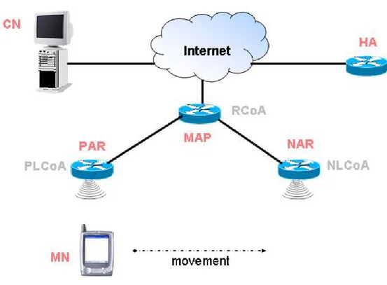
The network architecture shown in Figure 6 illustrates an example of the use of the MAP in a visited network. In this figure, MAP can help in providing seamless mobility for the MN as it moves from the Previous Access Router (PAR) to the New Access Router (NAR), while communicating with the CN. A multi-level hierarchy is not required for a higher handover performance, hence it is sufficient to locate one or more MAPs (possibly covering the same domain) at any position in the operator's network.
To use the network bandwidth in a more efficient manner, a MN may decide to register with more than one MAP simultaneously and use each MAP’s address for a specific group of CNs.
Figure 6: Hierarchical Mobile IPv6 domain
1.3.4. Seamless mobility with Fast Handovers for MIPv6
Fast Handovers [12] are required to ensure that the L3 (e.g., Mobile IP) handover delay is minimised, thus also minimising and possibly eliminating the period of service disruption which normally occurs when a MN moves between two ARs. This period of service disruption usually occurs due to the time required by the MN to form a new address valid for the new subnet
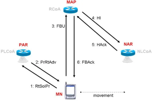
which is moving to, and the time necessary to update its HA/CN(s) using BUs. During this amount of time, MN cannot resume or continue communications. Fast Handovers allow the anticipation of the L3 handover, forming a new address in advance, redirecting data traffic to the MN's new location before it moves there, reducing signalling delay and reducing packets loss. The draft proposes two study case: the first is the “Predictive Fast Handover”, in which the MN forms the NCoA before to perform handover; the other one is the “Reactive Fast Handover”, in which the MN reacts to handover occurred. The former is the most interesting case, because it leads to better performances, but the latter is also possible and hence to be considered. See the explicative Figure 7 in both cases. In the following is described the behaviour of involved entities in case of Predictive Fast HO: for the other case see the IETF draft [12]. A MN can discover new AP(s) and send a RtSolPr (Router Solicitation for Proxy) message to its actual AR, that is the PAR, asking to it related info (e.g.: NAR’s IP address). There is also the possibility that MN requests to its PAR info about all its neighbour couple of AR(s)/AP(s), by means of sending a wildcard in the RtSolPr message. PAR responds to MN sending to it a PrRtAdv (Proxy Router Advertisement) in which puts all info in its possession for answering to MN’s requests. Based on info received, MN chooses the best couple AR/AP for its purpose, it forms a new address (the candidate NCoA) appending its current interface identifier to the NAR's prefix placed in the PrRtAdv message, then it send a FBU (Fast Binding Update) to PAR, informing it of its choice and to obtain the validation of the just formed address. In fact, the candidate NCoA could be not valid for the new subnet in which is moving to, or it could be already in use. Then PAR sends an HI (Handover Initiated) message to NAR, requesting to it to validate the NCoA formed by MN and to start buffering incoming packets destined to MN, if possible. NAR answers sending to it a HAck (Handover ACK) message, in which specifies if it can
buffer and if the MN can use the formed address: if address was not valid or already in use, then NAR inserts a new valid alternative address that the MN must use. Based on the response generated in the Handover Acknowledge (HAck) message, the PAR will either generate a tunnel to the MN’s NCoA (if the address was valid) or generate a tunnel to the NAR's address (if the address was already in use on the new subnet). In the latter case, it is assumed that there will be no time to perform another attempt to configure the MN with a CoA on the new link, so the NAR will generate a host route for the MN using its PCoA. As soon as PAR receives this message, it sends a FBAck (Fast Binding ACK) to MN, instructing it about the address formed. Now, MN can move from PAR to NAR and as soon as it detects the attachment to the new link, it sends a FNA (Fast Neighbour Advertisement) to inform the NAR about its presence and to command it to deliver data eventually buffered.
Note that MN obtained the NCoA while it was still connected to PAR, anticipated the handover process and so reducing L3 delay time necessary to form the NCoA.
But both MN and PAR may initiate the Fast HO procedure by using wireless link-layer information or link-layer triggers which inform that the MN will soon be handed off between two wireless APs, respectively attached to PAR and NAR. If the "trigger" is received at the MN, the MN will initiate the L3 handover process by sending the RtSolPr message to PAR. Instead, if the "trigger" is received at PAR, then it will transmit the PrRtAdv to the MN, without the need for solicitations.
Figure 7: FMIPv6 exchange of messages between involved entities
1.3.5. A solution for seamless mobility, integrating various
local MM mechanisms
There are currently several attempts to integrate different local mobility concepts, but the most interesting solution is shown in the following.
This solution was proposed by IETF mipshop group [13]. In this proposal, the MAP functionality may be directly integrated into the ARs (“anchoring” solution), or at a higher hierarchical level.
Integrating the MAP functionality into ARs (i.e. PARs), there is not a real advantage, because a change of address for a MN will cause a BU procedure in order to inform HA/CN(s) about the change.
If the ARs are not directly connected, but communicate through an aggregation router, then the latter would be an ideal position for the MAP functionality, avoiding to send packets forward and back on the link MAP-PAR. This solution improves the efficiency of Fast Handovers, which could
make use of the MAP to redirect traffic, thus saving delay and bandwidth between aggregation router and PAR.
Figure 8: Fast Mobile IPv6 Handover Protocol using HMIPv6
1.3.6. Network Mobility (NEMO) Technical overview
A mobile network is defined as an entire network moving as a unit, which dynamically changes its point of attachment to the Internet and thus its reachability in the topology. The mobile network is connected to the Internet via one or more Mobile Routers. The NEMO [14] basic support protocol requires the Mobile Router (MR) to maintain a bidirectional tunnel with its HA in order to preserve session continuity while the MR moves. Although the MR behaves very much like a MIPv6 mobile node, the MR updates the
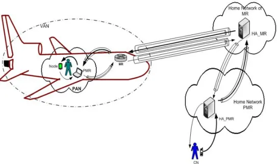
HA (by means of BUs) the entire network as opposed to only itself. The nodes within the network are able to connect to the Internet without having to participate in mobility management. Even though the NEMO protocol is fairly straight forward and it is a rational extension to the MIPv6 protocol, there are many challenges that need to be considered before the practical realization takes place. One of the major drawbacks of this protocol is non optimal routing for the mobile network nodes. Consider a typical mobile network such as a train, aircraft, ship etc. In these networks most nodes are Visiting Mobile Nodes – VMN - (passenger’s mobile devices such as mobile phones, laptops etc). If in this case a passenger uses MR support, then all packets would need to traverse via double HAs. VMNs capable of performing MIPv6 route optimization can only bypass their HA, but not the MRs Home Agent. Therefore, NEMO solution is targeted for a mobile network in which nodes are considered “dumb” (mobility unaware): obviously, it is not the typical case, since most nodes within a mobile network would be mobility aware. In a nested mobility setting the adverse effects of sub optimal routing would be more pronounced, since the route would depart more and more from the optimal as the number of nested levels increase. Figure 9 illustrates the path that a packet would traverse with the NEMO Basic support protocol, and also the bidirectional tunnelling between the MRs and their HAs. The bidirectional tunnel between the PMR and its HA gives rise to a tunnel within a tunnel.
Figure 9: visualization of Bi-directional tunnelling proposed in NEMO
1.3.6.1. Impact on Context Transfer and Advanced Handovers
When a displacement of the network occurs, only the MR changes its point of attachment to the Internet, whereas the mobile network’s (MNN) physical point of attachment in the Internet topology remains intact [15]. Hence, the MNNs perform HO entirely managed by the MR responsible for that mobile network. The main benefits of providing network mobility support transparency to the MNNs are:
The radio transmission distance from MNNs (such as on ships and aircrafts) to an on-board MR is much shorter than to another AR on the Internet. Thus by employing the MR as an AR, the MNNs can connect to the Internet via the MR using minimal power.
The MNNs don’t need to be technologically sophisticated in order to be connected via different access technologies: only the MR needs to be equipped with specialized high power communication capabilities. In some cases benefits of providing network mobility transparency are outweighed by the potential problem of sub optimal routing. Furthermore, even if there are nodes within the network that are MIPv6 capable but cannot perform a L2 HO (such as via satellite access technology), these nodes cannot make use of the capability that they have in order to achieve optimal routing. This is because the MR does not give information about the current location of the mobile network to the nodes within the network. Without having location specific information even the more capable nodes within the network cannot perform the MIPv6 route optimization procedure.
Another aspect of the NEMO architecture that we need to consider in the context of handovers is the mechanism of bidirectional tunneling between the MR and its HA. All communications to and from the mobile network is through the bidirectional tunnel and the tunnel end point at the home network end remains fairly stable. The tunnel end point at the MR’s end (which is the CoA that the MR obtains from the foreign network) keeps changing as the mobile network changes its point of attachment in the Internet topology. The MR acquires the foreign network prefix from RAs it receives from an AR. It will then auto-configure a CoA and would send this new address to its HA by means of a BU. Upon receiving this BU message the HA would send a Binding ACK message thus completing the “handover” procedure.
1.3.7. Handover decision logic in IETF solutions
In MIPv4 and MIPv6 the network layer handovers are terminal-initiated, because decision of performing a handover or less is taken solely by the MN. In fact, the network (i.e. the FA in MIPv4 or the HA in MIPv4/6) does not take an active part in this decision. Besides, network layer handover is avoided until it is strictly necessary, due to the temporary packet flow disruption and signalling overhead involved in handovers.
FMIPv6 opens up for network initiated handovers, given that an unsolicited PrRtAdv could be sent by the PAR to MN, so that the latter could use this message to configure a NCoA and send a FBU to the PAR, before to switching to the new link.
On some wireless networks, the network layer of the MN can be aware of a L2 HO by an indication from lower layers. Since an L2 HO indication in some cases or in some networks might not imply an L3 HO, the MN might have to send a Router Solicitation to confirm that a network layer HO has taken place. After having detected a network layer handover, the MN auto-configures a NCoA, it registers it with the HA and it performs RO towards all the CNs with which the MN is currently communicating.
The main HO characteristics in IETF solutions are: HO can be initiated by both ARs and MNs; could be preventive or reactive and in case of preventive HO there is the possibility to discover new ARs in the old link, or that one to acquire and validate the NCoA in the old link.
The main mechanisms involved in IETF solutions are: mechanisms for fast packet forwarding from PAR to NAR; for transferring context from PAR to NAR; bicasting packets to both PAR and NAR; hiding local mobility to HA/CN(s) thanks to MAP.
A possible classification of main F-H-MIP handovers could be as follows: Intra-AR HO (e.g. inter-RAT): this may not be seen at IP level.
Inter-AR HO with no change of MAP: this is the most important and stringent handover, that needs to be fast and efficient.
1.3.8. Consequence of a handover in IETF solutions
In MIPv4/Mipv6, MN(s) may experience degradation of network access performance due to the HO, since resources in the access network are limited. Depending on the selected protocols, other consequences of handover can include network messaging due to BUs towards HA/CN, or BUs towards MAP/ARs in order to setup tunnels for data forwarding
It should be noted that in Ambient Networks the links we deal with could be wireless, therefore it is important to minimise network messages on all links including e.g. links between ARs and MAP