43
3 Wireless
power
transfer
analysis in near-field UHF
RFID systems
Near-field coupling between antennas has been studied since a long time and most research has been focused on coupling effects in antenna arrays, field sensing for near-field antenna scanning systems, magnetic coupling between loops operating at the LF/HF frequency bands. More recently the NF coupling analysis has been applied to specific short-range radio systems, as for example NFCs (Near Field Communications) [51], microwave wireless power transfer [52]-[53] as well as RFID systems [2]. Indeed, in some UHF-RFID applications communication occurs in the antennas near-field zone, like in the HF systems, but through an electromagnetic coupling (tracking of objects moving along conveyor belts [31], RFID printers/encoders [55], desktop readers [56]).
Conventional far-field antenna parameters, as the antenna gain and the polarization/impedance mismatching coefficients, and the Friis equation are not suitable to characterize the NF-UHF radio link. The analytical evaluation of the electromagnetic coupling in the NF region is a quite difficult task, and some results are limited to configurations involving simple antenna models. In [57], the reciprocity theorem has been used to evaluate NF coupling between some antenna models for which a known source distribution can be assumed (loop, dipole or patch antennas). A NF coupling coefficient has been calculated through a series expansion starting from the vector far-field expression (measured or calculated 3D far far-field pattern) [58]. On the other hand, maximizing the wireless power transfer between reader and tag represents a key issue in improving performance of actual RFID systems and also in defining novel challenging RFID applications. Therefore, to account for the influence of different antenna shapes, antenna input impedances, and antenna relative orientation/position, full-wave numerical simulations are more suitable to give general results; numerical simulations
44
are also more convenient than expensive and time-consuming measurement campaigns, which can be obtained only for a limited set of tag-reader antennas configurations.
In this chapter, the radio link analysis for NF-UHF RFID systems has been addressed, by referring to a significant set of real commercial tag antennas [59]. Also, the numerical analysis of the antenna coupling has been performed by considering typical commercial antennas at the reader side, like patches, loops and slot antennas. Moreover, the case of a reader antenna identical to the tag antenna has been considered, namely a “matched-antenna” case that resembles the well-known matched-filter concept widely used in communication receivers and radars. Additionally, the Power Transfer Efficiency (PTE) has been evaluated for realistic tag-antenna loadings, namely an impedance equal to the complex conjugate of the tag antenna input impedance (the latter evaluated when the tag is in the far-field region of the reader antenna, that is in free-space). The ideal loading condition for maximum power transfer efficiency (PTEmax) has also been considered to get an upper bound (theoretical PTE bound [60]
calculated for any distance between the two reader and tag antennas) for the power reduction due to impedance loading mismatching.
3.1
Near-field UHF RFID modeling
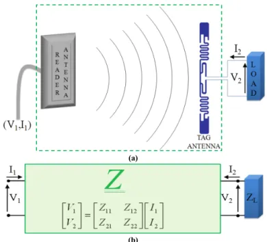
In a typical NF-UHF RFID system configuration shown in Fig. 3.1a, the tag antenna is directly connected to a load that is the chip, without any transmission line, and an impedance load equal to the conventional value of 50 Ω is rarely encountered in practical realizations (actual tags are commonly characterized by an ohmic-capacitive equivalent impedance).
The impedance matrix model adopted for the analysis of the NF-UHF RFID radio link is represented in Fig. 3.1. It results from considering the two nearby tag and reader antennas, and the space among them, as a linear two-port network, (basic theory on antenna near-field region can be found in any book on antenna theory [50]). The numerical evaluation of the entries of the impedance matrix Z has been performed through the commercial numerical tool Ansoft DesignerTM.
As a figure-of-merit of the wireless power transfer between the reader and the tag we used both the mutual-impedance (the element Z21 of the impedance matrix) and the power transfer efficiency, PTE. Z21=Z12 is equal to the open-circuit voltage at the antenna tag side divided by the input current at the reader antenna, and it is independent on the tag antenna loading.
The PTE is defined as the ratio between the power dissipated in the load of the tag antenna, PT, and the input power accepted by the reader antenna, PR:
2 1 2 2 2 2 21 2 21 2 1 2 1 22 L L in T R in L Z I Z Z P PTE Z Z P Z I Z Z (3.1)45
where Zin is the input impedance of the two-ports network when the latter is connected to ZL. As apparent from eq. (3.1), the PTE expression is given by the square of the mutual impedance amplitude (proportional to the open-circuit voltage at the tag antenna) times a coefficient also including the tag loading.
(a)
(b)
Fig. 3.1 - (a) NF-UHF RFID system scheme with reader antenna and tag antenna connected to a load and (b)
equivalent linear two-port circuit described by the Z matrix and loaded on ZL.
The diagonal terms of the impedance matrix, Z11 and Z22, coincide with the input impedance of the reader and tag antenna, respectively, when the latter are in free-space (in practice when they are separated by a distance larger than some tens of centimeters, as it will be shown later). In the following, above input impedances for the stand-alone antennas will be denoted by ZR and ZT, respectively (consider that such values are not constants as they are frequency-dependent). Also, it is well known that for reader-tag coupling in the far-field region the impedance matching condition ZL=ZT* (the symbol ‘*’ denotes the complex conjugate operator) is that one that maximizes the PTE when the two antennas are in each other’s far-field region:
2 max 4 FF T R PTE G G d (3.2)
where GT and GR are the tag and reader antenna gains, respectively, d is the antennas distance, is the polarization matching coefficient and is the impedance matching
46
2 4 L T L T Z Z Z Z (3.3)It is worth noting that differently from the power transfer efficiency parameter used in [54] and [57], the impedance matching coefficient at the reader side is not included in the PTE definition (namely, PR is the input power at the reader antenna and not the available power at the reader side).
While the mutual-impedance, Z21, only depends on the relative orientation/position of the two antennas, the PTE also depends on the tag antenna loading. Two different loading conditions have been considered:
conjugate-matched case: the load impedance is equal to the complex conjugate of the free-space tag antenna impedance, the latter evaluated at a given fixed frequency f0: ZL=ZT*(f=f0); this condition maximizes the power transfer efficiency,
at f=f0, under the far-field condition: max *
0
FF
L T
PTEPTE Z Z f f ;
the load impedance is set equal to the optimal load impedance, ZL=Zopt, to achieve maximum power transfer (named as Linville load in section 8.6 in [50]):
max
NF
L opt
PTEPTE PTE Z Z , where the analytical closed form expressions for both Zopt and max
NF
PTE can be found in [60], as a function of the impedance matrix entries; those expressions are valid for any distance between the two antennas as they are relevant to a general two-port network.
When the two antennas are far enough, this case coincides with the conjugate-matched condition ZL=ZT*, since in the far-field Zopt approaches Z22* and Z22 approaches ZT (and then maxNF maxFF
PTE PTE , as will be numerically verified in next paragraphs).
3.2
Reader and tag antennas
Ansoft DesignerTM, a method-of-moments based commercial numerical tool, has been used to characterize stand-alone tag/reader antennas, and then to construct the impedance matrix for a number of antenna pairs.
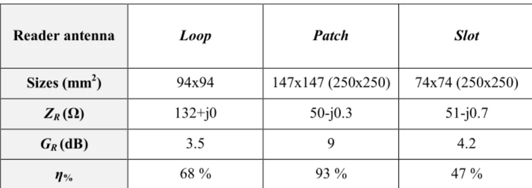
The reader antennas we considered and their free-space input impedance, gain and efficiency (assuming that they are made of 0.0035 mm thick copper) are summarized in Tab. 3.1. The input impedance, ZR, the gain and efficiency of the isolated reader antennas are evaluated at the central frequency of the 860-960 MHz frequency band, (i.e. 910 MHz). Reader antennas are a square patch antenna with a coaxial feed, a square loop antenna and a square ring slot antenna, so including most of the technologies used in commercial planar reader antennas. All reader antennas are linearly polarized. In the following we refer briefly to them as patch, loop and slot respectively.
47
Reader antenna Loop Patch Slot
Sizes (mm2) 94x94 147x147 (250x250) 74x74 (250x250)
ZR (Ω) 132+j0 50-j0.3 51-j0.7
GR (dB) 3.5 9 4.2
η% 68 % 93 % 47 %
Tab. 3.1 - Reader antenna sizes, input impedance, realized gain and efficiency at the UHF central frequency
f0=910 MHz.
The antennas considered on the tag side are from a set of commercial passive tag antennas [59], properly ordered on the basis of their dimensions and reading range as listed in Tab. 3.2. Tags are designed typically for far-field applications, but the UH100 has also good NF performance. Indeed the UH113 tag (the smaller one) is specific for NF applications. A numerical model of each tag antenna has been extracted from some real tag samples [59]. We noted a small discrepancy between the numerical values of ZT and the complex conjugate of the input impedance of the corresponding tag chip (the latter extracted from tag datasheet [61], if available). This can be due to the several factors: both above impedances vary significantly in the UHF-RFID frequency bands; the chip input impedance actually represent an equivalent input impedance of a non-linear electronic front-end; finally, the numerical model we extracted from the real tag antennas necessarily include tolerance errors (although we did our best to get them below 1 mm).
Tag antenna UH100
UH423 UH113
Sizes (mm2) 94x7.8 50x30 32x18
ZR (Ω) 26.3+j222.9 24.4+j232.9 20.6+j235.1
GR (dB) 1.7 0.8 0.7
η% 72 % 76 % 61 %
Tab. 3.2 - Tag antenna sizes, input impedance, realized gain and efficiency at the UHF central frequency
f0=910 MHz.
As far as the radiation efficiency is concerned, it is worth noting that high antenna radiation efficiency is needed to maximize PTE. Each tag antenna represents also a
48
reader antenna because in our numerical analysis we consider the “matched-antenna” system with reader and tag having the same antenna.
An example of the simulated reader/tag system with loop antenna (reader antenna) and a UH423 tag (Loop/UH423) is depicted in Fig. 3.2, when the antenna lye on parallel planes and they are aligned to meet the polarization matching condition (by referring to an hypothetical far-field case).
Fig. 3.2 - UHF RFID system configuration with a loop antenna (reader antenna) and the tag UH423
(Loop/UH423).
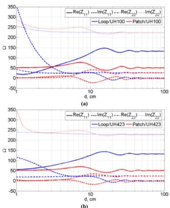
The first numerical tests were focused on finding the minimum distance d between the reader and the tag antennas at which a) the amplitude self-impedances of the impedance matrix, Z11 and Z22, can be considered independent on the distance and b) the mutual-impedance exhibits a 1/d algebraic decay (typical of the antenna coupling in far-field region) 20 dB/decade amplitude decay. Index 1 indicates the reader port and index 2 indicates the tag one. Fig. 3.3 shows the self-impedance parameters obtained at 910 MHz, by referring to the antenna pairs Loop/UH100, Patch/UH100 (Fig. 3.3a) and Loop/UH423, Patch/UH423 (Fig. 3.3b). After some oscillations at around 30 cm, the self impedances approach to a fixed value.
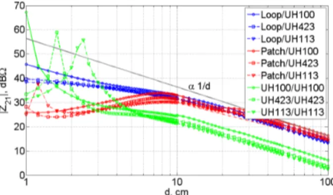
In Fig. 3.4 the mutual impedance Z21 is shown for the following couples: Loop/UH100, Loop/UH423, Loop/UH113, Patch/UH100, Patch/UH423 and Patch/UH113. Curves reach a 1/d algebraic decay near to 30 cm. So considering the impedance parameters behavior, we can fixed the far-field distance at the value dFF=30 cm (corresponding to 0.9λ, at 910 MHz). The above value has been verified for all possible combinations of the antennas in Tab. 3.1 and Tab. 3.2, for a set of frequencies in the 860-960 MHz range, and for a set of different orientations of the tag antennas in the plane parallel to that one containing the reader antenna.
49 (a)
(b)
Fig. 3.3 - Self impedances Z11 and Z22 versus distance for the NF-UHF RFID system configurations (a)
Loop/UH100, Patch/UH100 and (b) Loop/UH423 and Patch/UH423 (f0=910 MHz).
Fig. 3.4 - Mutual impedance Z21 versus distance for the NF-UHF RFID system configurations Loop/UH100,
Loop/UH423, Loop/UH113, Patch/UH100, Patch/UH423 and Patch/UH113 (f0=910 MHz).
3.3
Matched-antenna configuration
Starting from well-established products and know-how on UHF-RFID components for long reading ranges, NF-UHF RFID systems can be realized in different ways. According to the general classification proposed in [4] and [57], the different
50
approaches can be subdivided as follows: using standard readers and tags, using low-power reader, using short-range tag, developing ad hoc reader and tag antennas for NF coupling.
For applications involving item level tagging, tag printers/encoders and tagging of items/cases moving along a conveyor belt, a further approach could be considered where the reader antenna is chosen to match the specific conventional UHF tag (or tag class) that is going to be used in one of the above applications. Specifically, the idea is to use for the reader the same antenna topology as for the tag. It can be named as a “matched-antenna” configuration, when having in mind the well-known matched-filter technique used to maximize the signal-to-noise ratio when filtering the received signal of a communication system or radar. The NF coupling between identical antennas has been already considered several times in the open literature, as for example when studying coupling effects in antenna arrays or the magnetic coupling between loop antennas. The power transfer efficiency in RFID systems using identical antennas for the tag and the reader sides have also been studied [51], but just referring to two conventional dipoles or loops, instead of two actual commercial UHF RFID tag antennas.
To illustrate the Z21 features of the NF coupling between two identical tags, some numerical results are shown in this paragraph. The mutual coupling between the NF-UHF RFID system configurations shown in Fig. 3.4 are compared with the corresponding “matched-antenna” systems UH100/UH100, UH423/UH423 and UH113/UH113 in Fig. 3.5. At the central frequency of 910 MHz, the “matched-antenna” configurations show an higher mutual coupling and a maximum coupling distance exists: dpeak=1 cm for UH100/UH100, dpeak=1.6 cm for UH423/UH423,
dpeak=2.4 cm for UH113/UH113.
Fig. 3.5 - Mutual impedance Z21 versus distance for the following NF-UHF RFID system configurations:
Loop/UH100, Loop/UH423, Loop/UH113, Patch/UH100, Patch/UH423, Patch/UH113, UH100/UH100, UH423/UH423 and UH113/UH113 (f0=910 MHz).
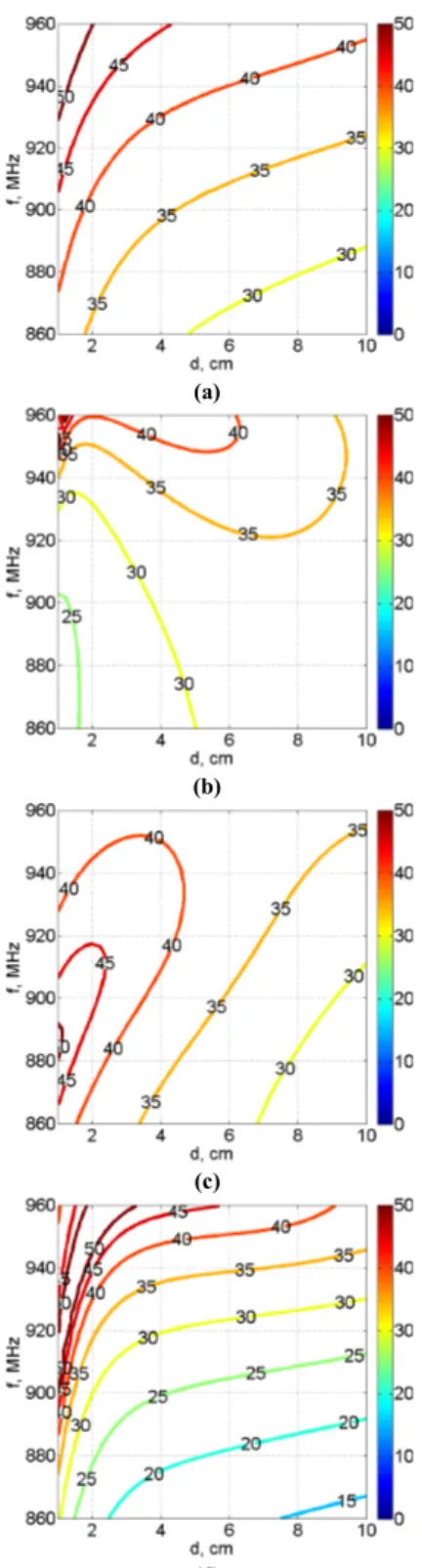
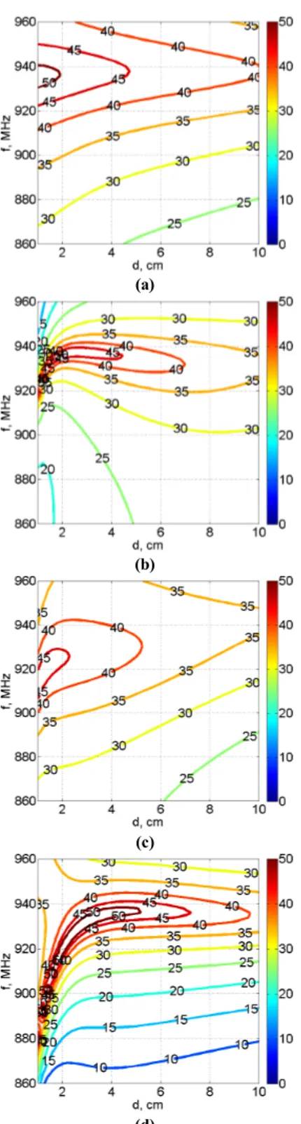
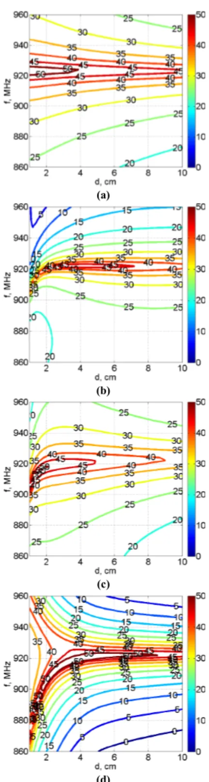
In Fig. 3.6-Fig. 3.8 a contour plot of the mutual impedance has been represented as a function of both distance and frequency for all possible combinations of the antennas in Tab. 3.1 and Tab. 3.2.
51 (a)
(b)
(c)
(d)
Fig. 3.6 - Contour plot of the mutual impedance Z21 versus distance and frequency for the NF-UHF RFID
52 (a)
(b)
(c)
(d)
Fig. 3.7 - Contour plot of the mutual impedance Z21 versus distance and frequency for the NF-UHF RFID
53 (a)
(b)
(c)
(d)
Fig. 3.8 - Contour plot of the mutual impedance Z21 versus distance and frequency for the NF-UHF RFID
54
The considered distance is just between 1 cm and 10 cm, because the most important variations occur in this region. The Z21 peak appears in the “matched-antenna” configuration as evident from the more rapidly variations of curves in Fig. 3.6d-Fig. 3.8d. The Z21 peak position changes respect to the frequency but it is always within the 10 cm distance. In all the other configurations the curves variations are smoother.
3.4
Power transfer efficiency results
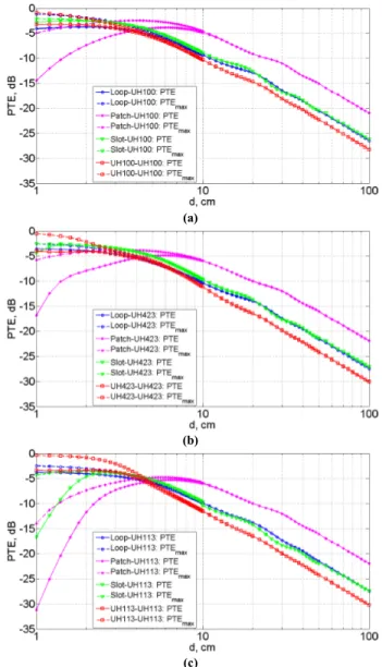
The numerical results relevant to the PTE for different antenna pairs will be shown in Fig. 3.9. The PTENF calculated in the real case of ZL=ZT* is compared with the
max NF
PTE obtained in the ideal optimum case (ZL=Zopt) at the central frequency of 910 MHz with respect to the distance between the considered antennas. We briefly refer to them as PTE and PTEmax. The theoretical upper bound of PTEmax=0 dB can be typically
obtained for electrically small antennas (l≤0.1λ). In our case, just the UH113 tag is near 0.1λ, indeed its PTEmax reached the higher value of -0.3dB in the “matched-antenna”
configuration. Instead UH100 and UH423 tags are 0.3λ and 0.15λ respectively, so their
PTEmax is lower.
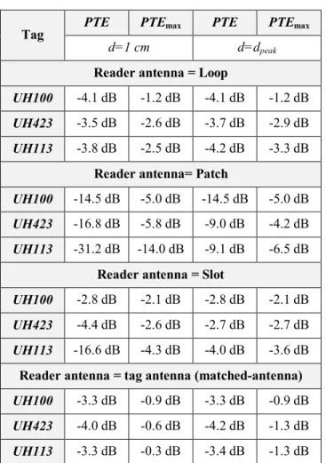
To simpler understand the results in Fig. 3.9 in Tab. 3.3 the different configurations performance are summarized in terms of PTE and PTEmax for two different distances
between the reader and tag antennas: d=1 cm and d=dpeak (corresponding |Z21| peak distance).
The PTEmax in the NF region reaches higher value with the “matched-antenna”
configuration and it is closer to the theoretical bound of PTEmax=0 dB. The advantage is
more clear if the tag is smaller, indeed in the UH113/UH113 system for d=dpeak, the
PTEmax is 2 dB, 5.2 dB and 2.3 dB higher respect to the Loop/UH113, Patch/UH113 and
Slot/UH113 configurations respectively. The above considerations on PTEmax have been
confirmed by the PTE behavior even if in this case the “matched-antenna” configuration the gain in terms of PTE is lower due to the effects of the real load (ZL=ZT*). With the patch as reader, performance are better in the far- field region, as we expected, because it is an antenna designed to work in that zone.
Simulations have been done within the frequency bandwidth (860-960 MHz) for the above system configurations (Fig. 3.10-Fig. 3.12) for a limited set of distances between 1 cm and 10 cm. The dashed lines limit the region in which the indicated PTEmax value
can be obtained. Comparing these with the solid line of the PTE, we can see how much we loss in the real case.
Using the patch as a reader antenna, a PTEmax>-3 dB has been reached just with the
UH100 tag, moreover, the real performance curve shows that the PTE never reaches the -3 dB value, so it is not suitable to be used in such NF applications.
With the loop or slot reader antenna, the PTEmax≥-3 dB area exists, but its extension
55 at all.
With the proposed “matched-antenna” configuration, the area PTEmax≥-3 dB exists with
all the considered tags. The real performance of the PTE confirms this results, so it looks like the most reliable configuration for NF-UHF RFID systems with different tag topology.
(a)
(b)
(c)
Fig. 3.9 - PTE and PTEmax versus distance for the following NF-UHF RFID system configurations: (a)
Loop/UH100, Patch/UH100, Slot/UH100 and UH100/UH100, (b) Loop/UH423, Patch/UH423, Slot/UH423 and UH423/UH423 (c) Loop/UH113, Patch/UH113, Slot/UH113 and UH113/UH113 (f0=910 MHz).
56
Tag PTE PTEmax PTE PTEmax
d=1 cm d=dpeak
Reader antenna = Loop
UH100 -4.1 dB -1.2 dB -4.1 dB -1.2 dB
UH423 -3.5 dB -2.6 dB -3.7 dB -2.9 dB
UH113 -3.8 dB -2.5 dB -4.2 dB -3.3 dB
Reader antenna= Patch
UH100 -14.5 dB -5.0 dB -14.5 dB -5.0 dB
UH423 -16.8 dB -5.8 dB -9.0 dB -4.2 dB
UH113 -31.2 dB -14.0 dB -9.1 dB -6.5 dB
Reader antenna = Slot
UH100 -2.8 dB -2.1 dB -2.8 dB -2.1 dB
UH423 -4.4 dB -2.6 dB -2.7 dB -2.7 dB
UH113 -16.6 dB -4.3 dB -4.0 dB -3.6 dB
Reader antenna = tag antenna (matched-antenna)
UH100 -3.3 dB -0.9 dB -3.3 dB -0.9 dB
UH423 -4.0 dB -0.6 dB -4.2 dB -1.3 dB
UH113 -3.3 dB -0.3 dB -3.4 dB -1.3 dB
Tab. 3.3 - PTE and PTEmax for different NF-UHF RFID system configurations at 910 MHz for two distances:
d=1 cm and d=dpeak.
A limited but significant set of relative orientations between the two tag and reader antennas have been considered. By supposing as fixed the reader antenna, the tag antenna can be aligned to satisfy the polarization matching condition (by presuming a far-field case), or can be 90° or 180° rotated with respect to the first case. While the 180° rotation does not apparently change the far-field PTE value, this is not the case when the two antennas are very close, even when the tag antenna exhibits remarkable symmetry properties (see tags in Tab. 3.2). This is due to the fact that in the NF region all the field components contribute to the coupling and the reactive components can give a dominant contribution with respect to the radiating ones.
Fig. 3.13 shows the PTE and the PTEmax for all the configurations in Fig. 3.9 in the
case of polarization mismatching (reciprocal orientation of 90°) between reader and tag antennas at the central frequency (f0=910 MHz). In the NF region, the “matched-antenna” configuration shows a higher PTE, so it looks like the more robust solution with respect to the polarization mismatching between the antennas.
57 (a)
(b)
(c)
(d)
Fig. 3.10 - Contour plot of the PTE and of the PTEmax versus distance and frequency for the following
NF-UHF RFID system configurations: (a) Loop/UH100, (b) Patch/UH100, (c) Slot/UH100 and (d) UH100/UH100.
58 (a)
(b)
(c)
(d)
Fig. 3.11 - Contour plot of the PTE and of the PTEmax versus distance and frequency for the following
NF-UHF RFID system configurations: (a) Loop/UH423, (b) Patch/UH423, (c) Slot/UH423 and (d) UH423/UH423.
59 (a)
(b)
(c)
(d)
Fig. 3.12 - Contour plot of the PTE and of the PTEmax versus distance and frequency for the following
NF-UHF RFID system configurations: (a) Loop/UH113, (b) Patch/UH113, (c) Slot/UH113 and (d) UH113/UH113.
60 (a)
(b)
(c)
Fig. 3.13 - PTE and PTEmax versus distance in the mismatching case (reciprocal orientation of 90°) for the
following NF-UHF RFID system configurations: (a) Loop/UH100, Patch/UH100, Slot/UH100 and UH100/UH100, (b) Loop/UH423, Patch/UH423, Slot/UH423 and UH423/UH423 (c) Loop/UH113, Patch/UH113, Slot/UH113 and UH113/UH113 (f0=910 MHz).
3.5
Conclusions
A detailed numerical analysis of the wireless power transfer between NF coupled UHF-RFID reader/tag antennas has been performed. The approach based on an equivalent impedance matrix allowed us to separately analyze the effect on the power transfer efficiency of the antenna mutual impedance and the tag loading condition. It has
61
though near-field antenna coupling is a well established field, it is presumed that the results here presented are useful to whom is working in the RFID field since results are specific for NF-UHF RFID applications and consider real widespread commercial tag antennas. The field power transfer efficiency (eq. (3.2)) only depends on the far-field parameters of the two antennas (radiation patterns, antenna gain, input impedance of the stand-alone antenna) which can be extracted from the vector radiating field; on the other hand, the NF coupling is determined by the NF behavior of all the field components (not only the radiating ones) and it is specific for each antenna, so that considering real UHF tag antennas instead of simplified models can be important.
In most of the cases here analyzed, a high efficiency coupling can be reached when the reader antenna is equal to the tag antenna (“matched-antenna” configuration), as we can see from the extended -3 dB PTE region in the contour plot, even in the case of polarization mismatching. The proposed solution looks like more independent from the tag sizes. The above results will be further investigated to validate our idea by considering environmental phenomena, like multipath or the presence of material objects close to the tag antennas.