Alma Mater Studiorum — Universitá di Bologna
Campus di Cesena
Scuola di Ingegneria e Architettura
Corso di Laurea in Ingegneria Informatica
Titolo dell’elaborato
Model Checking of Software Defined Networks using
Header Space Analysis
Elaborato in
Network Security
Relatore
Franco Callegati
Walter Cerroni
Presentata da
Alessandro Molari
Sessione II
Anno Accademico 2016/2017
This work is for my parents Claudio and Oriena, who made my studies possible,
my wise brother Luca, my best friend, super-hero and source of inspiration,
my dear sister Denise, who supported me in the darkest moments,
my lovely cat Paolo, who kept me warm, with whom I shared many unique moments,
the Cyber Security and Hacking group CeSeNA,
and for all those who believed in me.
Contents
Abstract 6
Chapter 1. Software Defined Networks 7
1. Introduction 7
2. Planes 7
3. Principles 7
4. Abstractions 8
5. Interfaces 9
Chapter 2. SDN Control Plane implementation 11
1. Southbound Interface: OpenFlow 11
1.1. Introduction 11
1.2. OpenFlow switch 11
1.3. OpenFlow protocol 14
2. SDN Controller: ONOS 15
2.1. Architecture 15
2.2. Tiers, Sub-systems, Components 16
Chapter 3. Security in SDN 19
1. Introduction 19
2. Security vulnerabilities, attacks and challenges 20
3. Some practical cases / examples 21
4. Summing up 21
Chapter 4. Header Space Analysis 23
1. Introduction 23 2. Taxonomy 23 2.1. header (h) 23 2.2. header space (H) 23 2.3. wildcard expression (w) 24 2.4. flow (f) 24 2.5. network box (n) 24 2.6. network space (N) 24
2.7. network transfer function (Ψ) 24
2.8. topology transfer function (Γ) 24
2.9. slice transfer function (Ψs) 24
2.10. permission (P ) 24
2.11. slice network space (Υ) 24
2.12. slice (S) 24
3. Modelling network boxes with HSA 25
3.1. IPv4 Router 25
4 CONTENTS 3.2. Firewall 25 3.3. NAT 25 4. HSA algebra 25 4.1. Intersection 26 4.2. Union 26 4.3. Complementation 26 4.4. Difference 26 5. Reachability use-case 26 6. HSA issues 27 Chapter 5. NetPlumber 29 1. Plumbing Graph 29 2. Sync with SDN 30 3. Policy check 30
4. Reachability check use-case 31
Chapter 6. Model Checking Service 33
1. Vision 33
2. Goals 33
2.1. The development process 33
2.2. Think about problems, not solutions 33
2.3. First things first 33
2.4. Encourage software reuse 34
3. Requirements 34 4. Case Study 34 5. requirements analysis 36 5.1. Glossary 36 5.2. Requirements Model 37 5.3. functional requirements 37 5.4. non-functional requirements 39 6. use-cases 41 7. domain model 42
8. problem analysis (logic architecture) 43
8.1. UI Structure 43
8.2. Services Structure 44
8.3. Operation Handling Structure 45
8.4. Operation Data Types 46
8.5. network model Data Types 47
8.6. SDN Data Types 48
8.7. Execute-Operation Interaction 49
8.8. Show-Policy-State Interaction 50
8.9. network model Interaction 51
8.10. Check-Reachability Interaction 52
9. Abstraction Gap 52
10. Risk Analysis 53
11. project 53
11.1. Services Structure 53
11.2. Operation Handling Structure 55
11.3. Operation Data Types 56
CONTENTS 5 11.5. SDN Data Types 58 11.6. UI Interaction 59 11.7. Check-Reachability Interaction 59 12. Implementation 60 13. Tests 60 14. Demo 60 14.1. Results 61 14.2. Summing up 78 Bibliography 79
6 CONTENTS
Abstract
This thesis investigates the topic of verifying network status validity with a Cyber Security perspective.
The fields of interest are dynamic networks like OpenFlow and Software Defined Net-works, where these problems may have larger attack surface and greater impact.
The framework under study is called Header Space Analysis, a formal model and protocol-agnostic frameworkthat allows to perform static policy checking both in classical TCP/IP networks and modern dynamic SDN.
The goal is to analyse some classes of network failure, declaring valid network states and recognizing invalid ones.
HSA has evolved in NetPlumber, to face problems caused by high dynamics of SDN networks. The main difference between HSA and NetPlumber is the incremental way that the latter performs checks and keeps state updated, verifying the actual state compliance with the expected state defined in its model, but the concept is the same: declare what’s allowed and recognize states violating that model.
The second and main contribute of this thesis is to expand existing vision with the purpose of increasing the network security degree, introducing model-checking-based networks through the definition of an abstraction layer that provides a security-focused model-checking serviceto SDN.
The developed system is called MCS (Model Checking Service) and is implemented for an existing SDN solution called ONOS, using NetPlumber as underlying model-checking technology, but it’s validity is general, uncoupled with any kind of SDN implementation.
Finally, the demo shows how some cases of well-known security attacks in modern networks can be prevented or mitigated using the reactive behavior of MCS.
CHAPTER 1
Software Defined Networks
1. Introduction
In the last years digitisation and interconnection of society brought a greater usage of tradi-tional TCP/IP networks.
However the Internet protocol stack was designed looking society of the late ’70s, not today. Use-cases changed and today’s demand isn’t the same as it was before.
Now, traditional IP networks are complex and very hard to manage. It is both difficult to configure the network according to predefined policies and to reconfigure it to respond to faults, load and changes.
The main criticism is current networks are vertically integrated: decisions about how traffic should be handled are coupled with its forwarding.
In this scenario, modern standards have been proposed, such as OpenFlow from Stan-ford University. OpenFlow is then evolved in a dynamic networking structure called Soft-ware Defined Network.
2. Planes
SDN[5] breaks vertical integration into two planes. Every plane has a well-defined set of responsibilities:
• Control Plane (CP):
Decides how to handle network traffic. • Data Plane (DP):
Forwards traffic according to the decisions made by the Control Plane, without making any decision.
In this scenario, OpenFlow is just a possible implementation of the Data Plane. This approach allows to centralize decisions in a logically centralized controller. Finally, Management Plane (MP) is defined as the set of applications that leverage functions offered by the NOS (in particular the Northbound Interface) to define policies, which are translated to southbound-specific instructions that program the behaviour of Forwarding Devices.
3. Principles SDN architecture has four pillars:
(1) Control Plane and Data Plane are decoupled: network devices will become simple forwarding elements.
(2) Forwarding decisions are flow-based, instead of destination-based. A flow is de-fined by a set of packet field values acting as match criterion and a set of actions that define what to do. Flow abstraction allows unifying the behavior of different types of network devices, including switches, firewalls, routers, . . .
8 1. Software Defined Networks
(3) Control logic is moved to an external entity called SDN Controller (or Net-work Operating System), that provides resources and abstractions to facilitate the programming of forwarding devices based on a logically centralized abstract network view.
Logical centralization of control logic makes simpler and less error-prone to modify network policies through high-level languages and software components.
Also, centralization of control logic in a controller with global knowledge of the net-work state simplifies the development of more sophisticated Virtual Netnet-work Func-tion.
(4) Network is programmable through software applications running on top of NOS, that interacts with the underlying Data Plane devices.
Figure 1. SDN architecture
4. Abstractions
From a application point-of-view, SDN can be defined by three abstractions:
(1) Forwarding abstraction: Should allow any forwarding behavior desired by network applications while hiding details of the underlying hardware. OpenFlow is one example of such abstraction. It allows to reason about Forwarding Devices (FDs) instead of physical devices: hardware or software-based Data Plane device that perform a set
5. INTERFACES 9
of elementary operations through a well-defined instruction set (for example flow rules) used to take actions on the incoming packets.
(2) Distribution abstraction: Network applications should be shielded from the vagaries of distributed state, making the distributed control problem a logically centralized one. Its realization requires a common distribution layer, called SDN controller (or Net-work Operating System).
(3) Specification abstraction: Network applications should be able to express the desired network behavior without being responsible for implementing that behavior itself. This can be achieved because specification layer maps the global view of the physical network (provided by the SDN controller) into simplified abstract models that can be used by network applications.
5. Interfaces
Interaction between SDN layers is regulated by the following interfaces:
• Southbound Interface (SBI): The instruction set of the Forwarding Devices is defined by the southbound API. SBI can be seen as the connecting bridge between NOS and FD, the main instrument used to clearly separate the Control Plane with the Data Plane, thus these APIs are still tightly tied to the Forwarding Devices of the underlying physical (or virtual) infrastructure.
• Northbound Interface (NBI): The Network Operating System can offer an API to application developers. This API represents the Northbound Interface.
CHAPTER 2
SDN Control Plane implementation
1. Southbound Interface: OpenFlow
1.1. Introduction. OpenFlow[2] is a possible (and commonly used) Southbound In-terface. It allows interoperability and the deployment of vendor-agnostic network devices.
1.2. OpenFlow switch. An OpenFlow switch consists of: • One or more Flow Tables
• A Group Table • A OpenFlow channel
The Flow Tables and Group Table are used to perform packet lookups and forwarding. The OpenFlow channel is used to communicate with the SDN Controller, both to inform about new events and to let SDN Controller manage the OpenFlow switch via the OpenFlow protocol.
Figure 1. OpenFlow switch
The OpenFlow pipeline contains multiple Flow Tables. Flow Tables are sequentially numbered, starting from 0. Each Flow Table contains multiple Flow Entries.
Pipeline processing defines how incoming packets are consumed by Flow Tables and what result is produced.
When there is an incoming packet in a OpenFlow switch, it is matched against the Flow Entries of the first Flow Table to select a Flow Entry.
12 2. SDN Control Plane IMPLEMENTATION
The following figure shows how a Flow Entry is structured:
Figure 2. Flow Entry
Where:
• Match Fields: Used to match against packets. These consist of the ingress port and packet headers, and optionally metadata specified by a previous table.
• Priority: Matching precedence of the Flow Entry. • Counters: Updates for matching packets.
• Instructions: instructions that should be added to the Action Set. • Timeouts: maximum amount of time before flow is expired
• Cookie: opaque data value chosen by the controller. It may be used to filter flow statistics, modification, deletion, . . . . It is not used when processing packets.
Pipeline processing typically go through next tables until the last table is reached and the instructions available in the Action Set will be executed.
If a matching Flow Entry does not direct packets to another Flow Table, pipeline processing stops at this table. When a pipeline processing stops, the packet is processed with its Action Set and usually forwarded.
If a packet does not match a Flow Entry in a Flow Table, there is a Table Miss. The behavior of a Table Miss depends on the table configuration, for example: dropping packets, passing them to another table, sending them to SDN Controller via messages.
1. Southbound Interface: OpenFlow 13
Figure 3. Packet processing Possible instructions include:
• Meter meter-id (optional): Direct packet to the specified meter.
• Apply-Actions actions (optional): Applies the specific actions immediately, without changing the Action Set.
• Write-Actions actions (required): Merges the specified actions into the current Ac-tion Set.
14 2. SDN Control Plane IMPLEMENTATION
• Clear-Actions(optional): Clears all the actions in the Action Set.
• Write-Metadata metadata (optional): Writes the masked metadata value into the metadata field.
• Goto-Table next-table-id (required): Indicates the next table in the processing pipeline (must be greater than the current table). Flow Entries of the last Flow Table cannot include this instruction.
1.3. OpenFlow protocol. The provides three information sources for Network Op-erating System:
• Controller-to-Switch Messages: Messages initiated by the controller and may or may not require a response from the switch.
Examples include:
– Features: Message to request switch capabilities.
– Modify-State, Read-State: Messages to read and modify switch state. – Configuration: Message to change switch configuration.
– Packet OUT: Message to send packets in the specified port on the switch and, thus, to forward packets received via a Packet IN message. Message must also contain a list of actions that the switch should apply for that packet.
– Barrier: Barriers are request/reply messages used to ensure message dependencies have been met or to receive notifications for completed operations.
• Asynchronous Messages: Messages sent without a controller soliciting them from a switch. Switches send asynchronous to controllers to denote an event, such as packet arrival, switch state change, error, . . .
Examples include:
– Packet IN: Transfer control of a packet to the controller. This kind of event is always sent for (1) packets forwarded to port CONTROLLER (2) table-miss Flow Entry is hit.
– Flow-Removed: Inform the controller about the removal of a Flow Entry from a Flow Table.
– Port-status: Inform the controller of a change on a port.
• Symmetric Messages: Messages sent without solicitation, in either direction. A typical SDN controller manages multiple OpenFlow channels, each one to a different OpenFlow switch.
An OpenFlow switch typically have one OpenFlow channel to a single SDN Con-troller.
Once connection between a switch and the SDN Controller has been established, they negotiate the protocol version to be used. Then, other messages following the negotiated protocol version can be exchanged through the channel.
2. SDN Controller: ONOS 15
2. SDN Controller: ONOS
2.1. Architecture. ONOS[6] is a SDN controller solution organized as a multi-module OSGi project, where modules are managed as OSGi bundles.
OSGidefines an architecture for developing and deploying modular systems. Its architecture is layered:
Figure 4. architecture Where:
• Bundles: Bundles are the OSGi components made by the developers.
• Services: The services layer connects bundles in a dynamic way by offering a publish-find-bind model for plain old Java objects.
• Life-Cycle: The API to install, start, stop, update, and uninstall bundles. • Modules: The layer that defines how a bundle can import and export code. • Security: The layer that handles the security aspects.
• Execution Environment: Defines what methods and classes are available in a specific platform.
Every bundle has its own lifecycle:
16 2. SDN Control Plane IMPLEMENTATION
In ONOS this allows to build an open system where modules can be added on-demand and are decoupled from the core that handles the main NOS functionality and provides main network abstractions.
Inside a bundle, multiple OSGi components and services can be defined.
This perfectly maps to the concept of ONOS service. In fact, both have dependencies and a lifecycle. For this reason, most of ONOS services are implemented as OSGi services.
2.2. Tiers, Sub-systems, Components. ONOS system is organized in tiers. Each tier hosts some sub-systems and a well-defined interface. Tier interfaces are used to perform inter-tier interaction. Each sub-system is a collection of components making up a service that provides the desired functionality.
Figure 6. ONOS Tiers As shown above, a sub-system can span over multiple layers. In particular:
• Northbound API Tier allows to the applications to use defined services. • Core Tier defines Manager abstraction. It allows to translate low-level services
defined in Southbound Interface to high-level services defined in Northbound Interface and to receive information from applications.
2. SDN Controller: ONOS 17
• Southbound API Tier allows to the Core Tier to interact with Providers Tier via two main abstractions: ProviderService and ProviderRegistry.
• Providers Tier defines protocol-specific implementation of the desired function-alities. For example for devices sub-system there are: OpenFlowDeviceProvider, OVSDBDeviceProvider, . . .
• Providers Tier defines protocol-specific implementation of the desired functional-ities.
• Protocols Tier allows to interact with forwarding elements, by implementing needed communication protocols.
CHAPTER 3
Security in SDN
1. Introduction
In early days of SDN, security wasn’t considered as an important factor, thus SDN resulted to be very insecure by design.
The architecture of SDN introduces radical changes in the vertical network integration model by decoupling Data Plane from the Control Plane. This poses new threats both from internal and external actors and a much more broader attack surface than in static networks.
In particular, the logical centralization of the network intelligence put the entire network at risk if the SDN Controller is compromised.
Moreover, even if SDN Controllers aren’t compromised, but just a single network box’s security fails, it can compromise the SDN Controller state and thus the entire network.
This is possible because pure SDN solutions available today don’t have the concept of se-curity isolation. On the other hand, each layer of SDN has its own sese-curity requirements and implications.
Since a single point of control can gain entire network control, a single point of failure can possibly exploit the entire network.
Imagine if you request a bank transaction and your sensitive information is stolen just because somewhere, not even between you and the bank, a network box is compromised, injecting malicious flow-rules to remove you from the network.
Imagine if your pacemaker monitoring solution stops working, and cannot communicate with your medical institute about health problems, just because networking failed due to a compromised SDN Controller that has infected the remaining parts of the network system.
These are just simple Denial-of-Service (DoS) attacks, but also more complex attacks are feasible.
The centralized knowledge base can be used for further attacks, like reprogramming the entire network to modify the network flow or to steal sensitive information.
Here, the principle “Security Is Everyone's Responsibility” can't be applied: a compromised network box can’t compromise the entire network. Compromised sources need to be recognized and they shouldn’t interfere with the rest of the network.
Security must be built as part of SDN architecture to ensure the integrity of the network system.
As always, we need to face a technology that isn’t secure by design. SDN research moved from analysing network problems to security problems.
Many ideas and solutions have been proposed but none of them became the de-facto standard. In the rest of this thesis we will try to use a formal model (called Header Space Analysis) and its evolution (called NetPlumber) to address network security issues in Software De-fined Network.
20 3. SECURITY IN SDN
2. Security vulnerabilities, attacks and challenges
SDN networks provide advanced and complex solutions that involve many actors to interact in a way that is programmable.
This amplifies the attack surface of existing threats and leads to new vulnerabilities in various SDN layers[1]:
4. SUMMING UP 21
3. Some practical cases / examples • Malicious or compromised Network Application:
– DoS chained applications
– sidesteps to use chained applications authorizations
– modifies SDN Controller database to change its perception of the underlying network
– retrieves SDN Controller information as part of the reconnaissance stage of infection
– overwrites flow rule or clear a flow table to cause unexpected network behaviour and trigger attacks at lower levels, like network boxes DoS, Man-in-the-Middle attacks, . . .
– exhausts all the available system resources and affect performance or DoS other Network Applications
– exploits SDN Controller and thus can execute system commands, like exit to terminate the controller
• If a Network Application is compromised and its information is used somewhere else, for example a DBMS containing user sensitive data, other applications may use those information without knowing that the source shouldn’t be trusted because it was compromised. That is due to compelling mechanisms to establish trust to certify SDN Controller and Network Applications don’t exist yet
• Malicious or compromised network box:
– floods a target SDN Controller with Packet IN, in order to compromise it – forges and sends a ARP packet relayed as Packet IN, fooling the SDN
Con-troller into installing malicious flow rules to divert traffic flows, possibly for eavesdropping, thereby allowing a malicious host to intercept traffic intended for another host
– along with another accomplice, initiate arbitrary flows to fool the OpenFlow switch and the SDN Controller into installing flow rules that create loops or black-holes in the network
– uses the Southbound Interface to modify Control Messages exchanged between the Control Plane and the Data Plane, such as flow-rule messages to corrupt network behaviour
– steals sensitive information by sniffing the Control Channel
– floods the SBI’s communication interface to DoS other network boxes (thus the Data Plane) and the SDN Controller (thus the Control Plane)
4. Summing up
We’ve just named few examples, but we clearly can see there is an entire world of possible attacks, which one has many ways to be triggered and executed.
In this scenario, it’s not feasible to analyse and resolve all possible single vulnerabilities and threats, but we need a generic and pervasive long-range approach to solve classes of threats.
We will focus later on a broad-based approach to verify network state consistency that will provide a way to recognise some classes of threats and possibly prevent them, by eliminating root causes of related problems.
CHAPTER 4
Header Space Analysis
1. Introduction
Header Space Analysis[3] is a generic framework which provides a set of tools to model and check networks for classes of failures in a protocol-independent way.
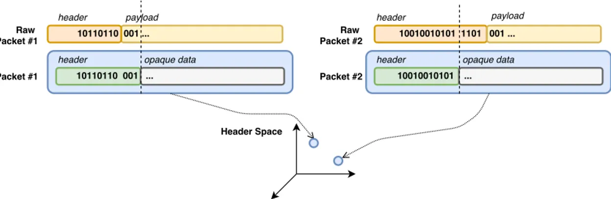
HSA relies on a formal model, built as a geometric model, where: • packets are points in a geometric space
• network boxes are transfer functions on the same geometric space 2. Taxonomy
The following taxonomy defines concepts used later:
2.1. header (h). A flat sequence of ones and zeros. It doesn’t necessarily correspond to the packet header, but it could:
• include just a part of the header • include all of the header
• include the header and part of the packet payload: in this case the payload affects packet processing, that might be useful when modelling a Intrusion Detection System
2.2. header space (H). A geometric space, where: • Every point is a header
• A flow is a region in the {0, 1}L space, where L is an upper-bound on the header length
Figure 1. Building a header space
24 4. Header Space Analysis
2.3. wildcard expression (w). A sequence of L bits, where each bit can assume values in {0, 1, x}.
Each wildcard expression corresponds to a hypercube in H. 2.4. flow (f ). A union of wildcard expression
2.5. network box (n). Any possible middlebox inside the network (also called switch). It has external interfaces called ports.
Every port has a unique identifier. A network box is a node that can be modelled using its transfer function, called switch transfer function (T ), that maps header h arriving on port p:
(1) T (h, p) = (h, p) → {(h1, p1), (h2, p2), . . .}
Notice that T depends on input/output port to model port-specific behavior, for example Load Balancing.
2.6. network space (N ). The space of all possible packet headers, localized at all possible input ports in the network, defined as the cartesian product:
(2) {0, 1}Lx{1, . . . , P }
Where {1, . . . , P } is the list of all ports in the network.
Every point in this space represents a packet traversing on a link.
2.7. network transfer function (Ψ). When a packet traverses the network, it is transformed from one point in the network space to another point. The function that describes the operation is protocol-independent and it can be obtained combining all network boxes behavior together we create a composite transfer function describing the overall behavior of the network, called network transfer function:
(3) Ψ(h, p) = T1(h, p) if p ∈ switch1 T...(h, p) if p ∈ switch... Tn(h, p) if p ∈ switchn
2.8. topology transfer function (Γ). Models behavior of links in the network:
(4) Γ(h, p) =
(
{(h, p∗)} if p is connected to p∗ {} if p is not connected
We can apply the following function at each hop, to model a packet that traverses the network:
(5) Φ(.) = Ψ(Γ(.))
2.9. slice transfer function (Ψs). Captures behavior of all rules installed by the
Control Plane of slice S
2.10. permission (P ). A subset of {read(r), write(w)}.
2.11. slice network space (Υ). A subset of the network space N controlled by the slice S.
4. HSA ALGEBRA 25
3. Modelling network boxes with HSA
In this section we’ll use the taxonomy defined above to model some kind of networking devices with HSA, transforming all of them in a single entity called network box, where the difference between them is encapsulated into the transfer function.
3.1. IPv4 Router. A IPv4 Router can be seen as a network box that implements the following main high-level functions:
• Rewrite source and destination MAC address • Decrement TTL
• Update checksum
• Forward to outgoing port Thus the transfer function is:
(6) TIPv4(.) = Tfwd(Tchksum(Tttl(Tmac(.))))
Where:
• Tfwd= {(h,ip_lookup(ip_dst(h)))}, where: ip_lookup(.) : ip_dst → port
• Tmac(.)looks up the next hop MAC address and updates source and destination MAC
addresses •
Tttl(.) =(drop_packet if ip_ttl(h) = 0
rewrite(h, ip_ttl(), ip_ttl(h) − 1) if ip_ttl(h) 6= 0
• Tchksum(.)updates the IP checksum
If we focus just on IP routing, we simplify the model in:
(7) TIPv4(.) = Tfwd(.) = {(h, p1)} if ip_dst(h) ∈ S1 {(h, p2)} if ip_dst(h) ∈ S2 . . . . {(h, pn)} if ip_dst(h) ∈ Sn {} otherwise Where Si is the subnet where the packet should be forwarded.
3.2. Firewall. A firewall can be modelled as following: • Extract IP and TCP headers
• Match extracted headers against the wildcard expressions which model Access Control List rules
• If the header matches, forward the relative packet • Otherwise, drop it
3.3. NAT. A NAT can be implemented using rewrite rules in packet headers.
4. HSA algebra
In order to implement algorithms based on HSA framework, the following basic operations on header space H are defined:
26 4. Header Space Analysis
4.1. Intersection. Given two headers, intersection is defined as the following bit-wise op-eration:
0 1 x 0 0 z 0 1 z 1 1 x 0 1 x
Where z means the bitwise intersection is empty. It is an annihilator: if any bit returns z, the intersection of all bits is empty.
4.2. Union. In general, a union of wildcard expressions cannot be simplified. This is why a header space is defined as a union of wildcard expressions.
However, there are some specific cases where it can be simplified: (8) 1011xxxx ∪ 1011xxxx = 1011xxxx1010xxxx ∪ 1000xxxx = 10x0xxxx
4.3. Complementation. The complement of header h is the union of all headers that do not intersect with h.
Example:
(9) (01011xxx)0=1xxxxxxx ∪ x0xxxxxx ∪ xx1xxxxx ∪ xxx0xxxx ∪ xxxx0xxx 4.4. Difference. The difference is defined using complement and intersect operations:
(10) A − B = A ∩ B0
It can be used to check if one header is a subset of another:
(11) A ⊆ B ⇔ A − B = ∅ Example: (12) 101xxx0x − 01011x0x = 101xxx0x ∩ (1xxxxxxx∪x0xxxxxx∪xx1xxxxx∪xxx0xxxx∪xxxx0xxx∪xxxxxx1x) =101xxx0x ∪ 101xxx0x ∪ 101xxx0x ∪ 1010xx0x ∪ 101x0x0x ∪ ∅ =101xxx0x ∪ 101xxx0x ∪ 101xxx0x ∪ 1010xx0x ∪ 101x0x0x In this case 101xxx0x is not a subset of 01011x0x.
5. Reachability use-case
One common networking and security problem is nodes reachability. In particular, in security, absence of reachability could mean:
• One or mode nodes have been compromised
• Flow tables are altered and don’t work anymore as designed
• One or more applications have injected rules into the system that affects communication • A denial-of-service attack is in progress
Thus, reachability check is a great use-case for our domain of interest, because it allows us to face a large class of security problems.
The reachability function R between a and b is:
(13) Ra→b=
[
a→b paths
{Tn(Γ(Tn−1(. . . (Γ(T1(h, p))))))}
6. HSA ISSUES 27
• For each path a → b the transfer functions along the path are: T1, T2, . . . , Tn−1, Tn
• Γ functions are needed to compute which is the input port of the next transfer function that is linked with the output port returned by the previous transfer function
The result is a union of wildcard expressions that describe which headers can reach from a to b.
If the result is empty (∅), it means there aren’t any paths that can flow packets from that source to that destination with the given network topology.
6. HSA issues
Header Space Analysis has been developed without considering the dynamic networking needs of SDN.
In fact HSA is unable to stay in sync with the network state incrementally, but instead it needs to recompute all transformations every time network changes. This means it doesn’t scale well with typical SDN lifecycle operations.
CHAPTER 5
NetPlumber
1. Plumbing Graph
NetPlumber[4] is a verification tool based on Header Space Analysis that provides real-time model-based policy checking for dynamic networks.
NetPlumber registers all possible paths of flows through the network in a graph, called Plumbing Graph:
Figure 1. Plumbing Graph
30 5. NetPlumber
Where:
• A rule node represents the rules in the network. A rule is a OpenFlow-like tuple (match, action) and it can forward, rewrite, encapsulate or decapsulate incoming pack-ets. In fact, every rule has:
– A match wildcard expression: used to match incoming flow
– A set of in-ports: used to select which input traffic should be considered or ignored
– A out-port: used to propagate traffic to the next hop
– A rewrite wildcard expression used to perform changes in the flow that passes through the rule
• A next-hop dependency from node A to B represents a link from rule A’s network box to rule B’s network box
• Forwarding rules have priorities. A intra-table dependency is a way to represent priority between rules of the same table and thus which should be considered first when flows comes into the table
• A source node is a node capable to generate flow. This flow generator can be used to propagate flow in rule nodes of the Plumbing Graph, useful to check whether policies and assertions are met
• A sink node is the dual of a source node. It generates sink flow which traverses the Plumbing Graph in the reverse direction. When reaching a rule node, a sink flow is processed by the inverse of the rule. sink nodes don’t increase the expressiveness of NetPlumber but can be used to optimize or simplify some policies
• probe nodes are used to check policy or invariants. Typically they process flow coming from sink nodes or source nodes and check the path and header of the received flows for violations of expected behavior. The policies and assertions are declared using a language called Flowexp
2. Sync with SDN
One of the main reasons because NetPlumber is very suited for SDN is that it can easily respond to SDN events:
SDN NetPlumber
Flow-rule added in a network box Add rule node and potentially change intra-table dependencies and next-hop dependencies
Flow-rule deleted in a network box Delete rule node, associated intra-table dependen-cies
network box added Plumbing Graph remains unchanged network box removed Delete all rule nodes of the relative table
Link added Add next-hop dependencies between rule nodes with ports affected by the link
Link removed Remove relative next-hop dependencies between af-fected rule nodes
3. Policy check
NetPlumber uses source nodes (or sink nodes) to generate flow, probe nodes to get the generated flow and check conditions.
4. REACHABILITY CHECK USE-CASE 31
A probe node is configured with:
• A filter Flowexp: used to decide which flows should be considered • A test Flowexp: used to test whether the policy is met
Conditions and filters are declared in probe nodes with a language called Flowexp Lan-guage, a Domain Specific Language capable of expressing policies and invariants.
Flowexp Language is a regular expression language designed to check constraints on the history of flows received by probe nodes.
The following table will show the BNF syntax of Flowexp Language: Constraint → True | False
| !Constraint
| (Constraint | Constraint) | (Constraint & Constraint) | PathConstraint
| HeaderConstraint PathConstraint → list(Pathlet)
Pathlet → Port Specifier [p ∈ {Pi}]
| Table Specifier [t ∈ {Ti}]
| Skip Next Hop [.]
| Skip Zero or More Hops [.∗] | Beginning of Path [∧] | End of Path [$]
HeaderConstraint → Hreceived∩ Hconstraint |
Hreceived⊂ Hconstraint | Hreceived= Hconstraint
First production rule (Constraint) gives us the possibility to create composite rules starting from simple constraints and combining them into more complex rules.
Second production rule defines what is the main content of a Flowexp: an ordered list of elementary building blocks called pathlets.
A pathlet is a way to specify constraints on the path taken by a flow. pathlets are sequentially checked and if a constraint fails, all the Flowexp fails.
Third production rule (PathConstraint) defines how a pathlet can be made: • Port Specifier: Constraint on which port the flow should pass through • Table Specifier: Constraint on which table the flow should pass through • Skip Next Hop: Don’t apply any constraint on the next hop in the flow’s path • Skip Zero or More Hops: Same as Skip Next Hop but with different cardinality • Beginning of Path: Constraint that specifies the flow should begin its path with that
pathlet and thus next flow’s hop should match the next pathlet
• End of Path: Constraint that specifies the flow should end its path with that pathlet and thus there aren’t any flow hops left
Last production rule (HeaderConstraint) defines constraints on the packet’s content of in-terest (called header in HSA and NetPlumber).
As we’ll see in the next chapter, that language has been mapped into ONOS in order to allow ONOS applications to create flow expressions based on SDN terms. The system will, underneath, translate SDN terms into respective NetPlumber terms.
4. Reachability check use-case
In previous sections NetPlumber framework and relative abstractions have been intro-duced.
32 5. NetPlumber
Now we’ll try to model a Reachability Check Policy with NetPlumber.
The reachability problem from node A to node B can be formulated as: “there should exist some flow that can travel from node A to node B”.
A possible solution is to use:
• A source node that generates a wildcarded flow at each of node A ports
• A source probe node connected to destination port of B with the following condition: (14) ∃f : f.path ∼ [∧(p ∈ {P1, P2, . . . , Pn})]
CHAPTER 6
Model Checking Service
1. Vision
In the last chapters, we’ve seen many security issues related to the current state of SDN plat-form.
In fact there are a lot of threats regarding vulnerabilities or weak designs that could lead to attacks and exploitation activity.
However, let’s try to analyse those problems from a different perspective. Instead of focusing on vulnerabilities or weaknesses, let’s focus on the consequences and the effects. Let’s try to answer to the question “What happens if vulnerability is exploited and attack succeeds?”, instead of “How can I recognize every vulnerability and attack surface?”
This vision puts us in an abstract conceptual space suitable for the system that we want to realize, without having to consider every single source of potential security issues, but instead focusing on side-effects.
2. Goals Let’s define some high-level concrete goals: 2.1. The development process.
We’ve chosen an incremental and model-driven development process.
In the first iteration we want to build a basic artifact, with at least the Case Study working, while keeping the system open for extension, in order to implement more case studies in possible later works.
2.2. Think about problems, not solutions.
The purpose of this thesis is also to define a generic framework to face up new security problems in SDN networks, without having to reinvent the wheel every time a new security issue appears.
Since technologies become obsolete, but problems don’t, we want to design abstrac-tion layers to decouple technology-specific parts with technology-independent ones.
Following this idea, we should define:
(1) A formalization of MCS requirements in the section requirements analysis (2) A formalization of MCS problem in the section problem analysis
(3) A formalization of MCS design in the section project 2.3. First things first.
Important things should always have higher priority.
Since we have limited resources, in this thesis we will follow this ordered list of priorities: (1) problem analysis
(2) project
(3) Main abstractions implementation
(4) Implementation of technology-independent parts
34 6. Model Checking Service
(5) Implementation of technology-dependent parts 2.4. Encourage software reuse.
We should use as much as possible existing analysis to popular problems and relative designs. For this reason we’ll use Design Patterns and Best Practices to speed up the development process and to create a better final artifact.
3. Requirements
Let’s try to be our customers and to formulate requirements in a human-language:
Develop a model-checking based policy system, that allows to build a network model and check if relative policies are met.
The model should be kept in sync automatically with the underlying Software Defined Network state, without any manual intervention.
The system should allow to insert parametrized policies to perform checks on the network state.
They should be inserted manually, by human operators called Network Policy Designers.
When network changes, the changes should be automatically propagated to the underlying network model to the policy system.
In particular when devices, links and interaction rules between them are added, updated or deleted, the network model should reflect changes accordingly. Policy checks should rely just on the model, because network couldn’t be
accessible at the time when check is done and because network probing could lead to false-positives or false-negatives.
Policy checks should be real-time, thus network changes should trigger re-evaluation of existing policies.
The output of policy checks should be available to external operators. Those operators, called Network Policy Response Operator, have different role than Network Policy Designers, in fact they shouldn’t be allowed to add new policies but just check the state of existing policies.
Possibly the system should be flexible enough to add new kinds of policy checks without having to reinvent the wheel, but relying on the existing system, instructing it with the new policy behavior.
In successive steps, during requirements analysis, we’ll try to refine and formalize the requirements defined above.
4. Case Study
In addition to the generic requirements, we want to consider a specific case-study, relevant for as many security aspects as possible.
4. CASE STUDY 35
However, since the model-checking framework is generic, the security expert can place as many different policies as needed, in order to enforce the desired network behavior.
This is just another strength of MCS: it doesn’t implement any policy by itself, but provides the security expert the needed tool to define specific policy to meet specific security needs.
A good case study is a Reachability Check, because it allows to detect a wide range of problems seen in previous chapters:
• Denial-of-Service attacks can be detected with a Reachability Check, because if an intermediate or edge node is under DoS, the nodes under test aren’t reachable. Also the check is real-time, allowing an operator or an automatic system to automatically mitigate the attack as soon as it happens, without any significant delay between the attack and the detection
• SDN Controller attacks that can possibly result in database corruption, changing its perception of the underlying network
• One or more network boxes have been compromised and flow-rules don’t permit nodes reachability anymore
• Attacks that could cause inner loops in the network, difficult to be detected by normal real network scans, can be detected easily with a model-based check
• System resources exhaustion sometimes can lead to DoS and thus can be detected • Some kind of SDN Controller exploitation, when forwarding activity is
compro-mised
What does not detect:
• Malware infection in SDN Controller that leads to some database information leak-age or other side effects that don’t affect nodes connectivity
• Any kind of exploitation both in SDN Controller and network boxes without changing or compromising traffic forwarding
• SBI communication flooding. In that case Plumbing Graph isn’t updated and is unable to detect the attack
36 6. Model Checking Service
5. requirements analysis 5.1. Glossary.
Let’s define meaning of terms used in the requirements above in the following glossary, in order to reduce ambiguity between terms:
Term Synonym Meaning
Model Check Policy Check Check if a single or a set of policies is met
network model Policy Model State of the network model Network State Physical Network State State of the physical network,
how devices are connected and linked, which flow-rules are installed
Software Defined Network SDN Standard name used to re-fer to the underlying network technology
Assertion — Rule about a condition that
the network model can re-spect
Policy — Parametrized set of assertions
that is met if every assertion is evaluated to true
Policy Behavior — The behavior of a policy:
what the policy is supposed to check
Network Policy Designer — Professional role that has responsibility to instantiate policies with custom parame-ters
Network Policy Response
Op-erator — Professional role that can takea look at network model output and policies state
Real-time — Function should take effect
immediately, when needed in-puts and dependencies are available, without having to restart the system or part of it
Policy State Policy output, output of
5. requirements analysis 37
5.2. Requirements Model.
The model formalizes the requirements declared in Requirements section.
This model has been introduced to overcome the necessity to glue the requirements document with the rest of the development process.
In particular:
• We formalize the functional requirements, that will be used later in the use-cases • We formalize the non-functional requirements, that will be used later in the
project
5.3. functional requirements.
functional requirements are the functions of MCS. A function is described by a set of inputs, the behavior and the outputs. In other words, functional requirements are what the system is supposed to do.
This model expresses three main concepts:
• Features: Describe pieces of functional behavior that yield a specific result
• Business Rules: It’s a catalogue of explicit business rules which are required to be implemented within the current project. Business Rules are typically executed during program execution and control the processing of information and transactions. They can be seen as constraints that has to be respected in order to allow correct program execution (in terms of the customer expectations)
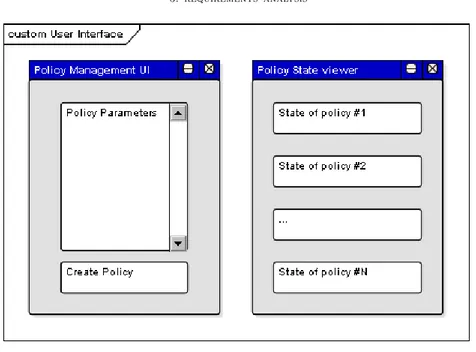
• User Interface: Contain high-level descriptions of end-user visible screens and forms which are required to support the proposed system
38 6. Model Checking Service
5. requirements analysis 39
Figure 3. functional requirements — UI
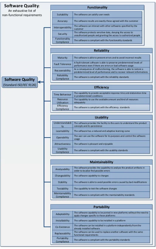
5.4. non-functional requirements.
non-functional requirements specify criteria that can be used to judge the quality of the software artifacts.
In other words, non-functional requirements are how the system does what is supposed to do.
The model below supplies a taxonomy of the available non-functional requirements, as defined in the standard ISO/IEC 9126.
We remind that every well made system should respect all of those requirements, at least with some degree of compliance.
However our particular software MCS pays particular attention to: • Functionality: – Accuracy – Interoperability – Functionality Compliance • Efficency: – Time Behavior • Usability: – Learnability – Operability • Usability: – Analyzability – Changeability – Testability • Portability: – Adaptability – Installability – Co-Existence
40 6. Model Checking Service
Software Quality
(Standard ISO/IEC 9126)
Functionality Suitability The software can satisfy user needs
Accuracy The software results are exactly those agreed with the customer
Interoperability The software can interact with other softwares specified by the customer
Security The software protects sensitive data, denying the access to unauthorized people and granting the access to authorized people Functionality
Compliance The software is compliant with the functionality standards
Reliability
Maturity The software is able to prevent errors and to avoid incorrect results
Fault Tolerance A fault-tolerant software is able to preserve predetermined levels of performance even if there are errors or bad software usage Recoverability As a consequence of malfunctioning, the software is able to restore a
predetermined level of performance and to recover relevant informations Reliability
Compliance The software is compliant with the reliability standards
Efficiency
Time Behaviour The capability to provide acceptable response time and elaboration time in predetermined conditions
Resource Utilisation
The capability to use the available amount and kind of resources adequately
Efficiency
Compliance The software is compliant with the efficiency standards
Usability Understandabili
ty
The software provides the facility to the users to understand the product concepts and its persistence
Learnability The software has a reduced and adaptive learning curve
Operability The user can use the software for its purposes and control the software usage
Attractiveness The software is pleasant and enjoyable
Maintainability
Analyzability The software provides the capability to analyze the product artifacts in order to localize find possible errors
Changeability The software capability to changes
Stability The software is able to avoid possible errors caused by bad modifications
Testability The capability to test the software changes
Portability
Adaptability The software capability to be ported in new platforms without the need to apply changes specific to those platforms
Installability The software capability to be installed in a platform
Co-Existence The software can be installed in a platform independently from the already installed software
Replaceability The software can be used to replace another software with the same functional requirements Maintainability
Compliance The software is compliant with the maintainability standards Usability
Compliance The software is compliant with the usability standards
Portability
Compliance The software is compliant with the portability standards
Software Quality
:An exhaustive list of non-functional requirements
6. use-cases 41
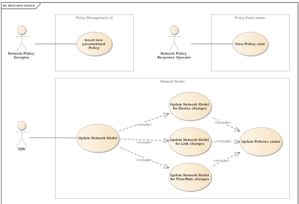
6. use-cases
The use-case model is a catalogue of system functionality described using UML use-cases. Each use-case represents a single, repeatable interaction that an actor experiences when using the system.
actors are the users of the system being modeled. Each actor will have a well-defined role, and in the context of that role have useful interactions with the system.
A person may perform the role of more than one actor, although they will only assume one role during one use-case interaction. An actor role may be performed by a non-human system, such as another computer program.
Figure 5. use-cases They involve the following actors:
42 6. Model Checking Service
7. domain model
The domain model is a view of all the objects that make up an area of interest, and their relationships. It is used here to capture the significant objects within MCS system:
8. problem analysis (logic architecture) 43
8. problem analysis (logic architecture)
The logic architecture shows the logical structure and interaction between the system components.
Let’s start considering the artifacts coming from the requirements analysis: • use-cases
• domain model
The functional requirements defined from those models are now considered to start defining what’s the system architecture from a logical point of view.
The following UML Class diagrams show the structure of main MCS components. MCS structure can be seen as union of four subsystems:
• UI: Permit user to interact with MCS
• Services: Expose operations and MCS functionality to UI
• Operations: Map incoming requested operations into appropriate business logic, that change or query the network model
• network model: Model-checking abstraction, that allows to manipulate the model with abstract terms and concepts, decoupled from the underlying technology. It also allows to define policies that check model properties
8.1. UI Structure.
44 6. Model Checking Service
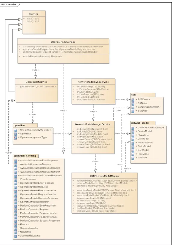
8.2. Services Structure.
8. problem analysis (logic architecture) 45
8.3. Operation Handling Structure.
46 6. Model Checking Service
8.4. Operation Data Types.
8. problem analysis (logic architecture) 47
8.5. network model Data Types.
48 6. Model Checking Service
8.6. SDN Data Types.
8. problem analysis (logic architecture) 49
8.7. Execute-Operation Interaction.
The following UML sequence diagram shows the basic interaction flow when a Network Policy Designer triggers an Operation to create a new Policy:
50 6. Model Checking Service
8.8. Show-Policy-State Interaction.
In the interaction to show policies state, we’ve decided to stay as much generic as possible, since the solution details will be defined in later steps:
8. problem analysis (logic architecture) 51
8.9. network model Interaction.
When there are changes in the SDN, the network model should be kept in sync with the changes. The following interaction diagram shows an example of synchronization, when a SDN element is added and the change should be propagated to the model (the other interactions, like remove and change, are very similar):
52 6. Model Checking Service
8.10. Check-Reachability Interaction.
The following interaction example shows how a “Check Reachability” policy is created and added to the network model:
Figure 17. logic architecture — Interaction — Check Reachability
9. Abstraction Gap
The Southbound Interface of choice will be OpenFlow. This seems to be a reasonable choice, since it’s the precursor of dynamic networks and it’s the most widespread technology for SBI.
ONOS will be the SDN Controller because it’s production-ready and provides all the needs for our proof-of-concept. Underlying network will be simulated using Mininet. It allows to work on different and custom network topologies.
NetPlumber has been shaped for SDN, thus it is particularly suited for implementing un-derlying model-checking mechanisms in our domain of interest.
11. project 53
Figure 18. Reference Platform
Thus, from now on, we will focus on those technologies, while trying to be as much generic as possible.
10. Risk Analysis
The abstraction gap between the problem and the Reference Platform chosen above is sustainable.
11. project
In this step we introduce technology-specific solutions, in particular: • ONOS will be used as SDN solution
• NetPlumber graph (called Plumbing Graph) will be used to implement the net-work model
11.1. Services Structure.
The project structure of the Service subsystem starts from the logic architecture and applies the following changes:
• UserInterfaceService is abstract, the concrete implementation (called ONOSUserInterfaceService) is the one relying on HTTP communication proto-col, used by ONOS
• Services don’t work with abstract SDN and network model data, but instead with ONOS network elements abstractions and Plumbing Graph nodes representation, re-spectively
54 6. Model Checking Service
11. project 55
11.2. Operation Handling Structure.
It’s generic, since it doesn’t depend on particular technologies chosen. The structure is the same as defined in logic architecture.
56 6. Model Checking Service
11.3. Operation Data Types.
11. project 57
11.4. network model Structure.
58 6. Model Checking Service
11.5. SDN Data Types.
SDN data types are realized with ONOS respective data types.
In fact ONOS provides a subsystem called Device Subsystem, that is responsible for dis-covering and tracking the devices that comprise the network, and for enabling operators and applications to control them.
Figure 23. project — Structure — SDN Data Types
ONOS will then map the defined data types with the underlying network, to keep the state consistent. In our case with OpenFlow data types:
DeviceManager OpenFlowDeviceProvider
Device OpenFlowSwitch
DeviceId / ElementId Dpid
11. project 59
11.6. UI Interaction.
The chosen solution for User-Interface is the ONOS Web UI. It relies on modern technologies like Angular 2 to reduce the abstraction gap between the client technology and modern UI needs, in term of changes reaction and client structure.
Interactions between client and server follow the pattern request / response, thus they’ll use the HTTP protocol, designed to handle that interaction pattern well.
UI updates need to be reactive, thus we will use Web Sockets as underlying communication technology.
11.7. Check-Reachability Interaction.
Considering the Check Reachability case-study, the main interactions are:
60 6. Model Checking Service
12. Implementation
Considering previous artifacts defined in the MCS project, we’ve successfully implemented the Model Check Service.
To get a copy of the source code and relative documentation, ask the author at molari dot alessandro at gmail dot com.
13. Tests
Core parts of MCS have been tested using jUnit testing framework. Tests are organized in:
• 60 integration tests: to test interaction between MCS and the underlying Net-Plumber service
• 18 unit tests: to test single isolated functionality of critical parts
For more details on tests structure and implementation, you can take a look at: https: //github.com/alem0lars/mcs/tree/master/src/test/java/me/alem0lars/mcs.
14. Demo
A virtual machine called MCS VM has been created. It features: • A working instance of ONOS
• Networking based on Mininet
• Customized utility scripts to interact with ONOS and perform deployment of MCS To get a copy, ask to molari dot alessandro at gmail dot com.
To uncompress it run: unzip mcs-vm.zip
Now you can import the OVA file in VirtualBox. The following ports need to be available:
• 22to connect to VM via SSH • 8181to access the Web UI
So, if network interface is a NAT, you need to configure port forwarding accordingly. You also need to get a copy of MCS at: https://github.com/alem0lars/mcs. Build the project to generate the application package.
Now you can deploy the application into the ONOS instance available in the MCS VM. Here are some useful commands:
• Build ONOS:
cd $ONOS_ROOT && ./tools/build/onos-buck build onos --show-output • Build ONOS internal test, to check the installation works correctly:
cd $ONOS_ROOT && ./tools/build/onos-buck test • Start ONOS:
cd $ONOS_ROOT && ./tools/build/onos-buck run onos-local -- clean debug • Attach to the Apache Karaf console of ONOS:
cd $ONOS_ROOT && ./tools/test/bin/onos localhost • Start mininet:
sudo mn --controller=remote --topo=linear,10 Where:
– –controller=remote means that mininet OpenFlow nodes should use be con-nected to an external controller (with default port)
14. DEMO 61
14.1. Results. The MCS reachability check has been run in a linear topology with four switches and four hosts: The kind and size of topology chosen don’t affect the test, so we’ve decided to keep it as much simple as possible:
Figure 25. SDN Data Plane topology First of all, we need to install the MCS application:
Figure 26. Install MCS application Now the MCS bundle has been installed and can be activated:
62 6. Model Checking Service
Figure 27. Activate MCS application
ONOS recognizes that MCS defines a custom Web UI, so it asks to enable it:
Figure 28. Enable MCS Web UI The MCS UI is available in the Model Checking tab:
14. DEMO 63
Figure 29. MCS UI “Model Checking” tab
The UI is automatically mapped with the predefined operations that MCS allows.
In fact, when opened, it shows the available operations, in this case Check Reachability:
Figure 30. Model Check operations UI
64 6. Model Checking Service
In the example we’ve started MCS with devices and links already added, but without any flows installed.
This doesn’t affect solution generality, and also shows how NetPlumber and MCS can easily adapt when underlying network changes.
The following logs show the startup process, that involves external dependencies to be started just before the start of MCS components:
2017-10-31 14:47:22,846 |
Starting NetPlumber server ... bound to ‘0.0.0.0:9000‘
with wildcard size of‘224‘ using log configuration at ...
2017-10-31 14:47:23,300 | Started OSGi component ...
After components have been started and activated, the MCS service called NetPlumberSyncManagerwill perform initial synchronization of SDN devices and links with the Plumbing Graph:
2017-10-31 14:47:23,303 |
Performing initial NPG synchronization 2017-10-31 14:47:23,310 |
Synchronizing NPG: ‘of:0000000000000003‘ with ports=‘[1, 2, 3]‘ added ==> adding ‘Table{id=1, ports=[1, 2, 3]}‘ to NPG 2017-10-31 14:47:23,316 |
Synchronizing NPG: ‘of:0000000000000004‘ with ports=‘[1, 2]‘ added ==> adding ‘Table{id=2,ports=[4, 5]}‘ to NPG 2017-10-31 14:47:23,321 |
Synchronizing NPG: ‘of:0000000000000001‘ with ports=‘[1, 2]‘ added ==> adding ‘Table{id=3,ports=[6, 7]}‘ to NPG 2017-10-31 14:47:23,326 |
Synchronizing NPG: ‘of:0000000000000002‘ with ports=‘[1, 2, 3]‘ added ==> adding ‘Table{id=4, ports=[8, 9, 10]}‘ to NPG 2017-10-31 14:47:23,331 | Synchronizing NPG: Link{src=of:0000000000000003/3, dst=of:0000000000000004/2, type=DIRECT, state=ACTIVE, expected=false} added
==> adding ‘Link{src_port=3 <-> dst_port=5}‘ to NPG 2017-10-31 14:47:23,339 |
14. DEMO 65 Link{src=of:0000000000000002/3, dst=of:0000000000000003/2, type=DIRECT, state=ACTIVE, expected=false} added
==> adding ‘Link{src_port=10 <-> dst_port=2}‘ to NPG 2017-10-31 14:47:23,342 | Synchronizing NPG: Link{src=of:0000000000000002/2, dst=of:0000000000000001/2, type=DIRECT, state=ACTIVE, expected=false} added
==> adding ‘Link{src_port=9 <-> dst_port=7}‘ to NPG 2017-10-31 14:47:23,344 | Synchronizing NPG: Link{src=of:0000000000000004/2, dst=of:0000000000000003/3, type=DIRECT, state=ACTIVE, expected=false} added
==> adding ‘Link{src_port=5 <-> dst_port=3}‘ to NPG 2017-10-31 14:47:23,347 | Synchronizing NPG: Link{src=of:0000000000000003/2, dst=of:0000000000000002/3, type=DIRECT, state=ACTIVE, expected=false} added
==> adding ‘Link{src_port=2 <-> dst_port=10}‘ to NPG 2017-10-31 14:47:23,350 | Synchronizing NPG: Link{src=of:0000000000000001/2, dst=of:0000000000000002/2, type=DIRECT, state=ACTIVE, expected=false} added
==> adding ‘Link{src_port=7 <-> dst_port=9}‘ to NPG
66 6. Model Checking Service
Figure 31. Plumbing Graph synchronized with SDN topology
The following logs show the client asked to MCS what are the available operations that can be performed, and the server responded with “Check Reachability” operation:
2017-10-31 14:47:29,137 |
Processing request: operationDetailsRequest 2017-10-31 14:47:29,138 |
Providing operation response for Optional[CheckReachabilityOperation{
fields={name=Check Reachability,
description=Check the reachability between two nodes, id=621fe6b0-c32a-47c3-949a-c7714fbd8fe2}}]
2017-10-31 14:47:29,196 |
Sending response: operationDetailsResponse
Let’s try to submit a new reachability check between devices of:1 at port 1 and of:4 at port 4, so basically we’re checking if host 1 can communicate with host 4 :
14. DEMO 67
Figure 32. Check Reachability operation parameters
In the UI the user can insert the ONOS devices and ports that should be checked whether they’re reachable or not.
In particular the user reasons in terms of SDN concepts and not with NetPlumber concept. This is the result of MCS abstractions layers, defined to hide internal interaction details to the user, so if the internal model-checking framework changes, the user experience isn’t affected at all.
When the user presses the arrow button, MCS adds needed source nodes and source probe nodes needed to perform reachability check and the underlying NetPlumber daemon updates the probes state every time Plumbing Graph changes:
2017-10-31 14:48:08,581 |
Linking Source Node to NPG: Link{src_port=11 <-> dst_port=6} 2017-10-31 14:48:08,590 | Synchronizing NPG: Adding SourceNode{ ports=[11], HeaderSpace{ wildcards=[MatchWildcard{bits=xxxxxxxx..., size=224}], diff=[[]]}} 2017-10-31 14:48:08,603 |
Linking Source Probe Node to NPG: Link{src_port=12 <-> dst_port=4} 2017-10-31 14:48:08,606 |
Synchronizing NPG:
Adding SourceProbeNode{ ports=[12],
68 6. Model Checking Service probe_type=ProbeType{label=existential}, filter=BooleanFlowExpression{value=true}, test=PathFlowExpression{ pathlets=[LastPortsPathlet{ ports=[PortId{device=of:0000000000000001, port=1}]}]}}‘
2017-10-31 14:48:08,628 |Sending response: performOperationResponse
Right after adding source probe node for reachability check, we can see the condition isn’t met, since there aren’t any flow-rules and thus rule nodes:
2017-10-31 14:48:08,624
Existential Probe 2 Activated after event Start Source Probe: Started in False State
Now let’s add flow-rules that allows devices to communicate through the established links:
2017-10-31 14:49:02,958 | Synchronizing NPG: FlowRule{ id=6f0000302f74d4, deviceId=of:0000000000000004, priority=10, selector=[IN_PORT:2, ETH_DST:36:A7:89:EB:C0:E2, ETH_SRC:72:3A:B9:F8:00:AB], treatment=TrafficTreatment{immediate=[OUTPUT:1], deferred=[], transition=None, meter=None, cleared=false, metadata=null}, tableId=0, created=1509457742870, payLoad=null} added ==> adding RuleNode{ table_id=2, index=-1, in_ports=[4, 5], out_ports=[4], match=01001110,01011100,10011101,00011111,00000000, 11010101,01101100,11100101,10010001,11010111, 00000011,01000111,xxxxxxxx,xxxxxxxx,...} to NPG 2017-10-31 14:49:02,976 | Synchronizing NPG: FlowRule{ id=6f000004381f02, deviceId=of:0000000000000001,
14. DEMO 69 priority=10, selector=[IN_PORT:1, ETH_DST:36:A7:89:EB:C0:E2, ETH_SRC:72:3A:B9:F8:00:AB], treatment=TrafficTreatment{immediate=[OUTPUT:2], deferred=[], transition=None, meter=None, cleared=false, metadata=null}, tableId=0, created=1509457742861, payLoad=null} added ==> adding RuleNode{ table_id=3, index=-1, in_ports=[6, 7], out_ports=[7], match=01001110,01011100,10011101,00011111,00000000, 11010101,01101100,11100101,10010001,11010111, 00000011,01000111,xxxxxxxx,...} to NPG 2017-10-31 14:49:02,979 | Synchronizing NPG: FlowRule{ id=6f0000eaafcfe5, deviceId=of:0000000000000004, priority=10, selector=[IN_PORT:1, ETH_DST:72:3A:B9:F8:00:AB, ETH_SRC:36:A7:89:EB:C0:E2], treatment=TrafficTreatment{immediate=[OUTPUT:2], deferred=[], transition=None, meter=None, cleared=false, metadata=null}, tableId=0, created=1509457742877, payLoad=null} added ==> adding RuleNode{ table_id=2, index=-1, in_ports=[4, 5], out_ports=[5], match=01101100,11100101,10010001,11010111,00000011, 01000111,01001110,01011100,10011101,00011111, 00000000,11010101,xxxxxxxx,...} to NPG 2017-10-31 14:49:02,989 |
70 6. Model Checking Service Synchronizing NPG: FlowRule{ id=6f0000a344c5c7, deviceId=of:0000000000000002, priority=10, selector=[IN_PORT:2, ETH_DST:36:A7:89:EB:C0:E2, ETH_SRC:72:3A:B9:F8:00:AB], treatment=TrafficTreatment{immediate=[OUTPUT:3], deferred=[], transition=None, meter=None, cleared=false, metadata=null}, tableId=0, created=1509457742865, payLoad=null} added ==> adding RuleNode{ table_id=4, index=-1, in_ports=[8, 9, 10], out_ports=[10], match=01001110,01011100,10011101,00011111,00000000, 11010101,01101100,11100101,10010001,11010111, 00000011,01000111,xxxxxxxx,...} to NPG 2017-10-31 14:49:02,993 | Synchronizing NPG: FlowRule{ id=6f0000aef00501, deviceId=of:0000000000000001, priority=10, selector=[IN_PORT:2, ETH_DST:72:3A:B9:F8:00:AB, ETH_SRC:36:A7:89:EB:C0:E2], treatment=TrafficTreatment{immediate=[OUTPUT:1], deferred=[], transition=None, meter=None, cleared=false, metadata=null}, tableId=0, created=1509457742881, payLoad=null} added ==> adding RuleNode{ table_id=3, index=-1, in_ports=[6, 7], out_ports=[6], match=01101100,11100101,10010001,11010111,00000011, 01000111,01001110,01011100,10011101,00011111,