Chapter 8
Modelling of foam fluid dynamics
8.1 Introduction
The unfoamed cream present in an aerosol can is called aerosol whipping cream. Before the cream is introduced inside the can it is subject to some treatment, like UHT to sterilise and extend the shelf life of the product. After all the specific treatments, the cream is aseptically inserted into the can, which is then closed with a valve. Finally, the propellant, usually nitrous oxide, is added to the can via this valve avoiding excessive pressure in the can. The solubility of N2O is approximately 50 times that of air. Owing to the high pressure inside the can (4-9 bar) the propellant gas is largely dissolved in the cream [Vuozzo D., 2005]. The amount of gas dissolved in the emulsion is linked to the amount of gas present in the headspace of the can and, therefore, to the pressure in the can. Normally then, before use, it is recommended that the can be shaken to avoid possible inhomogeneities that might be present in the cream. By opening the valve a local pressure drop is created between the inner and the outser part of the nozzle (figure 8.1).
This generates a flow due to the pressure drop and causes foam formation and bubble growth. The amount of gas dissolved in the cream influences the bubble size and consequently the overrun of the foam as well as the appearance. This chapter describes the fluid dynamics of the foam, a heterogeneous system made by emulsion and gas cells, paying particular attention to the flow inside a nozzle. The model shown in this chapter is the schematic representation of an aerated emulsion stored in a can, such as cold whipped cream, extruded under pressure drop, thanks to two different commercial nozzles. The flow behaviour is described by solving momentum balance equations and the simulations, based on rheological properties previously determined, allowed a predictive evaluation of emulsion performance as a function of rheological properties and operating conditions.
8.2 Modelling of foam fluid dynamics
The analysed system is composed of a can having a fixed volume (approximately 400 ml) connected to a nozzle where the emulsion flows while being excited. The nozzle is usually covered by an additional element, the actuator, which gives a specific shape to the extruded products and, therefore, affects the foam flow. The can is typically filled with, approximately, 250 g of liquid emulsion containing a gas, like nitrous oxide, partially dissolved in the liquid and partially dispersed as small bubbles. Thus the fixed volume of an aerosol can is occupied by a volume of cream and a headspace with gas. The pressure in the can is a measure for the number of moles gas, and thus the mass of gas, present in the headspace. When the total mass of gas dissolved in the cream is known, the mass of gas dissolved in the cream can be calculated. Then, since air is approximately 50 times less soluble than nitrous oxide, it seems justified to neglect the solubility of air in the cream. When the nozzle is opened, the foam, being at higher pressure than the ambience, flows outside and, owing to the gas cell expansion, a density change occurs along the nozzle. According to this simplified description of the physical system, the tin can be considered as a reservoir having spatial uniform properties, changing only with time owing to the reduction of both gas and liquid amount, therefore only the flow inside the nozzle and actuator has to be described, whilst the can has to be considered only in the boundary conditions. To account for the foam density change during extrusion through the nozzle, owing to the gas expansion, the single bubble growth was analysed by a “local” momentum balance at the gas/liquid interface, describing the matrix as a viscoelastic liquid. Starting from this “microsystem” (see chapter 2), macroscopic properties, such as void fraction, were computed and used to describe the “macroscopic” foam flow.
8.2.1 Single bubble model
Single cell growth is driven by the pressure difference existing between the cell and the external ambience, but it is limited by bulk properties of the viscoelastic medium and by interfacial properties of the emulsion layer. The dimension change, therefore, can be evaluated by solving a mechanical problem involving the momentum balance equation where the emulsion rheological properties are described by a proper constitutive equation and the interfacial stresses are included. A single spherical bubble at rest, having internal pressure PG and radius R (20 μm was assumed as initial value), surrounded by an infinite mass of fluid, was considered (Figure 8.2).
Figure 8. 2 – Gas- bubble-liquid matrix system
According to chapter 2 and Bird et al. [Bird, 1977], the dependence on time was inserted and the spherical coordinates assumed with respect to the bubble centre and a purely radial flow. Thus, the momentum balance equation, referring to an infinite spherical shell, reads:
∫
∞ ∞ − − − = + 2 G R rr dr r 3 R 2 P P R 2 3 R R τ ρ ρ σ ρ & && (8.1) rrτ being the only non-zero component of the stress tensor (assuming a zero value at infinite distance from the bubble), σ the surface tension, P∞ the pressure at infinite distance from the
bubble, ρ the liquid density, PG bubble pressure described by ideal gas equation. The rheological
term, considering a time-dependent material subjected to a biaxial extension, can be written as [Bird, 1977]:
(
) ( )
( )
( )
∫
∫
−∞ ∞ − − = t 3 3 2 R rr dt' R ' R R ' R ln ' R ' R T , 't t G dr r 3τ & (8.2)therefore a proper definition for the relaxation modulus is necessary. According to Gabriele et al.
P∞ rB
R
modulus can be expressed as :
( )
( )
( )T z 1 t T z 1 1 T A ) T , t ( G − ⎟ ⎠ ⎞ ⎜ ⎝ ⎛ − = Γ (8.3)where z and A represent network extent and strength, respectively, and Γ is the Gamma function. Parameters in eq. 8.3 were determined by performing small amplitude oscillations at different temperatures (see chapter VII). The pressure inside the gas cell, PG, can be described by the ideal
gas law: T R R n P G G G 4 3 3 π = (8.4)
where RG is the ideal gas constant, T the temperature and nG the gas moles inside the cells. Owing
to the gas solubility inside the liquid emulsion, a mass transfer between the two phases establishes when external pressure changes. Assuming that the transport mechanism is fast, compared to the time scale of the process, equilibrium conditions between the liquid and the gas phase hold and they can be described by the Henry’s law [Smith, 1987]:
O N O N Hx P 2 2 = (8.5)
where PN2O is the partial pressure of nitrous oxide in the bubble, H the Henry constant,
O N
x
2 the
N2O mass fraction in the liquid phase. If it is assumed that only nitrous oxide is present in the
system, i.e. neglecting the possible presence of a reduced amount of air entrapped in the bubbles as previously stated, it is found that
G O N P P 2 = O N G G n n 2 , = (8.6 a, b)
furthermore, if the initial amount of N2O is known, the following mass balance holds:
L O N G O N 0 O N2 n 2 n 2 n = + (8.7)
where n0N2O is the initial nitrous oxide amount,
O N G
n
2
, and nL,N2O are the moles of N2O in the gas
and liquid phase, respectively. By coupling the momentum (Eq.8.1) and mass (Eq.8.7) balances with the described auxiliary equations, it is possible to describe the radius evolution as a function of the gas pressure PG, and therefore it is possible to evaluate the pressure as a function of the
foam density, ρ:
( )
ρf
8.2.2 Nozzle fludynamics model
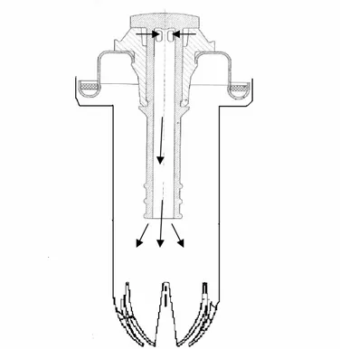
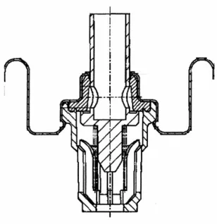
The nozzles and actuators, adopted for soft ice cream extrusion, are shown in Figure 8.3 a-b-c. The nozzle (N1) in figure 8.3 (a) is used also for whipped cream consumption, while the system shown in figure 8.3 (b) (N2) was designed for the purpose. A simplified analysis of the problem was performed assuming the nozzle channel as a cylindrical duct and considering a cylindrical coordinate system (r, z, Θ); because of the angular symmetry only variations along the r and z axes have to be considered and a two-dimensional problem can be studied.
Figure 8.3 (a) – Schematic representation of Nozzle N1. Figure 8.3 (b) - Schematic representation of Nozzle N2.
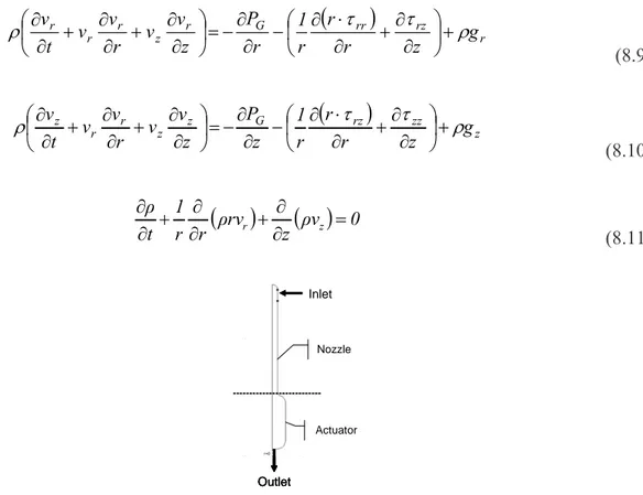
A schematic representation of the considered area (nozzle and actuator) is shown in the Figure 8.4. A pseudo-homogenous approach was used, assuming that gas cells are uniformly distributed inside the liquid, thus an “homogenous” system was considered having effective properties depending on the relative amount of the two phases. This is possible if the time scale of the foaming and transport processes are completely separated. Additional hypothesis are: a constant ratio between gas flow and cream flow that leaves from the can, which corresponds to having completely shaken the can [Vuozzo, 2005], power law fluid, isothermal system, no slip on solid surfaces, and negligible normal stresses. Under these conditions the two components of the continuity equation and the motion equations along r and z, can be written as [Bird et al., 1960]:
(
)
r rz rr G r z r r r g z r r r 1 r P z v v r v v t v ρ τ τ ρ ⎟+ ⎠ ⎞ ⎜ ⎝ ⎛ ∂ ∂ + ∂ ⋅ ∂ − ∂ ∂ − = ⎟ ⎠ ⎞ ⎜ ⎝ ⎛ ∂ ∂ + ∂ ∂ + ∂ ∂ (8.9)(
)
z zz rz G z z r r z g z r r r 1 z P z v v r v v t v τ τ ρ ρ ⎟+ ⎠ ⎞ ⎜ ⎝ ⎛ ∂ ∂ + ∂ ⋅ ∂ − ∂ ∂ − = ⎟ ⎠ ⎞ ⎜ ⎝ ⎛ ∂ ∂ + ∂ ∂ + ∂ ∂ (8.10)(
)
( )
ρv 0 z rv ρ r r 1 t ρ z r ∂ = ∂ + ∂ ∂ + ∂ ∂ (8.11) Outlet Inlet Nozzle Actuator Outlet Inlet Outlet Inlet Nozzle ActuatorFigure 8.4 - Schematic representation of the system
Where ρ is the foam density, P is the pressure, t is the time, vr and vz are, respectively, radial and axial component of velocity vector, τij the non-zero components of the stress tensor.
Foam density is a function of gas pressure according to equation 8.8. Different equations are reported in the literature to evaluate the rheological behavior of a foam as a function of the liquid matrix properties.
the liquid phase, by using proper rules; according to Gardiner et al. (1998), if the liquid viscosity is described by a power law, the same equation holds for the foam by assuming
n n' ; ε k ' k = = (8.12)
being ε the ratio between liquid and foam density, k’ and n’ consistency and flow index of the foam, respectively. Therefore the foam behaviour can be described by the general three-dimensional form of the constitutive relation for a two-parameter power law fluid [Tanner (2000)]:
(
4II)
D ' k τ 2 1 ' n D − − = (8.13)where IID is the second invariant of the rate of deformation tensor, D, and τ is the stress tensor.
During the process the gas escapes from the can together with the emulsion, therefore internal pressure decreases continuously and foam density changes too. The amount of gas and liquid leaving the can is computed at any time from the foam flow rate, Q(t), obtained by integration of the velocity field at the nozzle outlet, L:
( )
t 2 rv(
r,L,t)
drQ R
0
∫
z= π
(8.14)
where vz(r, L, t) is the z component of the velocity vector at nozzle outlet, at time t, and R is the
nozzle outlet radius.
Masses inside the can are computed by simple mass balances on both components, assuming no gas exchange between the liquid phase and bubbles (i.e., neglecting the pressure dependence of the gas dissolved into the liquid):
( )
= −∫
( )
t L L L t m f k Qt dt m 0 0 ρ ( ) (8.15)( )
= −∫
( )
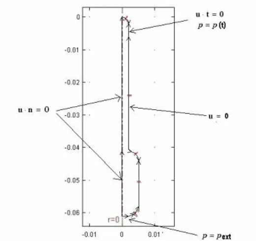
t g g t m g k Qt dt m 0 0 ( ) (8.16)flow and cream flow (k) during the spraying process. Moreover, shaking causes bubble formation in the cream which may affect the state extrusion process and the corresponding overrun. In fact, shaking the system before consumption it is possible to have major overrun and lower residual mass inside the can [Vuozzo, 2005]. Thus, because of the mass change inside the can, the internal pressure and density change too. Finally, the following boundary conditions (Figure 8.5) were adopted:
− axial symmetry;
− no slip on solid surfaces;
− atmospheric pressure at nozzle outlet; − P(t) inside the can at nozzle inlet;
− velocity vector orthogonal to inlet and outlet surfaces.
Figure 8.5 - Boundary conditions for considered system.
8.3 Conclusions
The fluid dynamic behavior of a foam through a nozzle was described by considering the momentum and continuity equations coupled with the proper constitutive relationships describing the foam flow properties.
The system was considered pseudo-homogeneous, using the effective properties, related to the liquid matrix parameters and to the local foam density by proper constitutive relation. The “single bubble” model was considered to have a void fraction degree of foam. In this way it is possible to describe the bubble growth inside a viscoleastic medium and relate the system overrun to the pressure drop. Considering the foam formation process out of the aerosol can, it is important to know the proportion of the gas and cream flow. In this model the ratio between gas and cream flow was assumed constant
with time (k). This hypothesis is plausible because normally the system is completely shaken before use. Finally, knowing the ratio k, it is possible to update all the conditions, like N2O moles or pressure inside the can, thanks to a simple mass balance.
8.4 References
− Bird, R. B., Stewart W.E., and Lightfoot E.N, Transport phenomena, John Wiley and sons, New York, 1960.
− Bird, R.B, Armstrong R.C., Hassager O., Dynamics of Polymeric Liquids, Vol.1, Wiley, New York, (1977).
− Gabriele, D., B. de Cindio, P. D’Antona, Rheologica Acta, 40, 120-127 (2001).
− Gardiner B.S., B.Z. Dlugogorski, and G.J. Jameson, Rheology of fire-fighting foams, Fire Safety J., 31, 61-75, 1998.
− Smith, J.M., H.C. van Ness, Introduction to Chemical Engineering Thermodynamics, McGraw-Hill International Editions (1987)
− Tanner R., Engineering Rheology, Oxford University Press, UK, 2000. − Vuozzo D, Codap Internal report, 2005.
![181Appendix II T [°C] A [Pa·s](data:image/gif;base64,R0lGODlhAQABAIAAAP///wAAACH5BAEAAAAALAAAAAABAAEAAAICRAEAOw==)