25
Chapter 3
3.1 Overview of the chapter
Chapter 3 describes the design phase and realization of three different bioreactors: ILT1, ILT2 and MCmB 3.0. The first 2 devices are realized in order to meet the specifications of a European project called InLiveTox. The third one is designed and realized in order to overcome some restrictions that are correlated to ILT2, as it will be described in next paragraphs. The first part of the chapter is dedicated to the InLiveTox project and the correlated bioreactors. The second part describes the MCmB 3.0 realization.
3.2 InLiveTox Project
The goal of the FP7 InLiveTox project is to develop an improved in-vitro model to study the impact of Nanoparticles (NP) exposure on the body. The use of nanotechnology in consumer and industrial sectors is expected to increase significantly in the future. Nanotechnology is defined as the ability to create and use materials, devices and systems with unique properties at the scale of approximately 1 to 100 nm. Nanotechnology offers society the promise of major benefits, but also raises questions of potential adverse effects. At this particle size, quantum mechanical effects often dominate and surface area per mass is dramatically increased, resulting in materials that exhibit unique physical, chemical, electrical, optical, mechanical and magnetic properties. The challenge for health (and environmental) protection is to ensure that as nanomaterials are developed and use, any unintended consequences of exposures to humans are prevented or minimised. In addition, knowledge concerning how best to apply nanotechnology to detect, monitor, prevent and control is needed. In Europe and in the USA, governments, non-governmental organisations, and others have expressed concern that, with the field of nanotechnology and the number of consumer products incorporating nanomaterials increasing dramatically,
26 in many cases, the safety of these materials has not been demonstrated and there are still a large number of unanswered questions.
In order to understand behaviour and responses of biological systems to nanomaterials, and therefore to manage subsequent risks, it is essential to investigate the hazard (toxicology) of the large number of engineered NP in different formulations and at different points in their life cycle (from production to disposal), in relation to different routes of exposure and different target organs and tissues. The number of experiments therefore required to address such issues is enormous and so it is essential to develop rapid and reliable non-animal models to assess NP hazard
The model developed by the InLiveTox consortium is based on a modular fluidics-based multi compartmental cell culture system – abbreviated ILT in this document. Different tissue models based on human cells are cultured in the compartments of the ILT and are connected via the flow of culture medium through the fluidic system. The ILT is the first step towards a closer model of NP passage through the gastrointestinal (GI) tract, into the blood vessels in the abdomen or viscera and into the liver. Although the scheme described may seems simplistic, it has already been shown that even 2 cell connected culture systems behave in a more physiologically relevant manner than static monocultures [23, 24.]. The aim is to extract the salient features of the gastro intestinal tract (GI) metabolic pathway and include them in the model.
3.2.1 System specification
The ILT system consists of a small number of cell culture compartments linked by a fluidic system. The cell culture compartments allows the culture of different models for human tissues based either on human cell lines, on primary cells or on a mixture of the two. The compartments are designed for the culture of models of the intestinal epithelium, the liver and the vascular endothelium. The fluidic system consists of two independent circuits, one representing the gastrointestinal (GI) tract and the other representing the circulatory (blood) system. The “bloodstream” circuit circulates culture medium in a closed loop, as the GI circuit. It is foreseen that NPs are introduced into the system in the “GI” circuit to
27 model their ingestion. However it is possible to introduce NPs directly into the “bloodstream” circuit.
The two fluidic circuits run either side of the model intestinal epithelium which is supported by a porous membrane such that transport of NPs from one circuit to the other crosses the epithelium. A system to measure the permeability/tightness of the model epithelium is included in ILT so that the contribution of paracellular transport (around the cells) can be estimated and minimized. The ILT system allows culture of the different tissue models within the fluidic circuits for at least 24 hours. Temperature and pH control during this time can be achieved by placing the entire fluidics device inside a CO2
incubator. The ILT system is used to model both NP fate and toxicity. In order to achieve this, both the location of the different NPs in the system at different times are measured as well as a number of toxicological endpoints. Measurements are carried out:
By sampling and analyzing cell culture media from different locations in the system
By sampling and analyzing the tissue models cultured in the different chambers For this reason sampling ports are included, so that small samples of liquids can be removed from the device during cell culture. In contrast, access to the cells of the tissue models may be limited to the removal of samples after the end of the culture period. In addition to the fluidic device and external control and analytic instruments, a number of liquid containers are also associated with the ILT system. These bottles and/or chambers function as reservoirs of the liquids to be used (e. g. cell culture media) as waste containers, as mixing chambers, as gas exchangers. A simplified schematic of a possible ILT configuration is shown in Figure 2.3.
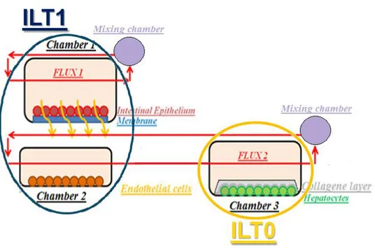
The ILT system is modular so that compartments and fluidics circuits can be combined in different ways in order to simulate different biological models. In order to follow specifications, it was decided to use two different chambers to seed cells. The first one called ILT1 is shared by the intestinal epithelium and endothelial cells. Intestine epithelium is seeded on a microfabricated membrane made by CSEM, the Swiss partner of the project. This device is then placed inside bioreactor. Endothelial cells are seeded on a glass disc
28 and placed in the bottom part of ILT1, described in 3.3. The second bioreactor is represented by MCmBTM [10] chamber that in this document is called ILT0. Figure 3.1 summarizes the situation. The system is connected to a peristaltic pump that in figure 3.1 it is not shown.
Figure 3.1The ILT circuit composed of ILT1 and ILT0 bioreactors
As far as computational modelling concerned , it is well characterized both as regards oxygen transport as well as flow. It is used in several laboratories where it has been tested with different cell cultures. It represents a suitable solution to cultivate hepatocytes because of the low shear stress that can be evaluated on the bottom chamber. ILT0 description is not the aim of this thesis. The need of a slot to place the membrane forces to create an evolution of ILT0 in order to obtain a new fluidic device: ILT1. Before describing ILT1 the micro fabricated membrane will be described because it is an essential and innovative part of the system.
The membrane shown in figure 3.2 is made of a silicon wafer of 14mm X 14mm X 0.39mm, where opened pores are realized by photolithography. Membrane follows an
29 evolution during InLiveTox project. The final version is represented by pore size of 1 μm in diameter with a fill factor of 15%. In order to perform electrical measurements, platinum contacts are deposited on the silicon wafer (two contacts on each side of the chip).
Figure 3.2Micro fabricated membrane used in InLiveTox
In next paragraphs the ILT1 system computational models and in-vitro tests in order to validate them will be described .
3.3 ILT1 Bioreactor
The ILT1 bioreactor is an evolution of the ILT0 system. The specifications to be achieved are:
Possibility to position a square membrane of 14mm X 14mm X 0.39mm. Epithelial cells can be seeded and developed on this support.
Possibility to use two co-current medium flows: one on each side of the membrane. Flows direction has to be longitudinal to the membrane section.
Possibility to insert 4 electrodes and reach the platinum circuit on membrane in order to measure trans epithelial electrical resistance (TEER).
30 The electrodes have to be in dry environment in order to avoid any short circuits,
which could represents a bias in TEER. System has to keep watertight.
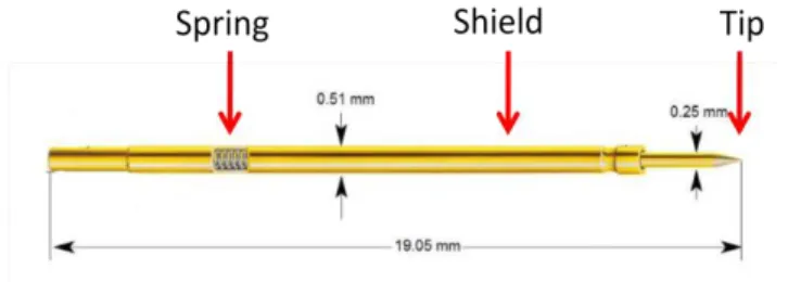
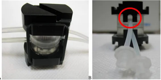
In order to meet these specifications, a new system called ILT1 was developed. As its predecessor, ILT1 is made of Poly di-methyl siloxane (PDMS) because of its auto sealing property, its transparency and malleability. The bioreactor is composed of two units: an upper chamber and a bottom one. A male – female joint permits the two halves to be properly assembled. The bioreactor shape when all its components are correctly joined is a cylinder of 36 mm in height and 27 mm in diameter. The electrodes are small cylinders of 0.51 mm in diameter. They are composed of a cylindrical hollow shield and a movable tip, as it is shown by figure 3.3. A spring positioned in a slot inside the shield allows tip movement on Z-axis in order to avoid any damage when the electrodes touch a rigid surface.
Figure 3.3 Electrodes made by cylindrical hollow shield and a movable tip. A spring allows tip movement along the Z-axis.
In next paragraphs the PDMS chambers and clamp system to keep bioreactor watertight will be described.
3.1.1 Bottom chamber
The bottom unit has a square chamber of 11.5 mm per layer and 11 mm in thickness. This is called wet volume in fluid dynamic science. Glass slides of 13 mm in diameter where cells are seeded can be housed [20] inside this structure. In order to have a dynamic environment an input tube (1 mm inner diameter) and an outlet (2 mm inner diameter) are
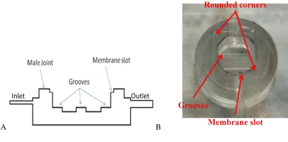
31 placed on opposite sides of the chamber. These connections are placed respectively at 6 mm and 5.5 mm from the bottom of the wet volume. A peristaltic pump forces a medium flow through the chamber inlet tube in order to bring nutrients and stimulate cell proliferation by shear stress. In order to keep laminar flow conditions it is decided the square shape of the chamber was modified. Corners were rounded off intercepting the square shape with a circle of 13 mm in diameter. On the bottom chamber surface three grooves of 3 mm in width and in thickness are realized. The aim of these elements is to reduce the contact surface between the glass slide and PDMS, in order to avoid any sealing phenomena. If scaffolds are used for cell seeding they can be placed on the grooves. In this case the grooves permit some passage of oxygen cells from the bottom side. The upper part of the PDMS chamber is moulded in order to obtain a ring of 3 mm in width and thickness. This represents the male joint which allows connection with upper chamber. On the upper surface a square slot of 14.5 mm slide and 0.3 mm in thickness is moulded. Figure 3.4 represents a section view of ILT1 and a picture of the chamber in PDMS.
A B
Figure 3.4 A: Section view of ILT1bottom chamber. Grooves, membrane slot and male joint are in evidence. B: picture of ILT1 bottom chamber. Rounded corners are in evidence
The membrane can be housed inside this structure. The slot dimensions take in consideration PDMS shrinkage in order to fit membrane specifications. Once the membrane is placed, the upper chamber can be joined with the bottom one. By this way the
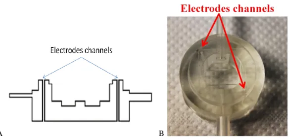
32 membrane will be pressed by the PDMS parts in order to keep it in position and assure a watertight deal between Si-PDMS interfaces. This last point is very important because cells on the membrane have to modulate information between the upper and bottom circuits. The only communication way has to be represented by the cell layer. As a consequence, the Si-PDMS watertightness has to avoid medium flows around the membrane chip instead of crossing its pores. One of the project targets is represented by the possibility to monitor cell on the membrane by Trans Epithelial Electrical Resistance measurements (TEER). The higher is this parameter, the closer are cells in confluent conditions, which represents the systems working point. The EVOM epithelial voltmeter from World Precision Instrument Inc. [24] was the first instrument designed specially to make routine TEER measurements in cell cultures research. In the InLiveTox project the standard set of electrodes that is provided with the EVOM machine is substituted by four electrodes, assembled in 2 individual pairs. Each electrode has to be in contact with a platinum isle linked to an electrical circuit realized on membrane surface. In an electrode pair it is possible to recognize a current emitter and a voltage sensor. On each side of the membrane it is possible to recognize an inner electrical circuit that is in contact with the current emitter and an external one in contact with the voltage sensor. EVOM machine force a current to flow inside the inner circuit, due to the contact with the current emitter electrode. Voltage is measured by EVOM on the other circuit. The same thing happens on the other side of the membrane, Evaluating the voltage difference between the membrane sides and making the ratio with the current that flow in each circuit possible to evaluate the electrical resistance represented by the membrane thickness and the cell layer that is deposed on the porous surface. In order to obtain voltage difference between each circuit and avoid a value influenced by a short circuit between electrodes, it is important to keep dry conditions around the electrodes. To follow this specification channels that cross vertically the PDMS chamber are realized. These channels run parallel to the wet volume and reach the platinum isles on the membrane surfaces. If the PDMS-Si interface is watertight, liquid cannot reach the sensor units. Watertightness is assured by a clamp system which imposes a suitable pressure to avoid any leakage. The clamp system will be described in paragraph 3.1.3. Figure 3.5 A represents the electrodes channels in an ILT1 cross section view. In figure 3.5 B in channels where electrodes are placed are represented.
33
A B
Figure 3.5 A: Section view of ILT1bottom chamber. Electrodes channels are in evidence. B: Picture of electrodes insertion in PDMS chamber
3.1.2 Upper chamber
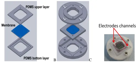
Fewer modifications are necessary in order to develop the ILT1 upper chamber compared to the bottom chamber evolution. The upper chamber has an inlet and an outlet, in order to assure a laminar flow as in the bottom chamber. The wet volume has a cylindrical shape. Its upper surface is moulded in order to obtain a sloping roof. The aim of this structure is to drive out air bubbles. Moreover in order to avoid air bubbles sticking on the bioreactor wall, resulting in a local pressure and then a shear stress increase, inlet (1 mm inner diameter) and outlet (2 mm inner diameter) tubes are placed on two different planes. The offset between inlet and outlet is 1.2 mm. The input tube is placed 6.5 mm in height from the bottom part of the chamber. The higher position of the outlet than the inlet, and sloping roof represents suitable solutions in order to drive out air bubbles from the upper chamber. The cylindrical wet volume projection covers the membrane electrical circuit completely, but it cannot reach the platinum isles. This characteristic is a result of the ILT0 chambers reduction in volume. On the bottom surface of the PDMS unit a ring of 13 mm in diameter and 3 mm in thickness is realized. It represents a female joint to assemble the upper and bottom chamber. Two vertical channels in the upper chamber are realized in order to create a communication between platinum isles on the membrane and the electrodes. Figure 3.6
34 “A” represents a cross section view of the ILT1 upper chamber. In B a picture of the chamber is reported.
A B
Figure 3.6 A: cross section view of the ILT1 upper chamber. Electrode channels, sloping roof and female joint are in evidence. B: picture of chamber
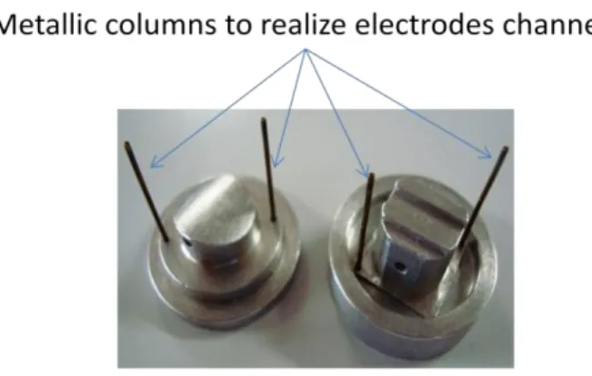
It is possible to insert 4 electrodes in the bioreactor using the vertical channels in the top and bottom parts of the chambers, so keeping the electrodes in dried conditions. ILT1 is made by casting PDMS pre polymer in moulds. The moulds are made of aluminium and are a negative of the chambers, as shown in figure 3.7.
35 Figure 3.7 ILT1 Moulds. Metallic columns used to create electrodes channels during
casting phase are in evidence
In order to realize several bioreactors together a system of flanges where it is possible to house several chamber moulds is used. In comparison with the ILT0 system, ILT1 flanges are reduced in height in order to obtain a good control of ILT1 dimensions. When the PDMS polymer reaches the upper layer of the flanges casting is stopped in order to obtain flat bioreactors on bottom and upper surfaces, avoiding any meniscus, typical of ILT0. As it will be described in next paragraph it is very important to control the chamber height in order to be able to reach the membrane by electrodes of fixed length. Figure 3.8 shows the flanges and bioreactor moulds ready for casting.
36
3.1.3 Clamp system
In spite of having a male-female joint, the watertightness of the system would not be assured without a clamp system in order to impose a suitable pressure to seal PDMS-Si and PDMS-PDMS interfaces. Once assembled, ILT1 is placed between a couple of plastic clamps. These clamps are made by milling. Each surface in contact with the bioreactor has a cylindrical slot to insert the chambers (figure 3.9). The thickness of this slot is not sufficient to impose a compression on bioreactor outlet tubes. Each disc has a couple of teeth that can housed inlet tubes, in order to provide an alignment between chambers (figure 3.9).
A B
Figure 3.9 A: 3D view of a clamp disc. B: section view of a clamp disc. Teeth to house tubes and align chambers are in evidence
Each clamp has electrode holes in correspondence to channels realized in ILT1, in order to create a continuum where a sensor can be inserted vertically. Electrodes upper tips are shielded by a parallelepiped structure in order to protect contacts between sensors and wires that connect to the impedance evaluator machine, called EVOM (paragraph 3.2.1). On the other side electrodes tips are in contact with the membrane surface. The clamps have slots in order to house the parallelepiped structures (figure 3.10). A screw on each clamp allows to maintain a fixed contact between inserts and discs.
37 Figure 3.10 A: upper view of clamp disc. It is possible to see the slot where the electrodes
shield has to be housed B: electrodes shield C: ILT1 bioreactor and clamp system joined by O-rings. Note the screw that keeps the contact between electrodes shield and clamp disc
3.4 ILT2 Bioreactor
ILT1 was evaluated by a number of cell culture experts in the InLiveTox project. The experts pointed out a number of problems with the system. The main concerns were:
Difficulties in membrane manipulation when cells are seeded on membrane. In particular it is not easy to transfer the membrane from a multiwell where the first growth phase occurs, to the bioreactor.
Once placed in its slot on the bottom chamber, the membrane does not remain in a fixed position when the upper chamber is joined with the bottom one. In particular friction between the membrane surface and upper chamber PDMS causes a misalignment between membrane platinum isles and electrode channels.
In some tests a liquid passage from upper chamber to bottom one was pointed out. This represents a problem because in few hours it causes emptying of the upper circuit. In this condition it is impossible to analyse results after 24 hours. This phenomena is not due to leakage, because ILT1 watertightness is assured.
Electrodes are too fragile. It is easy to break them during the insertion phase. The number of units that compose ILT1 circuit causes problems of system
38 In order to solve all problems pointed out by feedback points an evolution of ILT1 is studied. In particular the first three points cited previously resulted in the realization of a new fluidic system: ILT2. PDMS was maintained as the chamber material because of its excellent self sealing properties, but the chamber shape and dimensions are revised and adapted. The ILT2 bioreactor is composed of three units joined together by male female joints. In order to shield the membrane, an holder system is designed. The chip is housed between polycarbonate (PC) discs, to prevent any damage during manipulation. This device is then interposed between the two PDMS chambers. Modifying the bioreactor height, a new clamp system is designed. New electrodes of 0.86 mm in diameter are used in the new ILT2 system, in order to prevent breakage. A plate to place the ILT2 bioreactor and mixing chamber is designed in order to solve the last problem pointed out by partner’s feedback. In next paragraphs the holder system, chambers, clamp system and plate will be described.
3.4.1 Holder system
This new unit is designed in order to solve membrane manipulation problems pointed out by partners. Membrane fragility and difficulties to place it inside the ILT1 slot when cells are seeded on the porous membrane caused problems in the ILT1 assembly phase. The holder system is designed to shield the membrane and permit seeding cells at the same time. Moreover holder dimensions permits to keep membrane in multiwell when cells are seeded. The new system represents a valid device to develop models of barrier tissues, characterized by cells cultivated at a liquid-liquid interface. When the cells form a tight junction barrier layer, the membrane housed in holders is placed in ILT2. In this new bioreactor interaction between PDMS chambers and membrane are avoided, because of PC discs that shield the micro fabricated membrane. The holder system is composed of two PC cylindrical discs. Each element has a diameter of 15 mm, in order to fit the dimensions of a 6 well plate slot. Two discs (upper and bottom holders) are assembled and screwed together in order to have a closed system. the membrane can be housed inside this structure, as described in protocol [Appendix B]. Two PDMS layers of 0.5 mm in thickness compose a protective sandwich around the membrane. The sandwich is then housed in a square slot of 13 mm in wide and 5 mm in thickness realized in the bottom
39 holder. Moreover a slot representing the female joint where placed the male part moulded on upper holder surface is added. PDMS-membrane-PDMS sandwich is compressed by the upper disc, in order to keep the interfaces inside the holder system watertight, thanks to PDMS sealing property under pressure (figure 3.11).
A B C
Figure 3.11 A: Membrane shielded by a pair of PDMS layers. B: sandwich made by PDMS layers and membrane housed in bottom disc slot. C: the upper holder is finally screwed
with the bottom one.
The square slot allows for PDMS deformation due to compression. The central section of the membrane, where pores are realized , is exposed to the outer environment thanks to cavities realized on both discs. In this way cells can be seeded directly on the membrane when it is housed in the holders. A couple of channels cross each holder vertically, to allow insertion of electrodes in correspondence to platinum isles (figure 3.11 C). Once the holder system is assembled, it can be sterilized by gas plasma or with the autoclave, before seeding cells on the membrane. During cells growth the electrodes holes are covered by a biocompatible tape, in order to avoid the possibility that culture medium reaches the membrane isles. The thickness of holder system is less than 3 mm. This parameter permits to use an optical inverted microscope in order to study cells on the membrane and monitor their growth. Once the growth phase is ended, the system can be transfer to the bioreactor.
40 Both discs surfaces that interface with PDMS chambers are characterized by male joint in order to create corresponding male-female joints with both chambers.
3.4.2 Bottom chamber
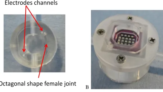
The shape of the bottom chamber is taken from the ILT1 bottom unit. Its thickness is reduced in order to obtain a wet volume equal to the upper chamber. Tube placement is drastically modified in comparison to ILT1. In the ILT1 inlet hole was placed in a higher position than the outlet. This caused problems in order to drive gas bubbles out. In the new version this situation is inverted: the outlet is placed in a higher position than the inlet, in order to create similar conditions to the upper chamber that represents the best solution to drive out gas bubbles. In the design phase the complete revision of the male female joint system of ILT1 was necessary due to the new holder. Firstly the holders have male joints on both interfaces with PDMS chambers. Then in the bottom chamber a slot of suitable shape to house the holder male is realized. In ILT1 male-female joint had a cylindrical shape. In that case the alignment between upper and bottom chambers was at the hands of the operator. Moreover in ILT1, in order to find a good alignment it was necessary to rotate chambers, causing membrane movement. In order to avoid this problem, ILT2 joints have octagonal shape (figure 3.12 A). Moreover two parallel layers in this geometrical form are realized longer than the others, in order to promote assembly in an easy way and force an alignment between chambers and holders (figures 3.12 B).
41
A B
Figure 3.12 A: upper view of ILT2 bottom chamber. B: Bottom chamber and holder system are assembled
Once again it is possible to observe electrodes channels that cross vertically PDMS following a parallel direction to chamber height (figure 3.12 A). They are realized in correspondence to holder holes, so that the electrodes can be easily inserted. Once electrodes are placed inside ILT2 the electrodes are guaranteed to remain dry. Finally watertightness of PDMS-PDMS and PDMS-PC interfaces is guaranteed by the application of a suitable pressure.
3.4.3 Upper chamber
The upper chamber is the most similar part to ILT1. Only a small evolution was needed by this unit. The shape and dimensions are taken from ILT1. A small change is represented by the female joint of octagonal shape in order to house the holder male (figure 3.13). As described for the ILT2 bottom chamber, it is not possible to misalign holders and upper unit because of the unique shape of the joint. The operator has only to take care that both bioreactor inlets are placed on the same side. The upper chamber tubes are placed in the same position as the ILT1.
42
A B
Figure 3.13 A: upper view of ILT2 upper chamber. B: upper chamber, holder system and bottom chamber are joined
The amount of PDMS used to realize chamber is also reduced. In this way the cylinder that constitutes the upper unit of the bioreactor is thinner. This solution permits to save PDMS and give to chamber an higher transparency. However it is not enough to visualize cells with an optical microscope during an experiment, because of the sloping roof presence and chip distance from the optical system. Figure 3.13 B shows ILT2 units joined as described in protocol [Appendix B]. In conclusion it is easier to manipulate ILT2 than ILT1, because of new male-female joint, holder system and its reduced height. The last point forced the choice of electrodes of 18 mm in length and 0.86 mm in diameter (hollow shield part). The length of electrodes is the same for upper and bottom halves because of the decision to design a system where clamp thickness + chamber height is the same for upper and bottom case. Moreover the relative distance between upper chamber outlet and top of PDMS cylinder is reduced, so the clamp system has to be revised in dimensions, in order to avoid tube compression by the clamp disc when the bioreactor is under pressure.
43
3.4.4 Clamp system
The clamp system is composed of two plastic discs that house the bottom and upper chamber respectively as in ILT1. The main modifications are related to the dimensions in order to follow new specifications of ILT2. The slot thickness of the upper clamp is reduced in order to avoid any compression of the upper chamber tube. In ILT1 a couple of teeth per disc aided alignment between chambers and house inlet tubes. In ILT2 the alignment between chambers is due to the male-female joint, so teeth are removed. The operator has to take care that the electrode channels realized in PDMS are aligned to holes created on clamps surface for sensor insertion. Once again electrodes contacts with wires are shielded by a plastic insert (figure 3.14 A). Slots where these parts can be housed are obtained on both clamp discs. In ILT2 a screw is not used in order to keep contact between electrodes shield and clamps. A bar provided by a couple of magnets is placed on the top part of shield, in order to make a sort of clamp system for the insert. (figure 3.14 B) Two magnets per disc are integrated in bioreactor clamp magnets. The alignment between bar magnets and clamp ones permits to obtain a suitable pressure on the electrodes shield, in order to avoid the loss of contact. O-ring are used to connect the clamp discs and impose pressure on ILT2 placed between them (figure 3.14 C).
A B C
Figure 3.14 A: plastic shield that protect contact between electrodes and wires. B: plastic bar with magnets used to keep contact between sensors insert and clamp disc. C: ILT2
44
3.4.5 Plate
In order to solve the problem pointed out by the last point, (Feedback from biologists in section 3.4) a plastic plate (Master plate) is realized where the ILT2 system and mixing chambers can be housed. The assembled bioreactor is housed in a cylindrical slot of 45 mm in diameter and 20 mm in thickness. In order to hold the bottom clamp disc. Mixing chambers are placed in cylindrical slots of 30 mm in diameter and 20 mm in thickness, in order to avoid chambers failing over (figure 3.15 A). Moreover tubes that connect ILT2 to bioreactors where target tissues are seeded could create the same problems pointed out by partners for the ILT1 system. A second plate (Slave plate) is designed in order to house bioreactors with target tissues (figure 3.15 B). It is possible to join the plates by a male female joint created on the bottom side of both units. It should be noticed that, following the idea of modularity, several slave plates can be joined in series because each slave plate supports both kind of joints. A couple of screws assure a fixed contact between plates, in order to manipulate them as one piece (figure 3.15 C).
A B C
Figure 3.15 A: Master plate where bioreactor and mixing chambers slots are in evidence. B: slave plate C: master plate and slave plate are joined
It is easy to transfer the complete system from the laminar hood to an incubator without any risks for cells seeded in bioreactors using the plate system. The reduced distance between system units and mixing chambers permits to reduce tubes length as described in ILT2 protocol. This has two consequences: reduction of circuit volume and problems in
45 managing tubes in incubator. Less culture medium is used than in ILT1, so analyte concentrations are easier to measure. The second point allows operators to set up the system in an easy way and a good space management inside incubator.
3.5 MCmB 3.0
The development of bioreactors follows several approaches. The possibility to simulate a double flow system where a membrane is interposed between the flow circuits, as described in 3.4, represents a crucial landmark. The holder system that is shown in previous paragraphs can only house CSEM membranes and will not work with any other membrane. A new system that permits to insert commercial membranes in MCmB is developed. The new bioreactor is called MCmB 3.0. In comparison with the old MCmB the upper chamber is not modified. The bottom part is however slightly different. In particular the inlet and an outlet tubes are placed in order to create a flow. Ridges on the bottom surface are optional according to the scope of the chamber. It is necessary to obtain a system that permits looking into the chamber with a microscope or to use light to provoke a chemical reaction, such as photo polymerization of a gel placed in the bottom chamber, ridges create light scattering and make it difficult to observe the bottom surface of the bioreactor clearly. The shape of the wet volume is similar to MCmB: a cylinder of 15 mm in diameter that permits to insert a glass disc of 14 mm in diameter or a scaffold of the same dimension. The innovation of MCmB 3.0 compared to MCmB is a holder system interposed between bottom and upper chambers. The aim of the new insert is to house membrane discs of 100-120 μm in thickness. The holder system is composed of two cylindrical parts made in PDMS: an upper and a bottom disc. Respectively they will are joined with the upper and the bottom chambers, thanks to cylindrical male-female joints. Figure 3.16 represents a 3D view of the holder system.
46
A B
Figure 3.16 A: 3D view of the holder system is represented. The Blue part will be joined with MCmB 3.0’s upper chamber. B: picture of holder system made in PDMS In MCmB 3.0 the joints system is the same as in MCmB, such that chambers of MCmB bioreactor can be used without holder system. In fact the strategy was to create an insert compatible with all MCmB chambers such that any type of bioreactor can be realized as desired. For example, if the perfusion of a tissue is required, then one can use a bottom chamber with only an inlet and a top chamber with only an outlet. As shown in figure 3.17, in ensures perfusion of a tissue placed on a membrane inserted at the centre of the bioreactor.
Figure 3.17 overview of a perfusion system based on MCmB 3.0. Inlet and outlet are emphasized with blue arrows and the perfusion is represented with gold arrows
47 In order to house membrane discs a male-female joint is realized in the inner part of the cylinder parts. A round groove is obtained on the bottom holder in order to permit an easy positioning of the membrane. The male joint is part of the upper holder and it is used to press the membrane peripheral region, in order to avoid any misalignment. It is important that the membrane’s central region forms a flat, smooth plane in order to permit cell seeding. Figure 3.18 represents an exploded view of holder system.
Figure 3.18 An exploded view of the holder system is shown. The round groove realised on the bottom disc is indicated
The new holder permits to use membranes with a diameter between 17 mm and 20 mm. Discs of more than 20 mm in diameter can be used because of the good elastic properties of the PDMS. The medium will be in contact to a middle membrane region of 15 mm in diameter. Figure 3.19 shows MCmB 3.0 ready to work.
48 Figure 3.19 3D view of MCmB 3.0 clamped and filled with dye water in the upper circuit
and deionised water in the bottom one
As can be seen in figure 3.19, a clamp system is required in order to assure a suitable pressure on the chambers and holder to avoid any leakages. Thanks to the high compatibility of MCmB 3.0 with the previous versions, the MCmB clamp system can be used, equipped with elastic rubbers of 30 mm in diameter.
In order to characterize MCmB 3.0 tests of solute passage are performed, as described in chapter 4.