A
PPENDIX
II
Implementation of a Quasi-Asynchronous
sub-ps-resolution all-optical sampler for
long bit sequences view without post-processing
A. Malacarne (1), F. Fresi (1), G. Meloni (1), L.Potì (2) and A. Bogoni (2)
(1) Scuola Superiore Sant’Anna, CEIIC, via Moruzzi 1, 56124 Pisa, Italy, [email protected] (2) CNIT, Laboratorio Nazionale di Reti Fotoniche, via Moruzzi 1, 56124 Pisa, Italy
Abstract-A technique for a polarization
independent quasi-asynchronous optical sampling able to merge advantages of both synchronous and asynchronous solutions is presented. It allows to resolve tens of ns with sub-ps-resolution and refresh time < 1.6 ms.
I. INTRODUCTION
The need of direct monitoring of both ultra-short pulses and long bit sequences in the time domain is rapidly increasing, being of interest in a large number of applications such as ultra-fast communications, biophotonics, sensing, large systems synchronization, testing and dynamic characterization of new materials. Up to now different kind of optical sampling techniques have been proposed [1-10] in order to correctly visualize the behaviour of ultra-fast optical signals, but each of them introduces some limitations in terms of resolution, stability, complexity, elaboration time and scanning time interval. Synchronous sampling methods can typically reach sub-picosecond resolution, but
they are able to analyze limited time intervals allowing to resolve only the eye-diagram of a data signal [6]. Recently, the need to improve performances of this kind of sampling in terms of synchronisation and timing jitter, has led to investigate some novel electrical PLL schemes [8]. Asynchronous optical sampling methods can describe long time intervals (>1µs), but with longer refresh time due to data post-processing [5]. Moreover it introduces a higher jitter, intrinsic in the asynchronous operation. A possibility to obtain the advantages of both synchronous and asynchronous solutions is to exploit quasi-asynchronous sampling, as [ 9,10]. In this paper we propose a technique for QA sub-ps-resolution optical sampling oscilloscope based on polarization rotation induced by XPM (Cross Phase Modulation). It is based on the non-linear interaction in optical fibre between the signal to be resolved and a sampling ultra-short pulse train whose frequencies are locked to a fixed difference. In this way long bit sequences can be
APPENDIX II
displayed with high accuracy, avoiding any data post-processing and consequently with a very low refresh time (<1.6ms). A double PLL scheme able to maintain a fixed frequency mismatching is described. Finally, sub-ps-resolution has been demonstrated through a commercial autocorrelator.
II. WORKING PRINCIPLE AND EXPERIMENTAL SETUP
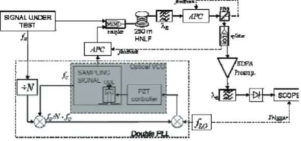
The working principle of the quasi-asynchronous optical sampling oscilloscope is shown in Fig.1. The optical sampler exploits a nonlinear interaction between the signal under test and the sampling signal: the sampling signal is an ultra-short pulse train at low repetition rate acting as a pump. The two optical signals are coupled together and launched into a High Nonlinear Fiber (HNLF), exploiting the ultra-fast response time (<50fs) of the Kerr effect.
Fig. 1. Schematic of the quasi-asynchronous sampling
oscilloscope.
Every sampling pulse induces Cross Phase Modulation (XPM) on the signal under test, and the induced phase shift turns directly in a polarization rotation. Using an Automatic Polarization Controller (APC) and a polarizer at the output, through a reset operation it is possible to isolate the rotated portion of the signal. An optical BPF (Band-Pass Filter) centred at the signal wavelength is used in order to minimise the out-of-band noise and remove the pump. The efficiency of polarization rotation can be maximized imposing a difference of 45° in the polarization state of the two signals, through another APC at the output of the sampling source. Each APC includes an electro-optical feedback, making the scheme polarization insensitive. Using a local oscillator and a double PLL scheme, a fixed frequency mismatch is imposed and maintained between the repetition rates of the two signals as shown in Fig. 1. The frequency mismatch leads to a shift of the sampling signal on the signal under test. If the signal under test is periodic with T=NTb (being Tb the bit time) and
N the sequence bit number, the period of the sampling signal can be chosen as TC = NTb + ∆t, where ∆t is the desired temporal resolution. In this way samples are collected consecutively, so no post processing is required, as shown in Fig. 2. Due to the low repetition rate, it is possible to reconstruct the sampled signal using a slow PD (PhotoDiode) and a low-bandwidth oscilloscope. Through the electrical PLL scheme, the difference between the Nth sub-multiple of the signal frequency fS and the multiple of the sampling frequency (fLO=fS/N-fC) is maintained constant. Signal under test Sampling Signal t t TS TC t0 t1 ……… ti Signal under test Sampling Signal t t TS TC t0 t1 ……… ti t0 t1 ……… ti
Fig. 2. Working principle of the quasi-asynchronous
sampling operation.
Correctly driving the piezoelectric delay line inside the optical sampling source cavity, the source acts as an Optical VCO (OVCO). The frequency mismatch is imposed using a local oscillator and is determined by the desired resolution, according to the formula:
2 2 2 S S LO tN f f t N f N S t f ≅∆ ⋅ ⋅ ∆ + ⋅ ∆ = N>>∆t⋅fS
If N=128, it is possible to resolve every bit pattern with a period of 2n bit and n ≤ 7. When fS = 10GHz, it is possible to obtain a 100 fs temporal resolution choosing a repetition rate fC = 78.124MHz for the sampling signal and a frequency mismatch fLO ~ 3KHz. This solution provide a refresh time of ~ 1.6 ms. Moreover, tuning the repetition rate of the sampling signal, it is possible to resolve also bit pattern with a standard length of 2n-1 bit.
III. EXPERIMENTAL RESULTS
In the experimental measurements N=8 have been used. The signal to be sampled is obtained through a 10GHz Actively Mode-Locked Fiber Laser (AMLFL) producing 4-ps (measured with a commercial autocorrelator) pulses. The pulse train is modulated by a Mach Zehnder modulator using a 8 bit pattern. The sampling signal is obtained with a second AMLFL acting as an optical VCO, followed by a compression stage to reach a pulsewidth of 600 fs. A ∆t of 500 fs is imposed setting a frequency mismatch fLO=781.25 KHz. The sampling pulses are then
Analisi e realizzazione di un campionatore ottico quasi-asincrono basato su cross-phase modulation per segnali ultra-veloci
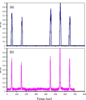
coupled with the signal under test into the HNLF. The mean power of the sampling signal is set around 6dBm, while the signal power is maintained low (<0dBm) to avoid Self Phase Modulation. 0 0,1 0,2 0,3 0,4 0,5 0,6 0,7 0,8 0,9 1 a. u . (a) Time [ps] 0 0,1 0,2 0,3 0,4 0,5 0,6 0,7 0,8 0,9 1 0 100 200 300 400 500 600 700 800 (b) a.u. a. u .
Fig. 3. Comparison between acquired curve through a commercial 53 GHz oscilloscope (a) and the proposed QA
optical sampler (b).
The wavelengths of the two signals have been set at 20nm distance; this doesn’t affect XPM and reduces the spectral crosstalk. After the polarizer, the optical samples are then amplified, filtered, photo-detected and viewed on a 600 MHz real-time oscilloscope. Fig. 3 reports a comparison between the bit sequence evaluated on a 53GHz commercial oscilloscope (a) and the one reconstructed by means of the proposed scheme (b). Due to the bandwidth limitations, the 53GHz oscilloscope is not able to measure the real pulsewidth; on the other hand, the optical sampling oscilloscope presents an higher resolution. In order to confirm the effectiveness and the accuracy of the proposed sampler, we compared the obtained sampled trace with the one supplied by a commercial autocorrelator. The inset in Fig. 4 shows the optical sampled pulse shape, whose measured pulsewidth is 4.2 ps and Fig. 4 reports a very good agreement between the autocorrelation supplied by the commercial autocorrelator and the one evaluated from the sampled pulse. 0 0,1 0,2 0,3 0,4 0,5 0,6 0,7 0,8 0,9 1 0 10 20 30 40 5 time (ps) a. u . 0 commercial autocorrelator optical sampler 0 0,1 0,2 0,3 0,4 0,5 0,6 0,7 0,8 0,9 1 0 2 4 6 8101214 161820 time (ps) a. u . 0 0,1 0,2 0,3 0,4 0,5 0,6 0,7 0,8 0,9 1 0 10 20 30 40 5 time (ps) a. u . 0 commercial autocorrelator optical sampler 0 0,1 0,2 0,3 0,4 0,5 0,6 0,7 0,8 0,9 1 0 2 4 6 8101214 161820 time (ps) a. u .
Fig. 4. Pulse autocorrelation obtained from a commercial
autocorrelator and the QA optical sampler. The inset
shows the acquired pulse trace.
IV. CONCLUSIONS
We have proposed an implementation of a QA all-optical sampling oscilloscope based on XPM-induced polarization rotation in fibre, able to benefit from the advantages of both synchronous and asynchronous methods. In particular, this kind of oscilloscope is able to resolve long bit sequences (tens of nanoseconds) with sub-ps-resolution and low refresh time (<1.6ms). The optical sampling of a 8 bit sequence at 10 Gbit/s of a 4-ps signal has been experimentally demonstrated, showing a very good accuracy as confirmed by comparisons with commercial instruments.
REFERENCES
[1] R. Trebino et al., “Measuring ultrashort laser pulses in the time-frequency domain using frequency-resolved optical gating”, Rev. Sci. Instrum., vol. 68, no. 9, pp 3277-3295, 1997.
[2] B. C. Thomsen et al., “Ultra-sensitive all-optical sampling at 1.5 µm using waveguide two-photon absorption”,
Electron. Lett., vol. 35, no. 17, pp. 1483-1484, Aug. 1999.
[3] R. L. Jungerman et al., “1-THz bandwidth C- and L-band optical sampling with a bit rate agile timebase”, IEEE
Photon. Technol. Lett., vol. 14, no. 8, pp. 1148-1150,
Aug. 2002.
[4] J. Li et al., “0.5-Tb/s Eye-Diagram Measurement by Optical Sampling Using XPM-Induced Wavelength Shifting in Highly Nonlinear Fiber”, IEEE Photon.
Technol. Lett., vol. 16, no. 2, pp. 566-568, Feb. 2004.
[5] A. Bogoni et al., “Asynchronous optical sampler for monitoring of 40 Gbit/s signals in C-band”, in Proc.
COIN-NGNCON, WeB3-6, 2006.
[6] G. Meloni et al., “Real-time ps-resolution optical sampler based on XPM-induced polarization rotation in 1-meter-long bismuth oxide fibre”, in Proc. ECOC’05, vol. 1, pp. 63-64, Sept. 2005.
[7] P. A. Andrekson, “Picosecond optical sampling using four-wave mixing in fibre”, Electron. Lett., vol. 27, no. 16, pp. 1440-1441, Aug. 1991.
[8] E. Benkler et al., “Frequency-Offset PLL for Synchronous Optical Sampling of OTDM Signals” , IEEE
Photon. Technol. Lett., v.19, n.5, pp. 266-269, March
2007.
[9] S. Kawanishi et al., “High sensitivity waveform measurement with optical sampling using quasi-phasematched mixing in LiNbO3 waveguide”, Electron.
Lett., vol. 37, no. 13, pp. 842-843, June 2001.
[10] M. Shirane et al., “A compact optical sampling measurement system using mode-locked laser-diode modules”, IEEE Photon. Technol. Lett., vol. 12, no. 11, pp. 1537-1539, Nov. 2000.