1
UNIVERSITÀ DI PISA
Dipartimento di Oncologia, dei Trapianti e delle Nuove Tecnologie in Medicina
Corso di Dottorato in Tecnologie per la Salute:
Valutazione e Gestione delle Innovazioni nel Settore Biomedicale XXII Ciclo
SSD:ING/IND/34
Ph.D Thesis
METHODOLOGY FOR RESEARCH AND DEVELOPMENT OF NOVEL MEDICAL DEVICES FOR MINIMALLY INVASIVE INTERVENTIONS
Elena Troia
2 UNIVERSITÀ DI PISA
Dipartimento di Oncologia, dei Trapianti e delle Nuove Tecnologie in Medicina
Corso di Dottorato in Tecnologie per la Salute:
Valutazione e Gestione delle Innovazioni nel Settore Biomedicale XXII Ciclo
Ph.D Thesis
METHODOLOGY FOR RESEARCH AND DEVELOPMENT OF NOVEL MEDICAL DEVICES FOR MINIMALLY INVASIVE INTERVENTIONS
Elena Troia
Submitted to the University of Pisa in partial fulfilment of the requirements for the degree of Doctor of Philosophy
Tutor:
Prof. Andrea Pietrabissa:
Dr. Bernardo Magnani
Prof. Arianna Menciassi
Prof. Paolo Dario
It was defended on February 2011
3
1 Abstract
The design of innovative medical device requires extensive and hard efforts to reach good results in terms of safety, efficacy and cost effectiveness. First of all the idea has to be set and a wide search of state of the art, both technological and academic, has to be developed. Then the materials, manufacturing processes and design constraints have to be understood. In this work three examples of innovative surgical devices for minimally invasive surgery and assistance have been presented.
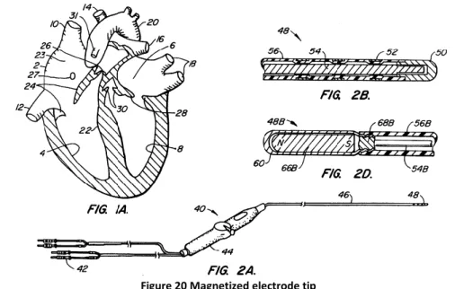
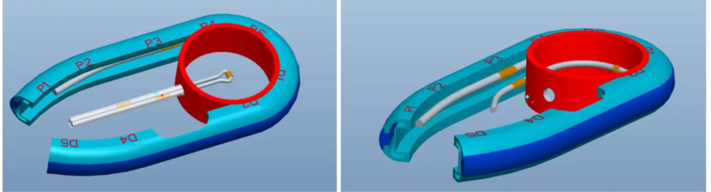
The Muneretto Beam catheter is a new device for atrial defibrillation. Starting from a catheter produced by Estech1 company for the treatment of atrial fibrillation by ablating cardiac tissue during surgery, a system for the magnetic guidance of the same has been implemented. Thanks to finite element analysis of various configurations of magnets and to several in vitro tests, a final configuration which allows a good balance between the sliding of the catheter on the tissues and the magnetic interaction and adhesion to tissues has been found. Further attention has been taken to the development of the cover and the right configuration and method of use of the device.
The VideoDrain system is a new catheter for the monitoring of post-operative wound. After critical surgical procedures it is necessary to monitor the status of the surgical wound for avoiding second look surgical interventions. Therefore a new balloon catheter for allowing the vision of the abdominal cavity has been produced. Several in vitro and in vivo trials have been conducted and the device is at the pre-industrial stage.
The FloSeal GI cath. is a new device for the gastrointestinal release of an haemostatic substance of the Baxter2 company: the Floseal thrombin matrix. It consists in a balloon catheter suited for the use in the lower and upper gastrointestinal tract in the occurrence of bleedings during endoscopic procedures. This device has been CE labelled and is now on the market.
All the devices described in this work come from ideas of surgeons leader in innovation in the field of minimally invasive interventions. Their collaboration has been fundamental for the several phases of design and tests of the devices.
This Ph.D. thesis is divided into five chapters. In the Introduction chapter the process of research and development of innovative MDs for minimally invasive surgery has been illustrated. The second chapter shows the efforts done to find a working configuration for the Muneretto Beam catheter and the subsequent first prototypes developed. The progress in the design of VideoDrain has been explained in the third chapter; the whole process goes from the idea to the animal test on prototypes and a preliminary risk analysis. The development of the Floseal GI Catheter is depicted in the fourth chapter; all the details of the materials used and tests done to ensure a CE mark have been reported. Finally, in the Conclusion chapter I have reported some lessons learned from the work in the field of MDs, as a student, researcher and engineer at close contact with the world of surgery and minimally invasive technologies. Some papers about a preliminary research activity in the field of minimally invasive surgery and robotic interventions have been also enclosed. These works have been very useful to start the understanding of the complex and amazing world of MIS.
1 http://www.estech.com/
2
4 Alla mia cara famiglia
5 Acknowledgements
Vorrei esprimere gratitudine innanzitutto per lo staff del laboratorio Endocas e dell’Università di Pisa, per i Professori Mosca e Pietrabissa, che mi hanno offerto l’opportunità di svolgere un dottorato presso la facoltà di Medicina e Chirurgia.
Ringrazio tutti i chirurghi che nel tempo mi hanno guidato nel mondo della medicina: Il dott. Morelli, il Prof. Muneretto, Il dott. Peri, Il dott. Basili, il dott. Spera e il prof. Scozzarro.
Uno speciale omaggio va al laboratorio Crim della Scuola Superiore Sant’Anna con tutto il personale accademico e tecnico ,al Prof. Dario e alla Prof. Menciassi,all’ing. Funaro, Gabriele, Carlo che per anni hanno supportato il mio lavoro di ricerca e comprensione della realtà ingegneristica.
Esprimo riconoscenza l’Ing. Magnani per avermi consentito l’ingresso nel mondo dei dispositivi medici e l’ing. Valori per la amichevole collaborazione quotidiana.
Grazie a tutti gli amici pisani e non, che mi hanno accolto in terra toscana , facendomi sentire sempre a casa (Cinzia, Marina, Claudia, Cristina, Benny, Lele, Marco, Nicola, Filippo, Gioel, Silviona, il Conte, Michela, Cristina, i musicanti)e gli amici lontani ma sempre nel mio cuore (Angela ,Valentina, Elfra, Chiara, Angela, Dona, Giulia).
Ringrazio la mia famiglia che da sempre crede in me, mi aiuta e sostiene in tutte le scelte e difficoltà. Grazie ai miei fratelli, la mia forza, a nonni e zii, la mia pazienza e ai miei genitori, la mia energia e costanza.
Ringrazio Pia, Alessia e Gabriele per la loro allegria e Loris per tutto l’amore che ogni giorno mi regala e per tutto quello che ci regaleremo.
6
2 Table of contents
1 Abstract _______________________________________________________________ 3 Acknowledgements _______________________________________________________________ 5 2 Table of contents ________________________________________________________ 6 3 Research and Development of medical devices _______________________________ 10 3.1 Design for Minimally Invasive Surgery _________________________________________ 10 3.2 Methodologies for design and development of innovative devices _________________ 12 3.3 Design of medical components ______________________________________________ 15 3.3.1 Microtubes _____________________________________________________________________ 15 3.3.2 Materials _______________________________________________________________________ 16 3.3.3 Design for manufacturability _______________________________________________________ 19 3.3.4 Assembly Techniques _____________________________________________________________ 22 3.3.5 Component Outsourcing __________________________________________________________ 22 3.3.6 Sterilization Methods _____________________________________________________________ 23 3.4 Regulation _______________________________________________________________ 23
3.4.1 Certification aspects: definitions and classification _____________________________________ 24 3.5 Quality system ___________________________________________________________ 26 3.6 Risk Management _________________________________________________________ 27 3.6.1 The methodology of ISO 14971 _____________________________________________________ 29 4 Muneretto Beam Navigation device ________________________________________ 30 4.1 Analysis of the medical background __________________________________________ 30
4.1.1 Clinical evaluation in patients with AF ________________________________________________ 31 4.2 Surgical treatments for atrial fibrillation _______________________________________ 31
4.2.1 The Maze Procedure _____________________________________________________________ 31 4.2.2 Circumferential pulmonary vein ablation (CPVA) _______________________________________ 32 4.2.3 Radiofrequency ablation endoscopic procedures _______________________________________ 33 4.2.4 Left atrial appendage (LAA) excision _________________________________________________ 34 4.2.5 Robotically Assisted AF surgery _____________________________________________________ 34 4.3 Technological state of the art ________________________________________________ 35
4.3.1 Magnetically guided systems _______________________________________________________ 35 4.3.2 Robots for atrial fibrillation ________________________________________________________ 36 4.4 Analysis and search of materials _____________________________________________ 37
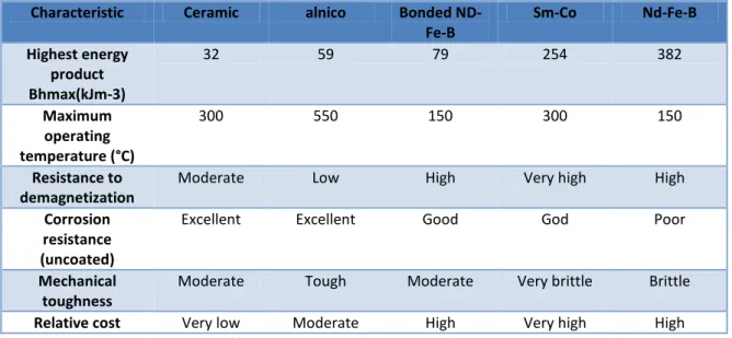
4.4.1 Permanent magnets ______________________________________________________________ 37 4.4.2 The B-H Curve ___________________________________________________________________ 39 4.5 Design History ____________________________________________________________ 39
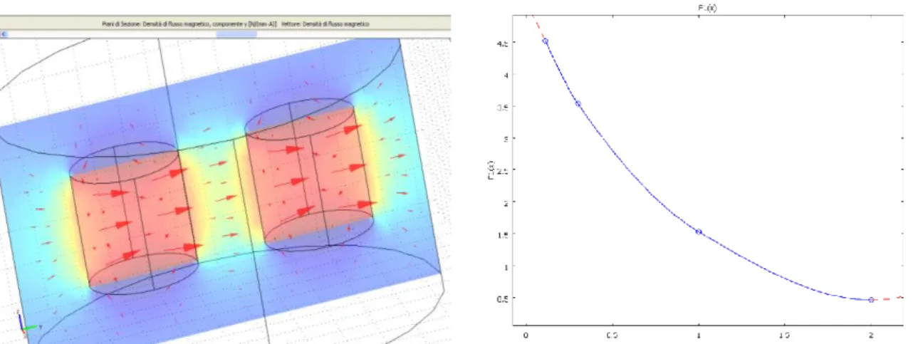
4.5.1 Muneretto approach _____________________________________________________________ 40 4.5.2 Analysis of potential configurations _________________________________________________ 41 4.5.3 Finite Element Analysis ___________________________________________________________ 44 4.5.4 Model validation ________________________________________________________________ 48 4.5.5 Main FEA results _________________________________________________________________ 49 4.6 Prototypes and Tests ______________________________________________________ 52 5 Video drain ____________________________________________________________ 55
5.1 Analysis of the medical background: Anatomy and Complications of abdominal surgical wounds ________________________________________________________________________ 55
7 5.1.2 Ethiology and Pathophysiology _____________________________________________________ 56 5.2 Market Analysis __________________________________________________________ 58 5.3 State of the art: Commercial systems _________________________________________ 58 5.3.1 Abdominal drainage tubes _________________________________________________________ 59 5.3.2 Endoscopic covers _______________________________________________________________ 60 5.3.3 Trocar for extraperitoneal dissection (Balloon dissectors) ________________________________ 60 5.3.4 Balloon systems for diagnosis and intervention without insufflation _______________________ 60 5.3.5 Abdominal ultrasound ____________________________________________________________ 61 5.3.6 Diagnostic Laparotomy ___________________________________________________________ 61 5.3.7 Abdominal radiography and computer tomography scan ________________________________ 62 5.3.8 Analisys of competitors features ____________________________________________________ 62 5.4 Patent Search ____________________________________________________________ 64 5.5 Design of the device _______________________________________________________ 66 5.5.1 Analysis of potential configuration and Computer assisted design _________________________ 67 5.5.2 Analysis of materials _____________________________________________________________ 69 5.5.3 Final configuration and prototype ___________________________________________________ 73 5.5.4 Accessories _____________________________________________________________________ 75 5.6 Tests ___________________________________________________________________ 76
5.6.1 Mechanical tests _________________________________________________________________ 76 5.6.2 Animal trials ____________________________________________________________________ 78 5.7 Risk Managment __________________________________________________________ 82
5.7.1 VideoDrain intended use __________________________________________________________ 82 5.7.2 Classification ____________________________________________________________________ 82 5.7.3 Functional Analysis _______________________________________________________________ 83 6 Floseal GI (Gastro Intestinal) catheter ______________________________________ 86 6.1 Analysis of the medical background: bleedings in upper and lower gastrointestinal tract 86
6.1.1 GI Endoscopy ___________________________________________________________________ 86 6.1.2 Ethiology and Pathophysiology _____________________________________________________ 86 6.2 Market Analysis __________________________________________________________ 88 6.3 State of the art: Commercial systems and therapies _____________________________ 89 6.3.1 Endoscopic injection needles _______________________________________________________ 89 6.3.2 Thermo coagulation ______________________________________________________________ 90 6.3.3 Mechanical Devices ______________________________________________________________ 91 6.3.4 Combined Therapy _______________________________________________________________ 92 6.3.5 Hemostyptic sprays ______________________________________________________________ 92 6.3.6 Analysis of competitors features ____________________________________________________ 92 6.4 Intellectual property _______________________________________________________ 94
6.4.1 Accessory device: Floseal Matrix ____________________________________________________ 95 6.5 Design History ____________________________________________________________ 96
6.5.1 Initial Specification _______________________________________________________________ 96 6.5.2 Underlined problems _____________________________________________________________ 97 6.5.3 Connections ___________________________________________________________________ 105 6.5.4 Analysis of materials ____________________________________________________________ 105 6.5.5 Final configuration and prototype __________________________________________________ 109 6.5.6 Manufacturing process __________________________________________________________ 110 6.6 Test sessions ____________________________________________________________ 114
6.6.1 In vitro tests ___________________________________________________________________ 114 6.6.2 Ex-vivo tests ___________________________________________________________________ 115 6.6.3 Control tests ___________________________________________________________________ 117
8
6.7 Risk Management ________________________________________________________ 118 6.7.1 Risk assessment ________________________________________________________________ 118 6.7.2 Risk evaluation and control _______________________________________________________ 123 6.7.3 Sterilisation method _____________________________________________________________ 124 6.7.4 Instruction for Use – IFU _________________________________________________________ 125 6.7.5 Packaging _____________________________________________________________________ 127 7 Conclusions ___________________________________________________________ 129 8 List of publications _____________________________________________________ 131 9 Bibliography __________________________________________________________ 132 10 Annex I ______________________________________________________________ 137 Classification of Medical devices ___________________________________________________ 137 11 Annex II ______________________________________________________________ 140
Biocompatible materials properties ________________________________________________ 140 12 Annex III _____________________________________________________________ 142
Flow Chart – Risk Management Activities in Design and Development ____________________ 142 Grids for Risk and Measures Assessment ____________________________________________ 142 Risk Assessment Criteria _________________________________________________________________ 142 Measures Assessment Criteria ____________________________________________________________ 143 13 Annex IV _____________________________________________________________ 144 14 Annex V ______________________________________________________________ 145 Results of FE model validation ____________________________________________________ 145 Comparison with datasheets ______________________________________________________ 145 (magn_perm) d22_d22 axially ____________________________________________________________ 145 (magn_perm) d24_d24 axially ____________________________________________________________ 146 (t.l.v.) d24_d24 diametrically _____________________________________________________________ 146 Comparison with tests __________________________________________________________________ 146 Validation tests with hkcm magnets ________________________________________________ 148
Magnet-Cylinder Z02x02ND-48H with iron plate _____________________________________________ 148 15 Annex VI _____________________________________________________________ 149 Tests results-September 2010 _____________________________________________________ 149 Configuration 1 ________________________________________________________________________ 149 Configuration 2 ________________________________________________________________________ 149 Configuration 3 ________________________________________________________________________ 149 Configuration 4 ________________________________________________________________________ 150 Configuration 5 ________________________________________________________________________ 150 Configuration 6 ________________________________________________________________________ 150 October 2010 __________________________________________________________________ 150 Configuration 1 ________________________________________________________________________ 150 Configuration2 ________________________________________________________________________ 151 Configuration3 ________________________________________________________________________ 151 Configuration 4 ________________________________________________________________________ 151 Configuration 5 ________________________________________________________________________ 152 Configuration 6 ________________________________________________________________________ 152 16 Annex VII _____________________________________________________________ 153
9
Drawings VideoDrain ____________________________________________________________ 153 17 Annex VIII ____________________________________________________________ 156
FloSeal GI cath. prototypes _______________________________________________________ 156 18 Annex IX _____________________________________________________________ 158
Floseal GI cath tests _____________________________________________________________ 158 19 Annex X ______________________________________________________________ 166
10
3 Research and Development of medical devices
3.1 Design for Minimally Invasive Surgery
The medical practice is constantly being qualified through technological advances brought about by new Medical device (MD). Bringing a MD to the marketplace can be a long and hard road. In this Ph.D. thesis, a strategy to develop innovative MDs for various applications in minimally invasive surgery will be analyzed and implemented in few case studies.
Figure 1 Minimally invasive surgery (MIS) procedures
Using laparoscopic techniques, specialized equipment and at times robotic assistance, the expert surgeons are able to make tiny, precise movements through very small incisions. These innovative techniques cause minimal trauma to the body. Minimally invasive surgery can offer the following advantages to the patients:
Smaller incision, which reduces pain and shortens recovery time, as well as resulting in less post-operative scarring
Reduced hemorrhaging, which reduces the chance of needing a blood transfusion.
Less pain, leading to less pain medication needed
Although procedure times are usually slightly longer, hospital stay is less, and often with a same day discharge which leads to a faster return to everyday living
Reduced exposure of internal organs to possible external contaminants thereby reduced risk of acquiring infections.
The various step (see Figure 2) through a valid development of MD starts from the specification of an idea, born from a real need of improvement of patients’ quality of life. Anatomical and physiological knowledge and a full medical literature research are necessary to implement that idea. Many of these devices are invented by the physicians who foresaw the potential benefits the new device would have on their own practice and that of their colleagues. After a specific market analysis and a feasibility study a first prototype is made in order to assure some initial critical aspects. Thanks to the close cooperation with surgeons and observation of clinical practice, a phase of co-invention starts. Engineers and surgeons cope to find a common language and define strict specification for a prototype which become a “proof of concept”. Around this tangible idea active business and feasibility plans are compiled. The device must respect some fundamental issues in order to be acceptable for production. First of all the marketability and effectiveness. They must assure a reduced
11 recovery and hospitalization time. With the use of the new device the abilities of the surgeon should be increased and the procedures simplified. Ergonomics and usability must be pursued in the design.
Figure 2 The rules of safe and effective Innovation
Protecting and licensing commercial rights for a new MD could mean the difference between success or failure. A patent protects against the unauthorized use of an idea and the inventor of a MD should take advantage of the available intellectual property rights to protect and defend against the unlawful infringement or theft of valuable intellectual property associated with a new MD.
In conjunction with protecting the idea, it is necessary to develop a strategic business plan. It has several purposes. First, it will help to identify a "roadmap" for how the MD can be successfully marketed and define benchmark objectives and realistic dates to achieve those goals. Second, the strategic business plan is imperative if the company will need to raise equity or borrow money to fund the business venture.
The cost and the safety are key issues for a MD. The material, the technologies and the processes used must be compliant with regulations. The device must be approved, certified and classified with existing legislation depending from the country of deployment of the device.
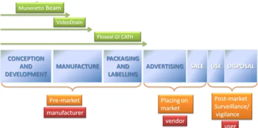
The life of a MD can be divided in seven phases (1) from conception and development to disposal. The systems and devices described in this PhD work are enclosed in the first pre-market phase through various level of examination (Figure 3).
12
Figure 3 Medical Device life span and subjects involved in each phase
3.2 Methodologies for design and development of innovative devices
TRIZ is a method and a set of tools developed in Russia in 1946; starting from the examination of a very large number of patents, it deducts the general laws underlying the evolution of technical systems and propose a system to develop innovative solutions. The search of solutions is methodical and is obtained overcoming the technical and physical contradiction which comes with the search of improvement. In Figure 4 3it is represented the process of development of new innovative products. All the main activities (violet) are surrounded by sub-activities (green) which contribute to clarify and analyze the work in a systematic way.
3
JOC- Job Outcomes and Constraints CAM-Computer Aided Manufacturing CAE- Computer Aided Engineering CIM-Computer Integrated Manufacturing FEM-Finite Element method
MRP-Material Requirements Planning MKTG-Marketing
13
Figure 4 Development of new products
The design process followed in this work represents an implementation of the above scheme and it can be summarized in the following phases:
Clear Identification of the intended use
Analysis of the medical background
Market analysis
State of the art and patent search
Analysis of potential configurations and associated CAD4
Analysis and search of materials, components
Realization of Prototypes
Preliminary tests and FEM
Choice of final configuration
Deployment of the device
Mechanical strength tests
In vivo tests
Study and editing of technical file and Instruction of Use
CE mark, labelling, packaging
Post market surveillance.
Some characteristics (2) in healthcare device design can be identified and Each of them is briefly described below:
4
14
Functionalism refers to the belief that the intended function of something should determine its design, construction, and choice of materials. It is also seen as a philosophy which emphasizes on practical and utilitarian concerns
Ergonomics is the scientific discipline concerned with the understanding of interactions among humans and other elements of a system, and the profession that applies theory, principles, data, and methods to design in order to optimize human well-being and overall system performance. In medical design, the domain of ergonomics mainly refers to physical ergonomics, which deals with the human body's responses to physical and physiological loads
Technology can refer to the development and application of techniques for manufacturing and productive processes; a method of applying technical knowledge, and a sum of practical knowledge with regards to material culture
Appearance and Aesthetics refers to product qualities such as smoothness, shininess/reflectivity, texture, pattern, curviness, color, simplicity, usability, velocity, symmetry, naturalness, and modernism
Universal Design is related to "inclusive design" and "design for all," is an approach to the design of products, services and environments to be usable by as many people as possible regardless of age, ability or situation
User experience and Emotional Design is about improving people psychologically to feel that they are recuperating better overtime.
During the design phase the principles of Human Factor Engineering has been followed; its application to system design improves ease of use, system performance and reliability, and user satisfaction, while reducing operational errors, operator stress, training requirements, user fatigue, and product liability. In Medical device design it is very important not to forget that the beneficiary of the invention and its user are the patient and the medical professional, so all the efforts of the designer must be focused on these subjects’ needs.
Addressing use-related hazards should be undertaken within the context of a thorough understanding of how a device will be used. Essential components of this understanding include:
Device users, (e.g., patient, family member, physician, nurse, professional caregiver)
Typical and atypical device use
Device characteristics
Characteristics of the environments in which the device will be used
The interaction between users, devices, and use environments.
Following a thorough understanding of device use, specific ways that devices could be used, that are likely to result in hazards, should be identified and investigated through analysis and testing. In addition to investigating known or suspected problems with device use, testing prototype devices with users can identify ways of using devices that could be hazard-related, that were not anticipated. This is important because it is extremely difficult to identify all significant device use problems in advance.
After use-related hazards are understood, the hazards are mitigated or controlled by modifying the device user interface (e.g., control or display characteristics, logic of operation,
15 labelling) or the abilities of users to use the device (e.g., training, limiting use to qualified users).
3.3 Design of medical components 3.3.1 Microtubes
The main sub components used for minimally invasive devices are catheters, available in different configurations and materials. Catheters are medical devices, typically in the form of a tube, that are inserted into the body to remove fluid, create an opening, or deliver a drug. All the device described in the current work rate catheters of different shapes and dimensions between their main components.
Among the main design qualities of tubings (3), the profile or form factor as well as its trackability, pushability, and torqueability can be mentioned. Trackability means the ability of a catheter to go through tortuous paths to its ultimate destination. It depends on:
Shaft flexibility
Friction between a catheter and its surrounding environment
Column strength, which is the capacity of the tube to withstand axial forces without compression or stretch.
Catheter torqueability describes the behaviour of a tube when a moment of torque is placed about its longitudinal axis (Figure 5).
Figure 5 Torque or moment (M) applied to a tube.
For small deflections, the tube's mechanical properties approximate a spring system, in which torsional stiffness is determined such that:
where is the torsional spring constant, G is the shear modulus, J is the polar moment of inertia, and L is the length of the catheter shaft.
Tube flexibility can be modelled as a clamped beam system subject to a downward force at the beam, as shown in Figure 6.
16
Figure 6 Flexibility (F) or bending force applied to end of tube
For small deflections, the tubing approximates a spring system, with the flexural stiffness determined by:
where is the flexural spring constant, E is the modulus of elasticity, I is the moment of inertia, and L is the length of the catheter shaft. In many cases, it is desirable to minimize the flexural stiffness of the catheter (6.5.2) and it’s possible by :
Minimizing the moment of inertia
Minimizing the modulus of elasticity by using a soft material
Increasing the overall part length.
The pushability is the response of a tube when a longitudinal force is applied along its axis (Figure 7).
Figure 7 Force applied on the longitudinal axis of a tube
For small deflections, the tubing properties can be considered to approximate a spring system, in which the longitudinal stiffness of the spring is determined by the equation:
Where is the longitudinal spring constant, E is the modulus of elasticity, A is the cross-sectional area, and L is the length of the catheter shaft. In order to maximize pushability, it’s necessary to maximize the parameter :
•By maximizing the cross-sectional area of the tubing
•By maximizing the modulus of elasticity using a stiffer material •By decreasing the overall part length.
In minimally invasive surgery, often it is very important not to augment the diameter of the tubing, so there is a wide search of new materials which offer a good compromise between stiffness, flexibility and biocompatibility.
Commonly, composite tubing designs are used for catheter delivery systems. These include designs consisting of one or more plastic materials (6.5.4) as well as wire-reinforced (braid or coil) designs (VideoDrain device 5.5.1).
3.3.2 Materials
In designing a medical tube, it is important considering four basic physical properties of materials, which are critical to function (in Table 49 some properties of the most common materials for medical use):
17
durometer (the hardness of the resin)
flex modulus (the flexibility of the resin)
ultimate tensile (the force it takes to break the tube)
elongation (how much the material will stretch before breaking).
Two other important criteria are biocompatibility of the resin and postextrusion processability. The biocompatibility of catheters, as with other medical devices, can be defined as the ability of the device to perform its intended function without eliciting undesirable side effects. Their biocompatibility is related not only to the basic polymers, but also to the various additives used.
It is also important to understand if the materials, once processed, can be used without hazards. Infact accidental release of particles of materials can occure for several purposes: friction, temperature, wrong conditions of use, intrinsic features of the material.
Polyvinylchloride (PVC)(4) is an inexpensive plastic material that is used in a wide variety of industrial and domestic applications. PVC is used in some situations with minimal additives, in which case it is a hard rigid material; most often, an additive described as a plasticizer is used, and the resulting plasticized, or soft, PVC finds extensive applications, especially in medical tubings. Many short-term catheters and drains are used in the clinic, including umbilical vessel catheters, wound drainage tubes and osteotomy shunts.
Natural rubber latex (NRL) is a highly elastic, very-low-durometer material exhibiting high tear resistance and high elongation. It has long (5) been used to manufacture a wide range of healthcare products and components for medical devices. But as latex allergy has become a major occupational health problem for healthcare workers, non-allergenic alternatives to NRL are in greater demand to meet the needs of the medical device industry for latex-free materials.
Silicones, one of the most thoroughly tested and widely-used groups of biomaterials, are well known for their intrinsic biocompatibility and biodurability. These key characteristics have been attributed to the material’s inherent chemical and thermal stability, low surface tension and hydrophobicity. As a result of these properties, silicones have the benefit of extensive application in catheters and other medical products. Silicones have been successfully applied in short- and long-dwelling catheters, drains, and shunts for over sixty years (6). Silicone elastomer is a thermosetting material, capable of being processed by various moulding, dipping, and extrusion methods. Like polyurethanes, silicones are excellent for low-durometer applications—strong, resilient, stretchable, and more stable than latex.
Silicone elastomers used in medical device applications normally include reinforcing filler; Incorporation of reinforcing filler into the cross-linked matrix reduces material stickiness, increases hardness, and enhances mechanical strength. Silicone catheter raw materials are more expensive than legacy materials such as latex and PVC, but when examining healthcare choices, possibility of infection should be taken into account.
TPU is a thermoplastic Polyurethane (see VideoDrain materials) and has gained wide acceptance as an alternative to silicone. When employed as part of an invasive device, polyurethanes soften considerably within minutes of insertion in the body, reducing patient discomfort and the risk of vascular trauma. The high strength and ease of processing of polyurethanes make them an excellent choice for soft-elastomer applications. Advances in PU
18 formulations have made polyurethane a suitable replacement for latex in a variety of medical device applications.
A prominent device application (5) for polyurethane and silicone is in low-pressure elastomeric balloons, as the ones used in the current work. These components are different from high-pressure medical balloons, which are made of non- or low-compliant materials such as PET and nylon and are generally used to apply force in a variety of diagnostic and therapeutic procedures, including angioplasty and other dilatation applications.
Fluoropolymers (7) exhibit very good lubricity compared with other plastics. PTFE is the most lubricious polymer available, with a coefficient of friction (COF) of 0.1, followed by fluorinated ethylene propylene (FEP), with 0.2. These two polymers represent the vast majority of all fluoropolymer tubing used in medical devices. Fluoropolymers, especially PTFE, has an excellent biocompatibility
PTFE (Teflon) is very difficult to extrude, due to its high viscosity and it needs particular material for the equipment because of its high corrosion in the molten state.
3.3.2.1 Disposal
For several years, regulations (8) for the reduction of waste and minimization or elimination of hazardous substances have been enforced in the European Union (EU). Standards such as the Waste Electrical and Electronic Equipment (WEEE); Restriction on Hazardous Substances (RoHS); Registration, Evaluation, and Authorization of Chemicals (REACH); and the Energy Using Products (EuP) regulations have significantly altered the manufacturing processes of electronics at industrial and consumer products companies.
The WEEE Directive requires the use of specific labelling, compliance with disposal restrictions, and creation of instructions for end-of-life management and recycling.
Methods such as Six Sigma and lean manufacturing promote low defect manufacturing and encourage process flexibility. Lean manufacturing specifically targets and attempts to reduce seven waste streams, namely overproduction, waiting time, transportation, processing, inventory, motion, and scrap. These concepts, while originally developed to improve efficiency and reduce production costs, also align with many of the goals of sustainable design and production.
Disposal of medical products made from PVC can be problematic. The preferred biohazard waste disposal method for hospitals is often incineration. Incineration of used PVC medical devices such as catheters and tubing generates hazardous gases including hydrochloric acid (HCl), dioxins, and polychlorinated biphenyls (PCBs). In addition to the environmental impact of such air population, the HCl shortens the life of the incinerator.
With respect to disposable medical products, choosing materials that limit environmental damage during disposal and incineration can reduce toxic air emissions and reduce waste processing costs. In addition, products that have a durable or reusable component and smaller disposable components can minimize waste without damaging the lucrative nature of the disposable device business model. The critical factor in the durable or disposable product concept is to create a simple, repeatable interface between the two component sections so as not to impair the functionality or efficacy of the product.
19
3.3.3 Design for manufacturability
Achieving an efficient catheter system figures among the fundamental design requirements in developing a novel medical procedure.
Most specifications for medical tubing consist of a drawing of a tube with the material, dimensions and tolerances. For single lumen tubing(9), the dimensions will usually include two of the following three dimensions; inner diameter (ID), outer diameter (OD) and the tubing wall thickness, along with their associated tolerances. In addition, the tubing length and tolerance would be included unless the tubing is to be provided in a continuous length on a spool.
One of the pressing issues for any new product(3) or process development project is the complexity of the required manufacturing process and its expected yields. Optimizing the manufacturability of the design from the beginning of the development process is a key issue for medical devices in particular. Oftentimes, the process parameters and the equipment used to extrude the tubing are as important or even more important than the actual dimensions of the tube. The tolerance requirements for metal instruments are completely different from those for plastic molded components. The device must be properly designed in order to have proper function in spite of these variations.
The following sections summarize recent trends in catheter manufacturing, including assembly techniques, component outsourcing tactics, and sterilization methods. The most important manufacturing techniques for the industry of plastic sub components (also for the device developed in this thesis) are the extrusion, the moulding and the dipping.
3.3.3.1 Extrusion process
During extrusion, the billet, heated to the proper hot-working temperature, is placed in the chamber of an extrusion press. The horizontally mounted chamber contains a die at one end and a hydraulically driven ram at the other. The face of the ram is fitted with a dummy block that is slightly smaller in diameter than the billet.
Figure 8 Extrusion of tubing from a hollow billet
An extrusion line is a combination of several pieces of equipment. The major elements of a medical extrusion line include a resin drying system, the extruder, the die, the cooling tank, a take-up device (puller) and a cutter or winder.
20
Figure 9 A typical medical tubing extrusion line.
Many polymers used in the medical device industry are “hygroscopic”, i.e. they absorb moisture readily from the environment. Hygroscopic polymers must be carefully dried prior to being melt extruded or compounded. All materials are not dried under the same parameters. Some require high temperatures for long periods of time while other materials may require low temperatures for shorter periods of time. Residual moisture in the polymer results in hydrolysis during extrusion. Hydrolysis is a degradation process that results in significantly lower molecular weight. Over-drying is another problem that can occur; If not properly monitored, this can result in over-drying which can cause thermal degradation in some materials. Many polymers, such as nylon and polycarbonate, can be sensitive to over-drying. The extruder is a melting and pumping machine. It converts solid pellets into a uniform, molten state and forces the material through the die at a constant rate. Melting is accomplished through frictional heat generated from the mechanical work of the screw and heat conduction from the heated barrel of the extruder. The design of the extrusion screw is critical in achieving uniform melting and pumping of the polymer without over-working (over-shearing) the material.
The extrusion die sits at the end of the extruder and is the point where the polymer exits into a cooling tank. The die forms the initial shape of the tube. A tubing die typically consists of two major components; a mandrel or tip that forms the tube ID, and a die, or ring, which forms the tube OD. The die and mandrel are typically contained inside the extrusion “head”. The design of these components plays a critical role in the extrusion process and the ability of the extruder to produce precise dimensions and maintain proper physical properties of the material. The relationship between the die and mandrel dimensions and the finished tube dimensions is typically referred to as the draw down ratio.
3.3.3.2 Drawing
Drawing simply involves pulling the hollow tube through a series of hardened steel dies to reduce its diameter.
21
Figure 10 Tube Drawing over Fixed Mandrel (left); tube Drawing over a Floating Plug Mandrel (right)
A tapered plug mandrel, which may be either fixed or floating (Figure 10) depending on the process used, is placed inside the tube. Floating plugs are used with bull blocks. Stationary mandrels are used for relatively short lengths of tube that are drawn on linear drawbenches. As the tube is drawn onto the spinning bull block, the mandrel and die act together to reduce both the tube's outside diameter and its wall thickness. The mandrel also imparts a smooth surface to the tube's inside surface. The tube is drawn in several stages until the desired diameter and wall thickness is attained. Drawing work-hardens the copper, and the tube is now quite stiff.
3.3.3.3 Moulding
Plastic moulding is a very methodological and technical process. There are several plastic moulding process:
Injection Moulding
Blow Moulding
Multimaterial molding.
In Injection Moulding, melted plastic is forced into a mold cavity. Once cooled, the mold can be removed. This plastic injection moulding process is commonly used in mass-production or prototyping of a product. Typically this process is used to produce plastic mouldings where the relatively high tooling cost can be justified by low unit costs and tolerances which cannot be achieved by other moulding processes.
The process is divided into three steps: injection, blowing and ejection. Blow moulding is like
plastic injection moulding except that hot liquid plastic pours out of a barrel vertically in a
molten tube. The mold closes on it and forces it outward to conform to the inside shape of the mold. When it is cooled, the hollow part is formed. Equipments needed in setting-up a blow moulding business are relatively higher than injection moulding.
Overmolding (10), or two-shot molding, results in parts in which it is clearly evident that more than one material is being used. In these processes, only part of a product is molded in one material, and that molded piece is manipulated so the second material can be molded around, over, under, or through it to complete the final part. This method is sometimes referred to as in-mold assembly, since the resulting part effectively acts as an assembly of two materials rather than as a layered structure.
3.3.3.4 Dipping
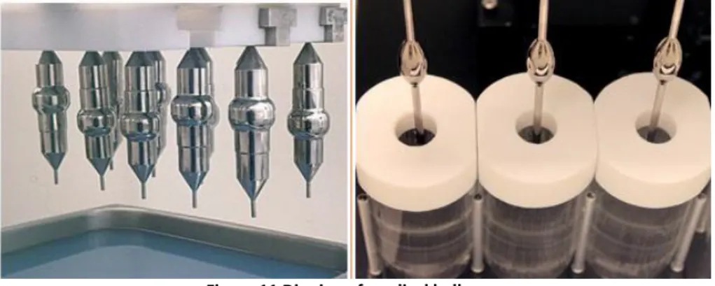
Dip molding of polyurethane and silicone is a relatively recent development. To dip mold a product, a mandrel in the shape of the object being molded is heated, dipped into the resin solution, then removed from the dipping tank. Mandrels can be machined from metal or formed from other materials. Metal is typically used for high-volume production. Glass
22 mandrels produce a very smooth surface but are challenging to use because of their fragility. The mandrel should be lowered gradually into the solution to avoid solvent gassing or bubbles in the solution, which can result in pinholes and weakness in the finished product.
Figure 11 Dipping of medical balloons
After dipping, the thin coating of the polymer that remains on the surface of the mandrel is allowed to cure, then is stripped off as a finished product.
Dip moulding is a cost-effective process for low-volume production of thin-film products, offering consistent wall thickness and uniformity, relatively low tooling costs, and fast setup for new product development.
3.3.4 Assembly Techniques
Epoxies were commonly used in catheter assemblies thanks to their very high performance. However they require long cure cycles or elevated cure temperatures and additional facilities dedicated for thus use. As a result, the use of epoxies in catheter subassemblies has often been replaced by the next alternatives:
Adhesives that can be cured on demand through exposure to ultraviolet light
Thermal welding of mating parts. This is accomplished via localized heating of certain materials (for example, Pebax and urethanes), which causes them to reflow and create a integral adhesive bond for the surrounding parts
Elimination, in some cases, of the use of adhesives altogether through innovative processes. For example, variable-stiffness catheter products can be manufactured as a continuous process
Surface modification in the form of chemical etching is required for those non stick materials as PTFE.
3.3.5 Component Outsourcing
Many medical device manufacturers outsource more subassembly to component manufacturers. Additional operations, typically requested from component manufacturers, include:
Cutting to exact length tolerances of non-braided tubing products.
Cutting to length of braided components in which the tip is non-deformed and the braid wires are embedded in the tubing product (non-frayed).
Secondary operations such as flaring, tipping, hubbing, hole drilling/punching, curve forming, and ID/OD tube tapering.
23 Problems with outsourcing subassembly operations can often be minimized by requiring that the component manufacturer have a good quality system in place. ISO certification of quality systems (ISO 13485) is fast becoming a requirement for medical component suppliers.
3.3.6 Sterilization Methods
The first step is deciding whether to design instruments to be reusable or whether to make them disposable. The material requirements for each instrument are quite different. Reusable instruments are most likely going to be steam sterilized. For this type of application, manufacturers should select plastic resins that can be autoclaved. It's important to note, however, that autoclavable resins are much more expensive than those that can be used for disposables.
An important issue concerns the terminal sterilization method used for the finished catheter device. Many catheter manufacturers are tending to favor the use of E-beam or gamma irradiation over ethylene oxide gas. The preference for high-energy sterilization has the result of eliminating the use of some fluoropolymer materials, such as fluorinated ethylene propylene (FEP) or polytetrafluoroethylene (PTFE) in catheter assemblies. This can compromise the finished devices' performance, since equivalent substitutes have not been found that offer all of the performance attributes of these two materials.
Once cross-linked into the desired configuration, silicone (6) catheters are thermally stable (reported operating range from -80 °C to +230 °C), remaining essentially unaffected by repeated autoclaving. They can usually be dry-heat sterilized as well.
Specific requirements for documentation and validation of processes for sterile medical devices are shown in the ISO 11137-1, 3 (Table 1). In Annex II, some tables of different materials with the associated possible sterilization methods are enclosed.
3.4 Regulation
The process of design of a MDs should work with certification proactively. The key determinant for approving a MD to be marketed is that it must be safe and effective. There are a variety of mechanisms to prove a MD is safe and effective and they will be investigated. When placing a MD on the market the manufacturer must have demonstrated through the use of appropriate conformity assessment procedures that the device complies with the Essential Principles of Safety and Performance of MDs (Table 1). Any of the phases in Figure 3 can affect them. The scientific principles upon which a device is based are fundamental: the more complex the device, the higher the risk of user error. Soundness of concept and adequacy of design, construction, and testing (including verification, validation and clinical trials) require analysis to ensure that design parameters and performance characteristics do not impose unwarranted risks.
Good, functional medical devices are produced when the manufacturing process is adequately managed. This consideration has led to the development of good manufacturing practice (GMP) for drugs, biological products and medical devices.
24 In Table 1 there is a short list of the principal regulations to follow in the design of MDs. The first is the generic EMDD, the primary approach to the world of MD development.
Regulation Directive
(EMDD) European Medical Device Directive 2007/47
(AIMD) Active implantable 90/385/EEC
(IVD) In vitro diagnostic 98/79 CEE
Medical electrical equipment IEC 60601 Application of risk management to medical devices ISO 14971 Quality management systems - Requirements for regulatory purposes ISO 13485-13488
ISO 14969 Fundamental aspects of safety standards for medical electrical equipment IEC/TR 60513
Biological evaluation of medical devices ISO 10993 Clinical evaluation of medical devices for human subjects ISO 14155 Guidance on the selection of standards in support of recognized essential principles
of safety and performance of medical devices
ISO 16142
Packaging for terminally sterilized medical devices ISO 11607 Sterilization of medical devices ISO 11135, 11137,
11138, 11140 Table 1 Principal regulations for MD design and development
Clinical evaluation (Table 1) is the assessment and analysis of clinical data pertaining to a MD in order to verify the clinical safety and performance of the device . It is an ongoing process conducted throughout the life cycle of a MD. The Clinical Evaluation can be based on clinical data derived from literature or based on data related to the specific device. It’s mandatory to specify the criteria for the evaluation of the data (description of the methods). The clinical evaluation is required for all the classes of devices, Class I included. For active implantable devices, Class III and no active implantable devices clinical investigations are required. The absence of clinical data has to be duly justified. The clinical evaluation has to be updated on the basis of a post market surveillance plan.
3.4.1 Certification aspects: definitions and classification
MD means any instrument, apparatus, appliance, material or other article, whether used
alone or in combination, including the software necessary for its proper application intended by the manufacturer to be used for human beings for the purpose of:
Diagnosis, prevention, monitoring and treatment of disease or disability
Diagnosis, monitoring, treatment, alleviation of or compensation for an injury or handicap
Investigation, replacement or modification of the anatomy, or of a physiological process
Control of conception.
In the classification and certification of a MD the manufacturer must follow the directions of Directive 2007/47.
All the considerations summarized in Directive 2007/47/EEC are mandatory steps for the manufacturer to obtain the CE mark on devices manufactured on his behalf. There are many components that contribute in parallel with the release of the CE mark as in Figure 12.
25
Figure 12 Steps to CE mark
A simple set of classification rules based on technical features of MDs existing now and in the future is impossible, because of the vast number and the changing nature of variables involved. The human body, however, is a relatively unchanging element of the equation. The European legislator established therefore a classification concept which is essentially based on potential hazards related to the use and possible failure of devices taking account of technology used and of health policy considerations. The classification rules (see ) are based on terms related to duration of contact with the patient, degree of invasiveness and the part of the body affected by the use of the device. These terms are defined in Section I of Annex IX of the directive 2007/47.
Concepts of duration such as transient, short term and long term are defined in terms of continuous use. Continuous use must be understood as an uninterrupted actual use for the intended purpose.
Any device which, in whole or in part, penetrates inside the body, either through a natural body orifice or through the surface of the body is an invasive device. A surgically invasive device always implies that it enters through an artificially created opening. The concept “act by converting energy” includes conversion of energy in the device and/or conversion at the interface between the device and the tissues or in the tissues.
The derived classes of MDs are:
Class I: non-invasive devices, i.e. those which do not come into contact or interact with the body;
Class IIa: invasive short-term devices, used through natural orifices of the body and invasive surgical for temporary use;
Class IIb: short term surgical invasive devices
26 3.5 Quality system
Deming in the 1950's proposed that business processes should be analyzed and measured to identify sources of variations that cause products to deviate from customer requirements. He recommended that business processes be placed in a continuous feedback loop so that managers can identify and change the parts of the process that need improvements. This continuous processcan be summarized in a diagram commonly known as the PDCA cycle for Plan, Do, Check, Act:
Figure 13 PDCA diagram
The law outlines general requirements for MD quality system management, covering issues such as design, production, installation, and sales. A Quality System is defined as the organizational structure, responsibilities, procedures, processes and resources needed to implement quality management. The international quality system standards for MDs are issued by the International Organization for Standardization (ISO) (ISO13485:1996 and ISO13488:1996). ISO13485:1996 includes all the elements of ISO9001:1994 plus a set of minimum supplementary requirements for MDs.
Similar to the ISO 9001:2000 standard(11), ISO 13485:2003 standard for medical device manufacturers has a strong focus on customer satisfaction and improvement, but with an added focus on safety. This explains why ISO 13485:2003, unlike ISO 9001:2000 requires medical device companies to maintain a risk management system.
MDs should be designed and manufactured in such a way that, when used under the conditions and for the purposes intended and, where applicable, by virtue of the technical knowledge, experience, education or training of intended users, they will not compromise the clinical condition or the safety of patients, or the safety and health of users or, where applicable, other persons, provided that any risks which may be associated with their use constitute acceptable risks when weighed against the benefits to the patient and are compatible with a high level of protection of health and safety.
Manufacturers of MDs have to face many challenges to enter the global medical technology market(11). Growing competition requires frequent design changes, shorter time to market, assembly of small parts with complex geometry and tight tolerances, and difficult to work with materials such as titanium and silicone, just to mention a few.
27 The cost of fixing a single error in a device increases exponentially with the discovery time. Thus, the earlier a problem can be identified the more money a company will save; so the design and testing phases are crucial for saving costs.
Design controls (Figure 14) are a component of a comprehensive quality system that covers
the life of a device. Design control begins with development and approval of design inputs, and includes the design of a device and the associated manufacturing processes (12). A specific focus is mandatory on the controls in the work environment to ensure product safety : clean rooms, machines, including also the procedure for cleaning parts coming from external providers.
Figure 14 Application of Design Controls to Waterfall Design Process
The production of the developed devices has been prevalently outsourced but in all cases sufficient evidence has been given in the technical file about the competence of the subcontractor to undertake supply of some parts, material or service in relation to the medical device in question (as said in (13)).
3.6 Risk Management
Risk management principles should be applied throughout the life cycle of medical devices and used to identify and address safety issues. The current approach to device safety is to estimate the potential of a device becoming a hazard that could result in safety problems and harm. This estimate is often referred to as the risk assessment.
In general, risk management(14) can be characterized by phases of activities:
Determination of levels of risk that would be acceptable in the device
Risk analysis
Risk evaluation
Risk control and monitoring activities.
The procedures to determine risk acceptability criteria comes from an analysis of the experience with similar medical devices or research on what appears to be currently accepted
28 risk levels by regulators, users, or patients, given the benefits derived from diagnosis or treatment with the device.
The risk analysis starts with identifying hazards that may occur due to characteristics or properties of the device during normal use or foreseeable misuse. The ISO 14971 is an international standard for manufacturers of medical devices. It specifies a process through which the manufacturer can identify hazards associated with a medical device, estimate and evaluate the risks associated with these hazards, control these risks, and monitor the effectiveness of that controls.
The functional analysis is the starting point and can be carried out using the ISO 14971; questions that can be used to identify medical device characteristics that could impact on safety are presented (pg.83 and 119).
Hazards typically considered in risk analysis include:
Chemical hazards (e.g., toxic chemicals)
Mechanical hazards (e.g., kinetic or potential energy from a moving object)
Thermal hazards (e.g., high temperature components)
Electrical hazards (e.g., electrical shock, electromagnetic interference (EMI))
Radiation hazards (e.g., ionizing and non-ionizing)
Biological hazards (e.g., allergic reactions, bio-incompatibility, and infection)
Use related hazards.
The comparison between estimated risks and risk acceptability criteria will determine an appropriate level of risk reduction, if necessary. The combination of risk analysis and risk evaluation is called risk assessment.
Risk control activities should begin as early as design input and continue through the design and development process, manufacturing, distribution, installation, servicing and throughout the medical device life cycle.
The objective of risk management is rarely to eliminate all risk, but rather to reduce risk to an acceptable level while maintaining feasibility and functionality. Risk management activities should begin as early as possible in the design and development phase, when it is easier to prevent problems rather than correcting them later.
After release of the device to market, risk management activities should be linked to quality management processes, for example, production and process controls, corrective and preventive actions, servicing and customer feedback. In Annex III a flow chart for the risk management activities in design and development has been enclosed.
The specific performance of the device must be analyzed for each conceivable failure, and ranked by probability and consequence of that failure. In order to identify the risk acceptability, existing criteria (i.e. already indentified for similar products) can be used or determined using the following methods: Failure Mode and Effect Analysis (FMEA5), Fault
5
The FMEA analysis is a regulated process (ISO 13485 and 9001) detailing the failure mode, its causes, its effects, the frequency of occurrence, the severity of occurrence and the actions to mitigate the effects.
29 Tree Analysis (FTA), Hazard and Operability Study (HAZOP). When the risk is unacceptable, some additional methods cha be used:
1. indirect methods (i.e., design modification),
2. direct methods (i.e., in case of radiation, protections or screens)
3. description methods (i.e., device application description or prescription) 4. re-definition of the intended use.
3.6.1 The methodology of ISO 14971
The methodology for creating and updating the technological risk analysis for a general product can be summarised in the next steps, as parts in Analysis of Technological Risk:
identification of a “risk”, defined as the chance to have a negative outcome of the project or of one of its activities, related to events – “Unwanted events UE” - that may be foreseen. The name and a brief description of the impact related to the risk must be reported
for the identified risk, the probability of occurrence must be estimated according to the probability scale of the sub-table “Risk Assessment Criteria”. This value must be reported in column “Probability - P” (Annex III)
the negative “impact level – IP” that may affect the project outcomes in case the identified risk occurs must be estimated according to the impact level scale of sub-table “Risk Assessment Criteria”. This value must be reported in column “Impact Level”
the probability and the impact level must be multiplied together in order to fill the column labelled “Risk Estimation”
once the risk has been estimated, the “Risk Estimation” value must be compared with the numerical values of table “Measures Assessment Criteria”. This will be useful in order to decide the need of proper measures for decreasing the risk. If the “Risk Estimation (RE)” value falls within the:
“red” zone (“Risk Estimation” ≥ 18), then measures must be introduced to decrease the “Risk Estimation” down to a value that falls within the green or, at least, the yellow zones;
“yellow” zone (5 ≤ “Risk Estimation” < 18), then measures may be introduced to decrease the “Risk Estimation” down to a value that falls within the green zone;
“green” zone (“Risk Estimation” < 5) then no measures are required.
according to point 5 (in cases 5.a or 5.b) measures must or may be introduced. The proper measures, once identified, must be described in the row named “Measures and contingency”. This has to be placed in the column corresponding with the level of probability of occurrence(EI).
if Measures have been introduced and applied, the new probability and impact level values named in the “Probability after Measures” respectively the Probability after Measures and the Impact Level after Measures must be multiplied together in order to fill the column , labelled “Risk Estimation after Measures or Residual Risk
- RRE”. This value must fall within the green or, at least, the yellow zones
30
4 Muneretto
6Beam Navigation device
A preliminary study for the development of a new device for minimally invasive intervention for the treatment of atrial fibrillation has been here reported. A proof of concept will be presented.
4.1 Analysis of the medical background
Normally with each heartbeat, the electrical impulse begins at the sinoatrial (SA or sinus) node in the right atrium. The SA node produces the electrical impulses that set the rate and rhythm of the heart beat. The electrical activity (Figure 15,left) spreads through the walls of the atria and causes them to contract. The electrical impulse then crosses the AV node and spreads down to the ventricles, causing them to contract. This generates the heart beat.
Atrial fibrillation (AF, Figure 15 right) is a supraventricular tachyarrhythmia characterized by disorganized atrial electrical activity and progressive deterioration of atrial electromechanical function. Electrocardiographic manifestations(15) of atrial fibrillation include absence of sinus P waves (atrial impulse); rapid oscillations (or fibrillatory waves) that vary in amplitude, frequency, and shape; and an irregular ventricular response. AF may occur in isolation or in association with other arrhythmias, most commonly atrial flutter or atrial tachycardia. In AF, various regions of the atrial wall pulse 400-600 times per minute and the ventricular rate is determined by the interaction between the atrial activity and the filtering function of the atrioventricular node.
Figure 15 Electrical System of the Heart (left) Atrial Fibrillation (right)
Abnormalities in the heart's electrical impulses in patients with AF cause blood to be pumped improperly, resulting in pooling or clotting. If a blood clot moves to an artery in the brain, AF can lead to stroke. AF is also associated with increased risk of congestive heart failure and cardiomyopathy (heart muscle disease).
AF is the most common arrhythmia in clinical practice, accounting for approximately one-third of hospitalizations for cardiac rhythm disturbances. Most data regarding the epidemiology, prognosis, and quality of life in AF have been obtained in the United States and western Europe. It has been estimated that 2.2 million people in America and 4.5 million in the
6