ORIGINAL PAPER
Immobilization of nanobeads on a surface to control the size,
shape, and distribution of pores in electrochemically generated
sol
–gel films
Michela Ciabocco&Mario Berrettoni&Silvia Zamponi&
James A. Cox
Received: 19 October 2014 / Revised: 7 December 2014 / Accepted: 9 December 2014 # Springer-Verlag Berlin Heidelberg 2014
Abstract Electrochemically assisted deposition of an ormosil film at a potential where hydrogen ion is gener-ated as the catalyst yields insulating films on electrodes. When the base electrode is modified with 20-nm poly (styrene sulfonate), PSS, beads bound to the surface with 3-aminopropyltriethoxysilane (APTES), and using (CH3) 3SiOCH3as the precursor, the resulting film of organical-ly modified silica (ormosil) has cylindrical channels that reflect both the diameter of the PSS and the distribution of the APTES-PSS on the electrode. At an electrode modi-fied by a 20-min immersion in 0.5 mmol dm−3 APTES followed by a 30-s immersion in PSS, a 20-min electrol-ysis at 1.5 V in acidified (CH3) 3SiOCH3 resulted in an ormosil film with 20-nm pores separated by 100 nm. Cyclic voltammetry of Ru (CN) 64− at scan rates above 5 mV s−1 yielded currents controlled primarily by linear diffusion. Below 5 mV s−1, convection rather than the expected factor, radial diffusion, apparently limited the current.
Keywords Electrode modification . Organically modified silica films . Templated pores . Polystyrene nanobeads . Electrochemical sol–gel processing
Introduction
Modification of electrodes with sol–gel films of controlled porosity is a route to the design of size-exclusion electrodes [1]. The most fundamental step in controlling the porosity is the selection of the pH for the catalysis of sol–gel processing. Acid catalysis yields microporous solids, whereas under basic conditions the product is mesoporous [2]. The difference is related to the relative rates of the hydrolysis and condensation steps of metal alkoxide precursors. When the process is base-catalyzed, a relatively rapid condensation reaction leads to a highly branched product that is less compact than that formed when rapid hydrolysis under acidic conditions dominates. Variation of pH during sol–gel processing, such as changing from an initial acidic to a basic condition, has been used to control the porosity in the formation of sol–gel films [3,4]. The hydrolysis and condensation steps also have been isolated by a high-speed spin-coating approach; when used along with inclusion of surfactants in various ratios with the sol–gel precursor up to eight well-defined structures of mesoporous sol–gel films have been obtained [3].
When the goal is to coat an electrode with a sol–gel film, control of the pH at the surface via an electrochemical reaction is a useful method [5]. As initially reported by Mandler and coworkers [6–8], formation of a sol–gel film on a conducting surface can be performed by applying a sufficiently negative potential to a weakly buffered sol to generate hydroxide ion that catalyzes the deposition. Likewise, at a positive potential, hydrogen ion generation catalyzes the formation of micropo-rous sol–gel films [9–11].
To extend the range of pore size in sol–gel films, templates have been employed. Examples include organized surfactants and latex beads. Inclusion of surfactants at levels above their critical micelle concentration in the sol is a route to obtaining a mesostructured film or monolith [12–15]. As detailed in a
M. Ciabocco
:
M. BerrettoniDipartimento di Chimica Industriale“Toso Montanari”, UOS, Campus di Rimini, Università di Bologna, Rimini, Italy S. Zamponi
Scuola di Scienze e Tecnologie, Università di Camerino, Camerino, Italy
J. A. Cox (*)
Department of Chemistry and Biochemistry, Miami University, Oxford, OH 45056, USA
e-mail: [email protected] DOI 10.1007/s10008-014-2709-3
recent review [16], evaporation-induced and electrochemical-ly assisted self-assembelectrochemical-ly of surfactants on an electrode surface result in structures such as hemi-micelles that serve to tem-plate pores in subsequently formed sol–gel films [17–22].
In fabrication of sol–gel films by electrochemically assisted processing, applying a cathodic potential to an electrode in contact with a surfactant-containing sol, such as cetyltrimethylammonium bromide (CTAB) in pre-hydrolyzed tetraethoxysilane (TEOS), is a route to forming mesoporous channels perpendicular to the electrode surface. The potential field organizes the CTAB on the surface. Pre-hydrolysis of TEOS under acidic conditions causes formation of linear silica chains in the sol. The cathodic potential gener-ates hydroxide ion at the electrode surface; in turn, polycon-densation of the silica chains around the organized CTAB templates results in a film with the fore-mentioned channels. In an analogous manner, adsorption of a sub-monolayer of generation-4 poly (amidoamine) dendrimer (PAMAM) pro-vided a template for ca. 10-nm pores in a sol–gel film on an electrode [11]. This film formation procedure was adapted from Mandler and coworkers [6–8] except that the adsorbed PAMAM premodified the electrode and hydrogen ion gener-ated at a positive potential was the sol–gel processing catalyst [11].
The formation of macroporous sol–gels with sulfonated polystyrene (PSS) beads included in the precursor solution has been reported. Spin-coated films derived from tetramethoxysilane that contained 500-nm PSS beads became macroporous when the PSS was dissolved [23]. In a similar fashion, films were fabricated with a variation in pore size that was imparted via the dimensions of PSS particles in a mixed TEOS, dimethyldiethoxysilane precursor [24]. Additives oth-er than PSS have been used to obtain macroporous sol–gel films. For example, dip casting with a sol that included poly (ethylene glycol) in conjunction with control of pH yielded silica films with a ca. 50 % macropore volume [25].
Electrochemically assisted deposition of a sol–gel film in combination with polystyrene templates has been used previ-ously to achieve films of controlled porosity [26]. A combi-nation of mesopores and macropores in a film derived from TEOS that contained CTAB and polystyrene was achieved when pre-hydrolysis and electrochemically assisted self-assembly [16,21,22] was used [26]. In this case, the sol–gel
was deposited on an indium tin oxide electrode on which a 600–1,000-nm layer of polystyrene colloidal crystals (100-nm diameter) was formed by dip-coating. After aging the depos-ited sol–gel overnight, the CTAB and polystyrene were ther-mally removed at 550 °C. In this manner a film with a mix of ca. 3-nm and 100-nm pores was produced.
We fabricated thin films of organically modified silica with 50-nm pores by combining electrochemically assisted sol–gel processing of a trimethylmethoxysilane precursor with modi-fication of a glassy carbon electrode by electrostatic
attachment of 50-nm PSS beads to a sub-monolayer of 3-aminopropyltriethoxysilane (APTES) [27]. The PSS and APTES were dissolved from the dried film with chloroform. The pore geometry was sufficiently well defined to permit immobilization of electrochemical catalysts within the void volumes using layer-by-layer electrostatic assembly. The resulting modified electrodes were applied to size-exclusion electrocatalytic oxidation of phospholipids in protein-containing media [27]. In contrast to analogous experiments at an electrode without the size-exclusion property, the protein did not passivate the electrode.
The previously fabricated electrode was limited for appli-cations to catalytic, size-exclusion voltammetry by the 50-nm diameter of the resulting pores. Moreover, a systematic meth-od for varying the pore density was not demonstrated. In the present study, 20-nm PSS beads were investigated as tem-plates, and the relationship between coverage of the electrode by APTES-bound PSS and the resulting pore distribution was studied.
Experimental Reagents and materials
The precursor to the formation of the organically modified silica (ormosil) film was trimethylmethoxysilane (99 %) from Sigma-Aldrich (Milwaukee, WI) with 2-propanol (99.5 %) as the diluent (Alfa Aesar, Ward Hill, MA). Prior to electrochem-ically assisted deposition of the ormosil, the electrode surface was modified, first, with 3-aminopropyltriethoxysilane (99 %), APTES, obtained from Sigma-Aldrich (St. Louis, MO) and, second, with 20-nm-diameter sulfonated polysty-rene beads, PSS, obtained in an 8 % (w/v) suspension from the Molecular Probes® unit of Life Technologies Corp. (Eugene, OR). The other chemicals were reagent grade. The water was house-distilled that was further purified with Barnstead NANO Pure II system. Voltammetry was performed with glassy carbon (GC) electrodes, 3.0 mm diameter, obtained from Bioanalytical Systems (West Lafayette, IN). The ormosils imaged by electron microscopy were deposited on indium tin oxide (ITO) sheets from Delta Technologies, Lim-ited (Stillwater, MN). The ITO was cut into ca. 1.5 cm squares, a portion of which was isolated with a 0.5-cm (diameter) ring to serve as the working electrode. The O-ring was held in place by clamping with a pair of Teflon-coated steel plates. A 1-cm cylinder in an opening above the O-ring was connected to a 10-cm3sample cell (Teflon). Methods
The electrodes were modified by the following sequence: chemisorption of APTES, ion-exchange of PSS onto the
positively charged APTES sites, electrochemically assisted deposition of the ormosil, and removal of the APTES and PSS. Unless otherwise stated, the first of these steps was reaction of GC with 0.5–50 mmol dm−3APTES solution in methanol for 20 min. After rinsing, PSS was immobilized on the GC|APTES by immersion in a 1:1 dilution of the com-mercial 20-nm PSS suspension in water for 30 s. The GC|APTES-PSS electrode was rinsed and transferred to an aged (for 60 min) sol that was prepared by mixing 5.0 mL of 0.1 mol dm−3 LiClO4 in 2-propanol with 2.5 mL H2O, adjusting the pH to 5.0 with 0.1 mol dm−3HCl, and slowly adding 2.0 mL of trimethylmethoxysilane. Based on our pre-vious study [27], a potential of 1.5 V vs. Ag | AgCl was applied for 20 min during which the solution was stirred. Copious evolution of gas was not observed under this condi-tion. The electrode was slowly withdrawn while potential was still applied, and the excess sol was removed by capillary action onto a tissue contacted to the electrode casing. The electrode was air-dried overnight, and the APTES-PSS was dissolved in chloroform. After rinsing with fresh chloroform, the film was dried overnight. It should be noted that the potential must be selected to prevent excessive generation of gaseous products. Indeed, the intentional generation of H2has been used to form macropores during electrochemically assisted formation of a sol–gel film [28].
Prior to reuse of the electrodes, the ormosil films were removed by sonication for 10 min in a NaOH solution and polishing the treated surface to a mirror-like surface with an aqueous alumina slurry of different sizes (0.3 and 0.05μm) on a cloth. The restoration of the surface was verified by obtaining the reversible, one-electron oxidation signature for the cyclic voltammetry of 1.0 mmol dm−3 Ru (CN) 64− in 1.0 mol dm−3KCl at 100 mV s−1. The criteria for a clean surface were five replicate cycles with peak current agreement to within 3 % of that at the original bare electrode and a peak separation of 59–65 mV.
All electrochemical measurements were performed on so-lutions that were deaerated with nitrogen gas. The potentials were measured and reported vs. an Ag|AgCl, 3 mol dm−3KCl reference electrode from Bioanalytical Systems (West Lafa-yette, IN).
Instrumentation
The electrochemical experiments were performed with CH Instruments (Austin, TX) Models 400 and 660B systems. Scanning electron microscopy (SEM) was performed with a Zeiss Supra 35VP FEG (Oberkochen, Germany) instrument. The samples were sputter-coated with gold prior to imaging. Pores sizes were determined with Image-Pro® Plus software. Transmission electron microscope (TEM) experiments were performed with a Jeol JEM-2100 electronic microscope work-ing at 200 kV. Attenuated total reflectance (ATR) spectra of
the samples on glassy carbon plates were recorded with a PerkinElmer Spectrum 100 Series FT-IR spectrometer.
Results and discussion
We previously demonstrated that modification of glassy car-bon with APTES to which 50-nm PSS spheres were attached followed by electrochemically assisted deposition of an ormosil yielded a film with 50-nm pores [27]. The results suggested that the APTES and PSS were removed by soaking the electrode in chloroform. In the present study, a comparison of ATR spectra of bare GC, GC modified with APTES and PSS, and the modified electrode after treatment with chloro-form was made. Of importance is that an overnight soaking in chloroform followed by air-drying removed the APTES and PSS to below the detection limit of the instrument. This dissolution process results in open pores in the ormosil-modified electrode.
Except for pore size and the absence of ion-exchange sites, the characteristics of the film were not determined in our previous study [27]. However, from the results, it was hypoth-esized that the pores were cylindrical and comprised the only electroactive portion of the film when electrochemically assisted sol–gel processing was used at a positive potential where the catalyst that is generated is hydrogen ion [27]. That is, the data suggested, first, that the pore shape was a “shad-ow” of the surface-bound species rather than a deposit around the exterior surface of the PSS spheres and, second, that the sol–gel phase was sufficiently compact to block mass trans-port of electroactive species from the solution to the electrode surface by paths other than through the templated pores. In a further extension of our previous studies [27,29], a systematic evaluation of the influence of APTES on the density of the pores was made in this investigation.
Demonstration of the deposition of an ormosil film with 20-nm pores
The initial experiments were to determine whether the meth-odology for fabrication on GC of an ormosil film with 50-nm pores, GC|ormosil (50-nm pores), was applicable to fabrica-tion of films of ormosil (20-nm pores). The procedure in “Methods” section was used except the electrode was ITO
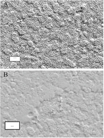
used in some cases. After modification with 0.5 mmol dm−3 APTES and PSS (20-nm), the ITO surface shown in Fig.1a
was obtained. The important feature is that the diameter of the channels at the outer surface of the ormosil (20 nm from Image-Pro Plus® software) is that of the cross section of the PSS templating agent. Image 1B is that of a blank (same conditions as Fig. 1a except APTES was absent); at the resolution of the instrument, no evidence of a pore structure
is observed. The results in Fig.1b demonstrate two points. First, 20-nm PSS does not adsorb to the electrode when it is not modified with APTES. Second, deposition of the ormosil at a positive potential where hydrogen ion is the electrochem-ically generated catalyst of the sol–gel process gives a com-pact film on the electrode. The same results were obtained when GC rather than ITO was the electrode.
The influence of APTES concentration used to modify the electrode on the cyclic voltammetry of Ru (CN) 64− in 1.0 mol dm−3KCl was investigated (Fig.2). Except for the APTES concentration, the conditions were those in Fig.1a. The increase in current with increase in APTES concentration over the range 0–15 mmol dm−3is illustrative of the role of APTES on the population of surface-immobilized PSS nano-particles and, hence, on the resulting pore density. When the electrode was not modified with APTES prior to immersion in PSS, a passivating (non-porous) ormosil film was obtained, which is consistent with the image in Fig.1b. Increasing the APTES concentration to 30 mmol dm−3resulted in only a small increase in peak current for the oxidation of Ru (CN)64−. Either the adsorption isotherm for APTES is nonlinear or the packing
of PSS in a monolayer approaches a limit when 30 mmol dm−3 is used to modify the electrode (Fig.3). The standard deviations of the peak currents for electrodes modified with 0.5, 5.0, 15, and 30 mmol dm−3 APTES are 0.2, 0.1, 0.4, and 0.5 μA, respectively.
A surprising result was observed when 50 mmol dm−3 APTES was used to modify the base electrode. The peak current for the oxidation of Ru (CN)64−drastically decreased (Fig.3). In this case, the standard deviation was 0.2μA. That is, the ormosil film prepared under this condition apparently was not permeable to Ru (CN)64−. One possibility that was considered was whether the APTES surface excess was suffi-cient to form a polymeric film in the acidic environment on the
A
B
__
Fig. 1 SEM image of an ITO electrode modified with APTES and 20-nm PSS. Conditions are in“Methods” with a 0.5 mmol dm−3APTES reacted with an ITO surface for 15 min prior to immersion in PSS. The ormosil was deposited at 1.5 V for 20 min. b Same as a except that no modification of the surface with APTES was done prior to immersion in PSS. The bar represents 100 nm
Fig. 2 Cyclic voltammetry of 1.0 mmol dm−3K4Ru (CN)6at a bare GC;
b GC|ormosil (20-nm pores) that was prepared from 0.5 mmol dm−3 APTES; and c CG|ormosil (20-nm pores) that was prepared from 15 mmol dm−3APTES. Supporting electrolyte, 1.0 mol dm−3KCl; v, 100 mV s−1. Conditions are detailed in“Methods”
Fig. 3 Influence of APTES concentration on pore density (effective electrode area) of GC|ormosil (20-nm pores). The conditions are those in Figs.2b, cexcept the APTES concentration is varied over a wider range
surface when 1.5 V was applied. An electrode was modified with APTES as in Fig. 3, and 1.5 V was applied in the supporting electrolyte (5.0 mL of 0.1 mol dm−3LiClO4in 2-propanol to which 2.5 mL H2O was added; the pH to 5.0 with 0.1 mol dm−3HCl). The current developed in cyclic voltamm-etry under the Fig.3conditions was the same as that at a bare electrode.
Consistent with the electrochemical data in Fig.3, SEM imaging of the surface demonstrated that a compact, nonpo-rous film was formed when 50 mmol dm−3APTES was used to modify the electrode (Fig.4). As described in“Film geom-etry” section, further imaging experiments were performed to
elucidate the reason for deposition of a nonporous ormosil under this condition.
Film geometry
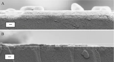
SEM images of cross sections of ormosil films prepared after treatment with 0.5 mmol dm−3 and with 50 mmol dm−3 APTES were compared to determine whether the quantity of
PSS that is immobilized prior to the electrochemically assisted deposition of the ormosil influenced the film thickness (Fig. 5). When 0.5 mmol dm−3 was used to modify the electrode and the film was deposited as described in “Methods”, the thickness was 270 nm. At the higher
concen-tration, the thickness, while too inconsistent to accurately estimate, is generally below 50 nm. Excess PSS that results from a high population of APTES sites on the ITO electrode clearly disrupts the electrochemically assisted processing of (CH3)3SiOCH3. Perhaps when the PSS is tightly packed on the electrode surface or is stacked in a multilayer, the (CH3) 3SiOCH3, which is the precursor to the ormosil, is blocked from reaching the acidified zone at the electrode surface. Instead, the hydrogen ion catalyst must transport across the PSS layer by, for example, site-to-site diffusion. The resulting ormosil film can be predicted to be thinner than when the sol– gel processing occurs directly at the acidified surface, and the PSS will not template a pore structure in that ormosil forms above it.
Attempts to elucidate the pore geometry by SEM imaging of a film cross section were unsuccessful. Instead, a portion of the film was mechanically removed from the electrode and imaged by TEM (Fig. 6). The horizontal image, Fig. 6a, suggests that the pores are cylindrical. These apparent pores do not appear as open cylinders because of an anomaly that occurs because removal of the film skews the film geometry. The vertical image, Fig. 6b, does show open pores at the ormosil surface with a diameter in the 20-nm range.
Influence of the pore structure and distribution on voltammetry
The experiments displayed in Fig.2involving the CV of Ru (CN) 63− as a function of pore density were expanded to elucidate the current-limiting process at the GC|ormosil (20 nm) electrode. First, the influence of scan rate, v, on the peak current, ipa, for the oxidation of Ru (CN) 63− was
__
Fig. 4 SEM image of an ormosil film formed by electrochemically assisted processing at an electrode modified in 50 mmol dm−3APTES for 20 min prior to immersion in 20-nm PSS. Conditions are detailed in “Methods.” The bar represents 100 nm
A
B
Fig. 5 Influence of the APTES concentration on the thickness of the ormosil deposited by an electrochemically assisted process. Shown are SEM images of cross sections of ormosil films deposited onto GC modified by treatment in a 0.5 mmol dm−3 APTES and b 50 mmol dm−3 APTES. Following modification with APTES, adsorption of PSS and deposition of an ormosil were performed as described in the caption to Fig.1. Index bars, 200 nm
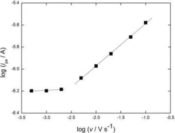
determined (Fig. 7). In the v-range, 5–100 mV s−1, the slope of the plot of log ipavs. v is 0.42, which approaches the theoretical value of 0.5 for a current limited by semi-infinite linear diffusion. Below 5 mV s−1, ipa is nearly independent of v, which generally is an indicator of radial diffusion as the current-limiting process. However, this interpretation is for a conventional electrode where the surface of the electrode directly contacts the bulk solution. The present study is in the category of nanoscale electro-chemistry, which includes both the use of single electrodes at the base of nanopores in various materials and nanoarrays of electrodes. The topic is the subject of a recent review [30].
Of relevance to the present study, White and coworkers have described mass transfer to an electrode at the base of a single nanopore [31, 32]. Here, the nanopore was an inverted cone (where the pore radius is greater than that of the electrode surface). The parameters than must be considered are the following:δ, the diffusion layer thick-ness whereδ≈(2Dt)1/2; ro, radius of the nanopore; and dp,
depth of the nanopore. When δ>10 (ro+ dp) [31], the cur-rent is limited by radial diffusion to the junction of the pore with the bulk solution, in which case it reaches steady state. In terms of the present study, if the prediction for a single nanopore applies to the array in the ormosil, the current that is developed in CV for the oxidation of Ru (CN)63−would reach a steady state value that is indepen-dent of v as long as the pores were separated sufficiently to not have overlapping diffusion fields. In Fig.7, rois 10 nm and dpis ca. 200 nm. Converting v to an experimental time, te x p t, by te x p t= RT/vF [31, 33] and assuming D ≈ 10−6cm2s−1 yields a prediction of radial diffusion at all v values in Fig.7as long as the diffusion fields surround-ing the pores do not overlap.
The above prediction is not followed at v values >5 mV s−1. That linear diffusion is observed experimentally at v> 5 mV s−1is a result of the array structure of the pores in the ormosil film not meeting the condition of non-overlapping diffusion fields. Designating xsepas a representative distance between the pores, ifδ>xsep, the diffusion layers around the pores overlap in which case linear diffusion to the outer
Fig. 6 Horizontal (a) and vertical (b) TEM images of a portion of the film obtained using
0.5 mmol dm−3APTES to modify the electrode. The experimental conditions are described in “Methods”. Index bars, 50 nm
Fig. 7 Evaluation of the current-limiting process in the cyclic voltammetry of 1.0 mmol dm−3K4Ru (CN)6in 1.0 mol dm−3KCl at
GC|ormosil (20-nm pores) where the deposition was performed as in Fig.1aexcept the electrode was GC rather than ITO
Fig. 8 Chronoamperometry of 1.0 mmol dm−3 K4Ru (CN) 6 in
1.0 mol dm−3 KCl at GC|ormosil (20 nm) prepared as described in Fig.1a. At t=0, the applied potential, Eapp, was 0.4 V; at t>0, Eapp=0.9 V
surface of the ormosil film limits the current alone or in combination with radial diffusion. The slope of 0.42 of the portion of Fig.7at v>5 mV s−1indicates that linear diffusion is dominant in this region. Under the conditions used to deposit the ormosil in Fig.7, xsep≈100 nm. Thus, even at the highest v in Fig.7, 100 mV s−1, at whichδ=2×10⁴nm, the diffusion layers of the array overlap. Linear diffusion because of this overlap previously was observed with films of poly (styrene) prepared from a diblock copolymer of poly (styrene) and poly (methylmethacrylate) where 10-nm (radius) pores were separated by an average of 36 nm and v was below 100 mV s−1 [34]. As in the present study, the depth of the pores was much less than the thickness of the diffusion layer. Extending this analysis to interpret the apparent onset of radial diffusion at v<5 mV s−1 in Fig. 7 results in an anomaly in that linear diffusion should continue to be the current-limiting process. For example, at 1 mV s−1, the value of texptis approximately 26 s. When D is approxi-mated as 10−6cm2s−1, the value ofδ is about 7×10⁴nm, which greatly exceeds xsep. The factor that is not accounted for in this entire treatment is convection. In that the exper-iments were performed with the electrochemical cell on the bench top rather than isolated from environmental factors will cause some degree of convection, so maintaining a diffusion-limited process for a time such as 26 s is not realistic. Indeed, the onset of convection is probably at times in the range 1–5 s. Chronoamperometry corroborates this interpretation. As shown in Fig.8, the current for the oxidation of Ru (CN) 63− approaches steady state as t approaches 1 s.
Overall, these data suggest that radial diffusion at a nanoscale is unlikely to be attained at slow scan rates unless the electrochemical cell is isolated from environ-mental causes of convection. At the nanoscale, this prob-lem is certainly more significant that with micron-scale electrodes and/or arrays. Nevertheless, radial diffusion can be achieved. Mirkin and coworkers [35] obtained steady-state (current plateau) CVs of 2 mmol dm−3 Ru (NH3)63+at an 850-nm Ag electrode in a nanowell formed by etching the Ag held in a glass capillary, and the anodic and cathodic current plateaus were superimposed at 50 mV s−1.
Given that the envisioned application of these electrodes is to fabricate arrays that serve as catalytic, size-exclusion films [1], future work will be aimed at developing nanoarrays with pore diameters in the 10–20 nm range and pore separation sufficient to provide non-overlapping diffusion layers. In these regards, methods such as ion-milling have been used to vary the separation distances but yield pores with diameter above 150 nm [36]. In contrast, aluminum oxide films yield cylindrical pores with diameters down to 20 nm [37] but are not separated by the distances needed for our objectives.
Conclusions
Electrochemically assisted deposition of an ormosil film from (CH3)3SiOCH3onto a surface modified by a distribution of 20-nm PSS beads resulted in a film with cylindrical pores that formed above the APTES-immobilized PSS. The distribution of the pores was controlled via the surface coverage of GC or ITO by APTES, which in turn was determined by its concen-tration during the modification of the base electrode. As the concentration of APTES in the modification medium was increased (and, hence, the quantity of PSS deposited), the pore density in the ormosil film increased initially, but a point was reached where a non-porous ormosil was deposited. Imaging the electrode modified with APTES and PSS showed that the deposition of a non-porous ormosil film occurred when the APTES coverage resulted in the immobilization of densely packed PSS. The oxidation of Ru (CN) 63− at an electrode modified with a nanoarray of pores gave a current limited primarily by linear diffusion. When CV at scan rates below 5 mV s−1was performed, a steady-state current was devel-oped; however, rather than reflecting an onset of radial diffu-sion in this time domain, the steady-state current was due to convection caused by environmental factors.
Acknowledgments The work was supported in part by a grant to J.A.C. from the US National Institutes of Health through R15GM087662-01.
References
1. Cox JA (2011) J Solid State Electrochem 15:1495–1507
2. Brinker CJ, Scherer GW (1990) Sol-gel science: the physics and chemistry of sol-gel processing. Academic, San Diego
3. Lee UH, Yang JH, Lee HJ, Park JY, Lee KR, Kwon YU (2008) J Mater Chem 18:881–1888
4. Sheffer M, Groysman A, Mandler D (2003) Corros Sci 45:2893– 2904
5. Etienne M, Guillemin Y, Grosso G, Walcarius A (2013) Anal Bioanal Chem 405:1497–1512
6. Shacham R, Avnir D, Mandler D (1999) Adv Mater 11:384–388 7. Shacham R, Avnir D, Mandler D (2004) J Sol-Gel Sci Technol 31:
329–334
8. Shacham R, Mandler D, Avnir D (2004) Chem Eur J 10:1936–1943 9. Wandstrat MM, Spendel WU, Pacey GE, Cox JA (2007)
Electroanalysis 19:139–143
10. Cox JA, Wiaderek KM, Mehdi BL, Gudorf BP, Ranganathan D, Zamponi S, Berrettoni M (2011) J Solid State Electrochem 15: 2409–2417
11. Ranganathan D, Zamponi S, Berrettoni M, Mehdi BL, Cox JA (2010) Talanta 82:1149–1155
12. Tanev PT, Pinnavaia TJ (1995) A neutral templating route to meso-porous molecular sieves. Science 267:865–857
13. Walcarius A, Sibottier E, Etienne M, Ghanbaja J (2007) Nature Mater 6:602–608
14. Goux A, Etienne M, Aubert E, Lecomte C, Ghanbaja J, Walcarius A (2009) Chem Mater 21:731–741
16. Etienne M, Guillemin Y, Grosso D, Walcarius A (2013) Anal Bioanal Chem 405:1497–1512
17. Brinker CJ, Lu YF, Sellinger A, Fan HY (1999) Adv Mater 11:579– 585
18. Miyata H, Kawashima Y, Itoh M, Watanabe M (2005) Chem Mater 17:5323–5327
19. Ghosh K, Vyas SM, Lehmler HJ, Rankin SE, Knutson BL (2007) J Phys Chem B 111:363–370
20. Wei TC, Hillhouse HW (2007) 23:5689–5699
21. Poltorak L, Herzog G, Walcarius A (2013) Electrochem Comm 37: 76–79
22. Herzog G, Vodolazkaya NA, Walcarius A (2013) Electroanalysis 25: 2595–2603
23. Kanungo M, Collinson MM (2004) J Chem Soc Chem Commun 548–549
24. Kanungo M, Deepa PN, Collinson MM (2004) Chem Mater 16: 5535–5541
25. Carrasquilla C, Li Y, Brennan JD (2011) Anal Chem 83:957–965
26. Etienne M, Sallard S, Schröder M, Guillemin Y, Mascotto S, Smarsly BM, Walcarius A (2010) Chem Mater 22:3426–3432
27. Mehdi BL, Rutkowska IA, Kulesza PJ, Cox JA (2013) J Solid State Electrochem 17:1581–1590
28. Li J, Xiao FN, Xia XH (2012) Analyst 137:5245–5250
29. Rutkowska IA, Sek JP, Mehdi BL, Kulesza PJ, Cox JA (2014) Electrochim Acta 122:197–203
30. Murray RW (2008) Chem Rev 108:2688–2720
31. Zhang B, Zhang Y, White HS (2004) Anal Chem 76:6229–6238 32. Zhang B, Zhang Y, White HS (2006) Anal Chem 78:477–483 33. Bard AJ, Faulkner LR (2001) Electrochemical methods, 2nd edn.
Wiley, New York
34. Li Y, Maire HC, Ito T (2007) Langmuir 23:12771–12776
35. Noël JM, Velmurugan J, Gökmeşe E, Mirkin MV (2013) J Solid State Electrochem 17:385–389
36. Lanyon YH, De Marzi G, Watson YE, Quinn AJ, Gleeson JP, Redmond G, Arrigan DWM (2007) Anal Chem 79:3048–3055 37. Miller CJ, Majda M (1985) J Am Chem Soc 107:1419–1420