The
Eur
o
p
e
an
Uni
o
n
I
n
or
de
r
t
o
pr
omot
e
publ
i
c
e
duc
a
t
i
on
a
nd
publ
i
c
s
a
f
e
t
y,
e
qua
l
j
us
t
i
c
e
f
or
a
l
l
,
a
be
t
t
e
r
i
nf
or
me
d
c
i
t
i
ze
nr
y,
t
he
r
ul
e
of
l
a
w,
wor
l
d
t
r
a
de
a
nd
wor
l
d
pe
a
c
e
,
t
hi
s
l
e
ga
l
doc
ume
nt
i
s
he
r
e
by
ma
de
a
va
i
l
a
bl
e
on
a
nonc
omme
r
c
i
a
l
ba
s
i
s
,
a
s
i
t
i
s
t
he
r
i
ght
of
a
l
l
huma
ns
t
o
know
a
nd
s
pe
a
k
t
he
l
a
ws
t
ha
t
gove
r
n
t
he
m.
≠
EDI
CT
OF
GOVERNMENT
±
EN 1994-1-1 (2004) (English): Eurocode 4: Design of
composite steel and concrete structures – Part 1-1: General
rules and rules for buildings [Authority: The European Union
Per Regulation 305/2011, Directive 98/34/EC, Directive
EUROpAISCHE NORM
December 2004ICS 91.010.30; 91.080.10; 91.080.40
English version
Supersedes ENV 1994-1-1:1992
Incorporating corrigendum April 2009
Eurocode 4: Design of composite steel and concrete structures
-Part 1-1: General rules and rules for buildings
Eurocode 4: Calcul des structures mixtes acierbeton -Partie 1-1: Regles generales et regles our les batiments
This European Standard was approved by CEN on 27 May 2004.
Eurocode 4: Bemessung und Konstruktion von Verbundtragwerken aus Stahl und Beton - Teil1-1: Allgemeine Bemessungsregeln und Anwendungsregeln fUr
den Hochbau
CEN members are bound to comply with the CEN/CENELEC Internal Regulations which stipulate the conditions for giving this European Standard the status of a national standard without any alteration. Up-to-date lists and bibliographical references concerning such national standards may be obtained on application to the Central Secretariat or to any CEN member.
This European Standard exists in three official versions (English, French, German). A version in other language made by translation under the responsibility of a CEN member into its own language and notified to the Central ~"""r",,1!""rl:::lt has the same status as the official versions.
CEN members are the national standards bodies of Austria, Belgium, Cyprus, Czech Republic, Denmark, Estonia, Finland, France, Germany, Greece, Hungary, Iceland, Ireland, Italy, Latvia, Lithuania, Luxembourg, Malta, Netherlands, Norway, Poland, Portugal, Slovakia, Slovenia, Spain, Sweden, Switzerland and United Kingdom.
EUROPEA"N COMMITTEE FOR STAl\DARDIZATI00i COMIT UROPEEN DE l\ORMALISATION EUROpAISCHES KOMlTEE FeR NORI\lUNG
Management Centre: rue de Stassart, 36 B-1050 Brussels 2004 CEN All rights of exploitation in any form and by any means reserved
worldwide for CEN national Members.
Contents
Page
Fore\vord... ... 8
Section 1 Gelleral ... 12
1.1 Scope ... 12
1.1.1 Scope of Eurocode 4... 12
1.1.2 Scope of Part 1. 1 of Eurocode 4.. .. .. . . . .. .. .. . .. . .. . .. .. .. . . .. .. . . .. .. . .. .. . .. .. .. .. .. .... 12
1.2 Norl11ative referel1ces.. . ... . ... .. ... . . ... ... ... . .. ... ... 13
1.2.1 General reference standards... 13
1.2.2 Other reference standards ... 13
1.3 AssutnptiollS ... 14
1.4 Distinction between principles and application rules ... 14
1.5 Definitions... ... 14
1.5.1 Getleral... 14
1.5.2 Additional ternlS and definitions used in this Standard... .. ... . ... . .. ... ... .. .... 14
1.6 Symbols... 15
Section 2 Basis of design... 22
2.1 Requirenlents... ... 22
2.2 Principles of linlit state design... .. ... .. ... ... .. ... . . ... . .. . ... . . . . .. .... .. 23
2.3 .Basic variables ... 23
2.3.1 Actions and environmental influences. . . . ... . .. ... ... ... 23
2.3.2 Material and product properties ... 23
2.3.3 Classification of actions ... 23
2.4 Verification by the partial factor nlethod ... 23
2.4.1 Desigll values... 23
2.4.1.1 Design values of actions ... 23
2.4.1.2 Design values of nlaterial or product properties ... 23
2.4.1.3 Design values of geon1etrical data ... 24
2.4.1.4 Design resistances ... 24
2.4.2 Conlbillation of actions ... 24
2.4.3 Verification of static equilibrium (EQU)... 24
Section 3 Materials. ... ... 24 3.1 Concrete... 24 3.2 Reil1forcing steeL... .. ... . .. ... . . . .. . . .. ... ... ... .. ... 25 3.3 Structural steel... 25 3.4 Conllecting devices... 25 3.4.1 Gelleral ... 25
3.4.2 Headed stud shear connectors ... . 3.5 Profiled steel sheeting for composite slabs in buildings ... 25
Section 4 Durabilit)!... 25
4.1 Gel1eral ... 25
Section 5 Structural analysis... ... ... ... ... ... ... ... ... .... .... ... 26
5.1 Stluctural modelling for analysis... . . ... .. . .. . . . ... . . . .. .. .. . . ... . . .. .. . . .. . . .. . ... 26
5.1.1 Stluctural nl0delling and basic assunlptions... 26
5.1.2 Joint nl0delling ... 26
5.1.3 Ground-structure interaction... 26
5.2 Structural stability... 27
5.2.1 Effects of defonned geonletry of the stlucture... 27
5.2.2 Methods of analysis for buildings... 27
5.3 Ill1perfectiollS... 28 5.3.1 Basis ... 28 5.3.2 Imperfections in buildings... 28 5.3.2.1 Gelleral ... 28 5.3.2.2 Global inlperfections ... 29 5.3.2.3 Men'lber imperfections... 29
5.4 Calculation of action effects ... 29
5.4.1 Methods of global analysis ... 29
5.4.1.1 General ... 29
5.4.1.2 Effective width of flanges for shear lag ... 29
5.4.2 Linear elastic analysis ... 30
5.4.2.1 Gelleral ... 30
5.4.2.2 Creep and shrinkage... 31
5.4.2.3 Effects of cracking of concrete ... 32
5.4.2.4 Stages and sequence of constluction... 33
5.4.2.5 Tenlperature effects ... 33
5.4.2.6 Pre-stressing by controlled ilnposed deformations ... 33
5.4.3 Non-linear global analysis... 33
5.4.4 Linear elastic analysis with linlited redistribution for buildings ... 34
5.4.5 Rigid plastic global analysis for buildings... 35
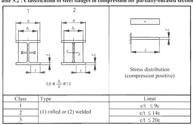
5.5 Classification of cross-sections... 36
5.5.1 General ... 36
5.5.2 Classification of COlllposite sections without concrete encasenlent. ... 37
5.5.3 Classification of cOlnposite sections for buildings with concrete encaselllent.. . . .. . . .. .. . .. ... . .. . .... .. . . ... . . ... . . . . ... . . . .... .. .. . . . .. .. . . . .. . . .. . .. 37
Section 6 Ultimate limit states. . .. . ... ... .. . .. . .. . .. . .. . .. . .. . .. . .. ... . .. . .. . ... .. ... . .. . ... .. . .. . .. . .. . .. . .. . . 38
6.1 Beams ... 38
6.1.1 Beams for buildings ... 38
6.1.2 Effective width for verification of cross-sections ... 40
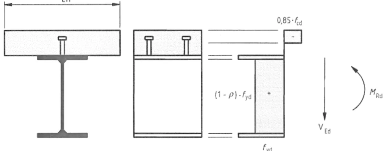
6.2 Resistances of cross-sections of beanls ... .40
6.2.1 Bellding resistallce... 40
6.2.1.1 General... 40
6.2.1.2 Plastic resistance nl01nent Mp1,Rd of a cOlnposite cross-section.. .. . . . ... . ... . . ... 40
6.2.1.3 Plastic resistance monlent of sections with partial shear connection in buildings... 42
6.2.1.4 Non-linear resistance to bending... 43
6.2.1.5 Elastic resistance to bending... 44
6.2.2 Resistance to vertical shear. ... .. .... .... . .. ... .. .. .... ... ... .. .. .. .... .. .. .. .. ... 45
6.2.2.1 Scope... 45
6.2.2.3 Shear buckling resistance ... 45
6.2.2.4 Bending and vertical shear.. .... ... ... . .. .. ... ... .... ... ... 45
6.3 Resistance of cross-sections of bean1s for buildings with partial encase111el1t ... 46
6.3.1 Scope ... 46
6.3.2 Bending resistance... 46
6.3.3 Resistance to vertical shear. ... 47
6.3.4 Bending and vertical shear.... ... ... .. . .. ... .. .. . . . ... .. .. . . ... .... . ... . 48
6.4 Lateral-torsional buckling of cornposite beanls ... 48
6.4.1 General ... 48
6.4.2 Verification of lateral-torsional buckling of continuous composite beams with cross-sections in Class l, 2 and 3 for buildings... 49
6.4.3 Simplified verification for buildings without direct calculation... . . ... . . ... . . ... 51
6.5 Tra11sverse forces on webs... 52
6.5.1 Ge11eral ... 52
6.5.2 Flange-induced buckling of webs ... 52
6.6 Shear c011nectio11 ... . 6.6.1 General ... 52
6.6.1.1 Basis of design ... 52
6.6.1.2 Lilnitation on the use of partial shear connection in beams for bllildil1gs ... 53
6.6.1.3 Spacing of shear connectors in beat11s for buildings ... 54
6.6.2 Longitudinal shear force in beanls for buildings ... 55
6.6.2.1 Bean1s in which non-linear or elastic theory is used for resistances of one or 111 ore cross-sections ... 55
6.6.2.2 Bemns in 'which plastic theory is used for resistance of cross-sectioI1S ... 55
6.6.3 Headed stud connectors in solid slabs and concrete encaselnent. ... . 6.6.3.1 Desigl1 resistance... 55
6.6.3.2 Influence of tension on shear resistance ... 56
6.6.4 Design resistance of headed studs used with profiled steel sheeting ill buildings... 56
6.6.4.1 Sheeting with ribs parallel to the supporting beanls ... 56
6.6.4.2 Sheeting with ribs transverse to the supporting bean1s ... 57
6.6.4.3 Biaxial loading of shear connectors ... 58
6.6.5 Detail1ng of the shear connection and influence of execution ... 58
6.6.5.1 Resistance to separation ... 58
6.6.5.2 Cover and concreting for buildings ... 58
6.6.5.3 Local reinforcement in the slab ... 59
6.6.5.4 Haunches other than forn1ed by profiled steel sheeting ... 59
6.6.5.5 Spacing of connectors ... 60
6.6.5.6 Dilnensions of the steel flange ... 60
6.6.5.7 Headed stud connectors ... , ... , ... 60
6.6.5.8 Headed studs used with profiled steel sheeting in buildings ... 61
6.6.6 Longitudinal shear in concrete slabs ... 61
6.6.6.1 Gel1eral ... 61
6.6.6.2 Design resistance to longitudinal shear ... 61
6.6.6.3 Mininlu111 transverse reinforcen1ent. ... 62
6.6.6.4 Longitudinal shear and transverse reinforcen1ent in beatl1S for buildi11gs ... 62
6.7 COlnposite COlU111nS and conlposite conlpression Inenlbers. ... .. ... .. .. ... . . ... 63
6.7.1 General... ... 63
6.7.2 General nlethod of design ... 65
6.7.3 Simplified method of design... 66
6.7.3.1 General and scope... 66
6.7.3.2 Resistance of cross-sections ... 67
6.7.3.3 Effective flexural stiffness, steel contribution ratio and relative slendell1ess ... 69
6.7.3.4 Methods of analysis and menlber inlperfections ... 70
6.7.3.5 Resistance ofnlenlbers in axial cOlnpression ... 70
6.7.3.6 Resistance ofnlenlbers in conlbined cOll1pression and uniaxial bellding ... 71
6.7.3.7 Combined c0111pression and biaxial bending ... 73
6.7.4 Shear connection and load introduction ... 74
6.7.4.1 General... 74
6.7.4.2 Load introduction ... 74
6.7.4.3 Longitudinal shear outside the areas of load introduction ... 77
6.7.5 Detailing Provisions ... 76
6.7.5.1 Concrete cover of steel profiles and reinforcenlent. ... 78
6.7.5.2 Longitudinal and transverse reinforcelnent. ... 78
6.8 Fatigue ... 78
6.8.1 General ... 78
6.8.2 Partial factors for fatigue assessment for buildings ... 79
6.8.3 Fatig"ue strength ... 79
6.8.4 Internal forces and fatigue loadings ... 80
6.8.5 Stresses ... 80 6.8.5.1 Genera]... 80 6.8.5.2 COl1crete ... 80 6.8.5.3 Structural steel ... 80 6.8.5.4 Reillforcenlent... . ... . ... . ... ... . . ... . ... . ... . . . ... . ... . ... 81 6.8.5.5 Shear connection ... 81 6.8.6 Stress ranges ... 82
6.8.6.1 Structural steel and reinforcen1ent ... 82
6.8.6.2 Shear connection... . ... .. ... . ... .... . . ... . . ... .. ... ... ... 82
6.8.7 Fatigue assessn1ent based on n0111inal stress ranges ... 83
6.8.7.1 Structural steel, reinforcelnent and concrete ... 83
6.8.7.2 Shear connection... 83
Section 7 Serviceability limit states ... 84
7.1 General ... 84
7.2 Stresses ... 84
7.2.1 Ge11eral ... 84
7.2.2 Stress limitation for buildings ... 85
7.3 Deforn1ations in buildings ... 85 7.3.1 Deflections ... 85 7.3.2 Vibratiol1 ... 86 7.4 Crackillg of concrete ... 86 7.4.1 General ... 86 7.4.2 Mininlunl reinforcelnent. ... 87
Section 8 Composite joints in frames for buildings... 89
8.1 Scope ... 89
8.2 Analysis, 1110delling and classification ... 90
8.2.1 General ... 90
8.2.2 Elastic global analysis ... 90
8.2.3 Classification of joints ... 90
8.3 Design 111ethods ... 91
8.3 .1 Basis alld scope ... 91
8.3.2 Resistance ... 91
8.3.3 Rotational stiffness ... 91
8.3.4 Rotation capacity ... 91
8.4 Resistance of C0111pOnents ... 92
8.4.1 Scope ... 92
8.4.2 Basic joint conlponents ... 92
8.4.2.1 Longitudinal steel reinforcenlent in tension ... 92
8.4.2.2 Steel contact plate in cOlnpression ... 92
8.4.3 Colunln web in transverse conlpression ... 93
8.4.4 Reinforced cOlnponents ... 93
8.4.4.1 CO]U111n web panel in shear ... 93
8.4.4.2 COIU1l111 web in compression ... 93
Section 9 Composite slabs \vith profiled steel sheeting for buildings ... 94
9.1 General... 94
9.1.1 Scope ... 94
9.1.2 Defil1itions ... 95
9.1.2.1 Types of shear connection ... 95
9.1
Fu11
shear connection am partial shear connection ... 959.2 Detailing provisions ... 96
9.2.1 Slab thickness and reinforcenlent ... 96
9.2.2 Aggregate ... 97
9.2.3 Bearing requirelnents ... 97
9.3 Actions and action effects ... 97
9.3.1 Design situations ... 97
9.3.2 Actions for profiled steel sheeting as shuttering ... 98
9.3.3 Actions for composite slab... 98
9.4 Analysis for inte1l1al forces and nlonlents ... 98
9.4.1 Profiled steel sheeting as shuttering... 98
9.4.2 Analysis of composite slab ... 98
9.4.3 Effective width of conlposite slab for concentrated point and lille loads... 99
9.5 Verification of profiled steel sheeting as shuttering for ultimate linlit states ... 100
9.6 Verification of profiled steel sheeting as shuttering for serviceability lilnit states ... 100
9.7 Verification of conlposite slabs for ultimate linlit states ... 100
9.7.1 Design criterion... ... ... 100
9.7.2 Flexure ... 101
9.7.3 Longitudinal shear for slabs without end anchorage... 102
9.7.5 Vertical sllear... ... 104
9.7.6 Punchillg sllear ... 104
9.8 Verification of composite slabs for serviceability limit states ... 104
9.8.1 Control of cracking of concrete ... 104
9.8.2 Deflection... 105
Annex A (Informative) Stiffness of joint components in buildings ... 106
A.I Scope ... 106
A.2 Stiffness coefficients. . . ... . .. . .. . .. . . ... . . . .. . .. .. .. .. .. . . .. . . .. . . . .. . . .. . . . .. 106
A.2.1 Basic joint conlponents ... 106
A.2.I.l Longitudinal steel reinforcenlent in tension ... 106
A.2.1.2 Steel contact plate in compression ... 106
A.2.2 Other components in composite joints ... 108
A.2.2.1 C01UJ11n web panel in shear... 108
A.2.2.2 Column web in transverse con1pression.... .. ... . ... ... ... ... ... 108
A.2.3 Reinforced components. . . ... 108
A.2.3.1 Column web panel in shear... 108
A.2.3.2 Colulnn web in transverse compression... 108
A.3 Deformation of the shear connection. ... .. . .. .. ... . . . ... . .. .... . . . ... 109
Annex B (Informative) Standard tests. . . .. . .. . .. . . .. . . .. . .. . . .. . .. . .. . . .. . . ... 110
B.l General ... 110
B.2 Tests on shear connectors... 110
B.2.1 General... 110
B.2.2 an'angell1ellts... 110
B.2.3 Preparation of specimens ... III B.2A Testing procedure... 112
B.2.5 Test evaluation ... 112
B.3 Testing of composite floor slabs ... 113
B.3.1 General ... 113
B.3.2 Testing anangelnent. ... 114
B.3.3 Preparation of specilnens ... 115
B.3.4 Test loading procedure ... 115
B.3.5 Detennination of design values for 111 and k ... 116
B.3.6 Detelmination of the design values for Z-u,Rd ... , ... 117
Annex C (Informative) Shrinkage of concrete for composite structures
for buildings.. ... ... .... ... ... 118
Foreword
This doclunent (EN 1994-1-1 :2004), Eurocode 4: Design of cOlnposite steel and concrete structures: Part 1-1 General rules and rules for buildings, has been prepared on behalf of Technical Comnlittee
CEN/TC 250 "Structural Eurocodes", the Secretariat of which is held by BSI.
This European Standard shall be given the status of a national standard, either by publication of an identical text or by endOrSell1ent, at the latest by June 2005, and conflicting national standards shall be withdrawn at the latest by March 2010.
This docunlent supersedes ENV 1994-1-1: 1992.
CEN/TC 250 is responsible for all Structural Eurocodes.
According to the CEN/CENELEC Internal Regulations, the national standards organizations of the following countries are bound to inlpleIl1ent this European Standard: Austria, Belgium, Cyprus, Czech Republic, Denmark, Estonia, Finland, France, Gennany, Greece, Hungary, Iceland, Ireland, Italy, Latvia, Lithuania, Luxembourg, Malta, the Netherlands, Norway, Poland, Portugal, Slovakia, Slovenia, Spain, Sweden, Switzerland and the United KingdOln.
Background of the Eurocode programme
In 1975, the Conlnlission of the European Conlnlunity decided on an action progranlme in the field of construction, based on article 95 of the Treaty. The objective of the progranl111e was the elinlination of technical obstacles to trade and the hannonisation of technical specifications.
Within this action progranlnle, the COlnnlission took the initiative to establish a set of harmonised technical rules for the design of construction works which, in a first stage, would serve as an alteIl1ative to the national rules in force in the Menlber States and, ultilnately, would replace theln.
For fifteen years, the Commission, with the help of a Steering Conlnlittee with Representatives of Menlber States, conducted the development of the Eurocodes progrmnIne, which led to the first generation of European codes in the 1980s.
In 1989, the Conlmission and the Member States of the EU and EFTA decided, on the basis of an agreementl between the COlnnlission and CEN, to transfer the preparation and the publication of the Eurocodes to CEN through a series of Mandates, in order to provide theITI with a future status of European Standard (EN). This links de/acto the Eurocodes with the provisions of all the Council's Directives and/or Conlmission's Decisions dealing with European standards (e.g. the Council Directive 89/1 06/EEC on construction products - CPD - and Council Directives 93/37/EEC,
92/50/EEC and 89/440/EEC on public works and services and equivalent EFTA Directives initiated
in pursuit of setting up the internal nlarket).
The Structural Eurocode programlne conlprises the following standards generally consisting of a number of Parts:
I Agreement between the Commission the European Communities and the European Committee for Standardisation (CEN) concerning the work on EUROCODES for the design of building and civil engineering \vorks (BClCEN/03/89).
EN 1990 EN 1991 EN 1992 EN 1993 EN 1994 EN 1995 EN 1996 EN 1997 EN 1998 EN 1999 Eurocode: Eurocode 1: Eurocode 2: Eurocode 3: Eurocode 4: Eurocode 5: Eurocode 6: Eurocode 7: Eurocode 8: Eurocode 9:
Basis of Structural Design Actions on structures
Design of concrete structures Design of steel structures
Design of con1posite steel and concrete structures Design of tilTlber structures
Design of masonry structures Geotechnical design
Design of structures for earthquake resistance Design of al un1iniun1 structures
Eurocode standards recognise the responsibility of regulatory authorities in each Melnber State and have safeguarded their right to detennine values related to regulatory safety n1atters at national level where these continue to vary frOlTI State to State.
Status and field of application of Eurocodes
The Menlber States of the EU and EFTA recognise that Eurocodes serve as reference doclllnents for the following purposes:
as a means to prove compliance of building and civil engineering works with the essential requiren1ents of Council Directive 89/1 06/EEC, particularly Essential Requirelnent N° 1 Mechanical resistance and stability - and Essential Requiren1ent N°2 - Safety in case of fire; - as a basis for specifying contracts for construction works and related engineering services; - as a framework for drawing up harn10nised technical specifications for construction products
(ENs and ETAs)
The Eurocodes, as far as they concern the construction works then1selves, have a direct relationship with the Interpretative Docu111ents2 refened to in Article 12 of the CPD, although they are of a different nature frOlTI harmonised product standards3. Therefore, technical aspects arising fron1 the Eurocodes work need to be adequately considered by CEN Technical Con1mittees and/or EOTA Working Groups working on product standards with a view to achieving full cOlTIpatibility of these technical specifications with the Eurocodes.
The Eurocode standards provide COlnn10n structural design rules for everyday use for the design of whole structures and component products of both a traditional and an innovative nature. Unusual forn1s of construction or design conditions are not specifically covered and additional expert consideration will be required by the designer in such cases.
2 According to Art. 3.3 of the CPO, the essential requirements (ERs) shall be given concrete form in interpret:1tive documents for the creation of the necessary links between the essential requirements and the mandates for harmonised ENs and ETAGs/ET As.
3 According to Art. 12 of the CPO the interpretative documcnts shall:
a) give concrete form to the essential requirements by harmonising the terminology and the technical bases and indicating classes or levels for each requirement where necessary;
b) indicate methods of correlating these classes or levels of requirement with the technical specifications, e.g. methods of calculation and of proof, technical rules for project design, etc. ;
National Standards implementing Eurocodes
The National Standards ilnp1ementing Eurocodes will comprise the ful1 text of the Eurocode (including any annexes), as published by CEN, which may be preceded by a National title page and National foreword, and 111ay be followed by a National annex.
The National annex may only contain infonnation on those paran1eters which are left open in the Eurocode for national choice, known as Nationally Deternlined Paran1eters, to be used for the design ofbui1dings and civil engineering "vorks to be constructed in the country concerned,
i.e.:
- values and/or classes where alternatives are given in the Eurocode, - values to be used where a syn1bol only is given in the Eurocode, - country specific data (geographical, clinlatic, etc.), e.g. snow map,
- the procedure to be used where alternative procedures are given in the Eurocode.
It Inay also contain
- decisions on the use of informative annexes, and
references to non-contradictory con1plel11entary infornlation to assist the user to apply the Eurocode.
Links between Eurocodes and harmonised technical specifications (ENs
and ETAs)
for products
There is a need for consistency between the hannonised technical specifications for construction products and the technical rules for works4. Furthermore, all the infonnation acconlpanying the CE Marking of the construction products which refer to Eurocodes shall clearly nlention which Nationally Detennined Paranleters have been taken into account.
Additional information specific to EN 1994-1-1
EN 1994-1-1 describes the Principles and requirenlents for safety, serviceability and durability of conlposite steel and concrete structures, together with specific provisions for buildings. It is based on the lin1it state concept used in conjunction with a partial factor ll1ethod.
For the design of new structures, EN 1994-1-1 is intended to be used, for direct application, together with other Parts of 1994, Eurocodes EN 1990 to 1993 and Eurocodes EN 1997 and 1998.
EN 1994-1-1 also serves as a reference dOCU111ent for other CEN TCs conce111ing structural nlatters.
EN 1994-1-1 is intended for use by:
committees drafting other standards for structural design and related product, testing and execution standards;
clients (e.g. for the fornlulation of their specific requirements on reliability levels and durability); designers and constructors;
- relevant authorities.
Nutnerical values for pmiial factors and other reliability parameters are recommended as basic values that provide an acceptable level of reUability. They have been selected assuming that an appropriate level of workn1anship and of quality n1anagement applies. When EN 1994-1-1 is used as a base document by other CEN/TCs the same values need to be taken.
National annex for EN 1994-1-1
This standard gives values with notes indicating where national choices may have to be Inade. Therefore the National Standard implementing EN 1994-1-1 should have a National annex containing all Nationally Determined Parameters to be used for the design of buildings and civil engineering works to be constructed in the relevant country.
National choice is allowed in EN 1994-1-1 through the following clauses: 2.4.1.1(1) 2.4.1.2(5)P 2.4.1.2(6)P 2.4.1.2(7)P 3.1(4) 3.5(2) 6.4.3(1)(h) 6.6.3.1(1) 6.6.3.1 (3) 6.6.4.1(3) 6.8.2(1 ) 6.8.2(2) 9.1.1(2)P 9.6(2) 9.7.3(4), Note 1 9.7.3(8), Note 1 9.7.3(9) B.2.5(1 ) B.3.6(5)
Section 1 General
1.1 Scope
1.1.1 Scope of Eurocode 4
(l) Eurocode 4 applies to the design of cOlnposite structures and members for buildings and civil engineering works. It complies with the principles and requiren1ents for the safety and serviceability of structures, the basis of their design and verification that are given in EN 1990 - Basis of structural design.
(2) Eurocode 4 is concerned only with requiren1ents for resistance, serviceability, durability and fire resistance of con1posite structures. Other requirements, e.g. concerning thennal or sound insulation, are not considered.
(3) Eurocode 4 is intended to be used in conjunction with: EN 1990 Eurocode: Basis of structural design
EN 1991 Eurocode 1: Actions on structures
ENs, hENs, ETAGs and ETAs for construction products relevant for composite structures EN 1090 Execution of steel structures and alulniniUln structures
EN 13670 Execution of concrete structures
EN 1992 Eurocode 2: Design of concrete structures EN 1993 Eurocode 3: Design of steel structures EN 1997 Eurocode 7: Geotechnical design
EN 1998 Eurocode 8: Design of structures for earthquake resistance, when composite structures are built in seisn1ic regions.
(4) Eurocode 4 is subdivided in various parts: Part 1-1: General rules and rules for buildings Part 1-2: Structural fire design
Part 2: Bridges.
1.1.2 Scope of Part 1-1 of Eurocode 4
(1) Part 1-1 of Eurocode 4 gives a general basis for the design of composite structures together with specific rules for buildings.
(2) The following subjects are dealt with in Part 1-1:
Section 1: General
Section 2: Basis of design Section 3: Materials Section 4: Durability
Section 5: Structural analysis Section 6: Ultilnate lilnit states Section 7: Serviceability lilnit states
Section 8: Con1posite joints in fran1es for buildings
1.2 Normative references
The following nornlative documents contain provisions which, through references 1n this text, constitute provisions of this European standard. For dated references, subsequent anlendlnents to or revisions of any of these publications do not apply. However, parties to agreenlents based on this European standard are encouraged to investigate the possibility of applying the nlost recent editions of the nonnative documents indicated below. For undated references the latest edition of the nonnative document refened to applies.
1.2.1 General reference standards
EN 1090-2 I Execution of steel structures and alulniniunl structures - Technical rules for
the execution of steel structures
EN 1990: 2002 Basis of structural design.
1.2.2 Other reference standards ~EN 1992-1-1:2004 EN 1993-1-1 :2005 EN 1993-1-3:2006 EN 1993-1-5:2006 EN 1993-1-8:2005 EN 1993-1-9:2005 EN 10025-1 :2004 EN 10025-2:2004 EN 10025-3:2004 EN 10025-4:2004
Eurocode 2: Design of concrete snuctures: Generallules and rules for buildings
Eurocode 3: Design of steel structures: General rules and rules for buildings
Eurocode 3: Design of steel structures: Cold-fonned thin gauge nlembers and sheeting
Eurocode 3: Design of steel structures: Plated structural elenlents
Eurocode 3: Design of steel structures: Design of joints
Eurocode 3: Design of steel structures: Fatigue strength of steel structures
Hot-rolled products of structural steels: General delivery conditions
Hot-rolled products of structural steels: Technical delivery conditions for non-alloy structural steels
Hot-rolled products of stluctural steels: Technical delivery conditions for nonnalized/nonnalized rolled weldable fine grain structural steels
Hot-rolled products of structural steels: Technical delivery conditions for thernl0nlechanical rolled weldable fine grain structural steels
EN 10025-5:2004@j] Hot-rolled products of structural steels: Technical delivery conditions for structural steels with improved atmospheric corrosion resistance
~EN 10025-6:2004 Hot-rolled products of structural steels: Technical delivery conditions for flat products of high yield strength structural steels in the quenched and tenlpered condition
EN 10326:2004 Continuously hot dip coated strip and sheet of structural steels - Technical delivery conditions@1]
EN 10149-2: 1995 Hot-rolled flat products ll1ade of high yield strength steels for cold- fonning: Delivery conditions for thermolnechanically rolled steels
EN 10149-3: 1995 Hot-rolled flat products made of high yield strength steels for cold-fonning: Delivery conditions for norn1alised or normalised rolled steels
1.3 Assumptions
(1) In addition to the general assumptions of EN 1990 the following assumptions apply: - those given in clauses 1.3 of EN 1992-1-1 and EN1993-1-1.
1.4 Distinction between principles and application rules
(1) The rules in EN 1990,1.4 apply.
1.5 Definitions
1.S.1 General
(1) The ternlS and definitions given in EN 1990, 1.5, EN 1992-1-1,1.5 and EN 1993-1-1,1.5 apply.
1.5.2 Additional terms and definitions used in this Standard 1.S.2.1 Composite member
a structural n1ember with components of concrete and of structural or cold-fonned steel, interconnected by shear connection so as to limit the longitudinal slip between concrete and steel and the separation of one cOlnponent fron1 the other
I.S.2.2 Shear connection
an interconnection between the concrete and steel con1ponents of a con1posite n1ember that has sufficient strength and stiffness to enable the two con1ponents to be designed as parts of a single structural nlember
I.S.2.3 Composite behaviour
behaviour which occurs after the shear connection has becOlne effective due to hardening of concrete
1.5.2.4 Composite beam
a conlposite nlenlber subjected n1ainly to bending
I.S.2.S Composite column
1.5.2.6 Composite slab
a slab in which profiled steel sheets are used initially as pennanent shuttering and subsequently combine structurally with the hardened concrete and act as tensile reinforcement in the finished noor
1.5.2.7 Composite frame
a fra111ed structure in which sonle or all of the elenlents are C0111posite n1en1bers and n10st of the remainder are structural steel 111elnbers
1.5.2.8 Composite joint
a joint between a conlposite Inenlber and another con1posite, steel or reinforced concrete nlenlber, in which reinforcenlent is taken into account in design for the resistance and the stiffness of the joint
1.5.2.9 Propped structure or member
a structure or member where the weight of concrete elenlents is applied to the steel elenlents which are supported in the span, or is carried independently until the concrete elements are able to resist stresses
1.5.2.10 Un-propped structure or member
a structure or member in which the weight of concrete elenlents is applied to steel elenlents \vhich are unsupported in the span
1.5.2.11 Un-cracked flexural stiffness
the stiffness Ea1l of a cross-section of a cOlnposite member where II is the second nlonlent of area of the effective equivalent steel section calculated assuming that concrete in tension is un-cracked
1.5.2.12 Cracked flexural stiffness
the stiffness of a cross-section of a C0111posite nlelnber where
h
is the second nlon1ent of area of the effective equivalent steel section calculated neglecting concrete in tension but including reinforcenlent1.5.2.13 Prestress
the process of applying conlpressive stresses to the concrete part of a conlposite lnember, achieved by tendons or by controlled ilnposed defonnations
1.6 Symbols
For the purpose of this Standard the following symbols apply_ Latin upper case letters
A Cross-sectional area of the effective composite section neglecting concrete in tension Cross-sectional area of the struchlral steel section
Ab Cross-sectional area of bottonl transverse reinforcelnent
Abh Cross-sectional area ofbottOlTI transverse reinforcenlent in a haunch Ac Cross-sectional area of concrete
Act Cross-sectional area of the tensile zone of the concrete
Afc Cross-sectional area of the compression
Ape As Asf As,r At Av AJ Ea Ee,erf Es (EI)cff (EI)etT,II (EI) 2 Fc,we,c,Rd Ft Ftcn Ga Ge I Ia Iat Ie let Is II Kc ,Kc,II Kse Kp Ko L Le Li Lo Ma,Ed Mb,Rd Mc,Ed Mer
Effective cross-sectional area of profiled steel sheeting Cross-sectional area of reinforcenlent
Cross-sectional area of transverse reinforcelnent Cross-sectional area of reinforcement in row r
Cross-sectional area of top transverse reinforcenlent Shear area of a structural steel section
Loaded area under the gusset plate Modulus of elasticity of structural steel Effective modulus of elasticity for concrete Secant Inodulus of elasticity of concrete
Design value of nlodulus of elasticity of reinforcing steel
Effective flexural stiffness for calculation of relative slenderness Effective flexural stiffness for use in second-order analysis
Cracked flexural stiffness per unit width of the concrete or conlposite slab
Design value of the resistance to transverse cOll1pression of the concrete encasenlent to a column web
Design longitudinal force per stud Design transverse force per stud Design tensile force per stud Shear nlodulus of structural steel Shear lnodu]us of concrete
Second nl0111ent of area of the effective conlposite section neglecting concrete in tension Second moment of area of the structural steel section
S 1. Venant torsion constant of the structural steel section Second nloment of area of the un-cracked concrete section
S1. Venant torsion constant of the un-cracked concrete encasement Second lnonlent of area of the steel reinforcenlent
Second mOlnent of area of the effective equivalent steel section assunl1ng that the concrete in tension is un-cracked
Second Inoment of area of the effective equivalent steel section neglecting concrete in tension but including reinforcement
Correction factors to be used in the design of composite columns Stiffness related to the shear connection
Paranleter
Calibration factor to be used in the design of composite colulnns Length; span; effective span
Equivalent span Span
Length of overhang
Distance il'onl centre of a concentrated load to the nearest support Shear span
Distance fronl a cross-section to the nearest support Bending nloment
Contribution of the structural steel section to the design plastic resistance moment of the conlposite section
Design bending moment applied to the structural steel section
Design value of the buckling resistance nl0ment of a cOlnposite bemn The part of the design bending 11101nent applied to the composite section Elastic critical 1110nlent for lateral-torsional buckling of a conlposite beaIn
MEd MEd,i MEd,max,f MEd,min,f Mcl,Rd Unax,Rd Mpcrm Mpl,a,Rd Mpl,N,Rd Mp1,Rd Mpl,y,Rd Mpl,z,Rd Mpr MRd MRk My, Ed Nc,cl ~lVcr,ctf Ncr Ncl NEd NG,Ed Np Npl,a Npl,Rd Np1,Rk Pe,Rd Ppb,Rd PRd
Design bending mOlnent
Design bending InOlnent applied to a cOlnposite joint i
Maxinlun1 bending moment or inte111al force due to fatigue loading Minin1unl bending nloment due to fatigue loading
Design value of the elastic resistance 1110111ent of the composite section
Maxinlurn design value of the resistance l110nlent in the presence of a C0l11preSSlve no1'n1al force
Design value of the plastic resistance 111 Olnent of the effective cross-section of the profiled steel sheeting
Most adverse bending n10n1ent for the characteristic conlbination
Design value of the plastic resistance nlonlent of the structural steel section
Design value of the plastic resistance nlon1ent of the COI11posite section taking into account the conlp1'essive nonna1 force
Design value of the plastic resistance l110lnent of the conlposite section with full shear connection
Design value of the plastic resistance nlon1ent about the section with fu11 shear connection
axis of the composite
Design value of the plastic resistance rllOlnent about the z-z axis of the composite section \v1th full shear connection
Reduced plastic resistance rnOlnent of the profiled steel sheeting Design value of the resistance n10111ent of a composite section or joint Characteristic value of the resistance mon1ent of a C0111posite section or joint Design bending n10ment applied to the composite section about the y-y axis Design bending n10ment applied to the cOlnposite section about the z-z axis
Compressive nonnal force; nun1ber of stress range cycles; nun1ber of shear connectors Design value of the 1101111al force in the structural steel section of a COll1posite bean1 Design value of the cOlnpressive n01111al force in the concrete flange
Design value of the con1pressive nOl111a1 force in the concrete flange with full shear connection
Conlpressive n01111al force in the concrete flange cOlTesponding to McLRd
Elastic critical load of a conlposite colun1n corresponding to an effective flexural stiffness
Elastic critical norn1al force
Design value of norn1al force calculated for load introduction Design value of the conlpressive 1101'111al force
Design value of the part of the cOlnpressive norn1al force that is pern1anent
Design value of the plastic resistance of the profiled steel sheeting to non11a1 force Design value of the plastic resistance of the structural steel section to nonnal force Design value of the plastic resistance of the C0111posite section to cOl11pressive nonnal force
Characteristic value of the plastic resistance of the cOlnposite section to cOll1pressive nonnal force
Design value of the resistance of the concrete to conlpressive normal force Nunlber of stress-range cycles
Design value of the plastic resistance of the steel reinforcenlent to nOrI11al force Design value of the plastic resistance of the reinforcing steel to tensile nonnal force Design value of the shear resistance of a single stud connector corresponding to Design value of the bearing resistance of a stud
PRk Pt,Rd REd S J Sj,ini Vb,Rd Vc,Ed VEd Vld Vt,Rd Vpl,Rd Vp1,a,Rd Vp,Rd VRd ~ Vv,Rd
Characteristic value of the shear resistance of a single connector
Design value of the shear resistance of a single stud connector corresponding to Fl
Design value of a support reaction Rotational stiffness of a joint 1nitial rotational stiffness of a joint
Design value of the shear force acting on the structural steel section Design value of the shear buckling resistance of a steel web
Design value of the shear force acting on the reinforced concrete web encasement Design value of the shear force acting on the C0111posite section
Design value of the resistance of the end anchorage Design value of the resistance to shear
Design value of the plastic resistance of the composite section to vertical shear Design value of the plastic resistance of the structural steel section to vertical shear Design value of the resistance of a conlposite slab to punching shear
Design value of the resistance of the c0l11posite section to vertical shear Support reaction
Design value of the resistance of a con1posite slab to vertical shear
Design value of the shear resistance of the concrete encasel11ent to a colUlnn web panel Measured failure load
Latin lower case letters
a b bb be befT bcft~ I bcft~2 bcft~e,we bci c d
Spacing between parallel bemus; diameter or width; distance Width of the flange of a steel section; \vidth of slab
Width of the botton1 of the concrete rib
Width of the concrete encaselnent to a steel section Total effective width
Effective width at mid-span for a span supported at both ends Effective width at an internal support
Effective \vidth of the colunl11 web in conlpression
Effective width of the concrete flange on each side of the web Effective width of a cOlnposite slab
Width of the flange of a steel section
Geonletric width of the concrete flange on each side of the web Width of a c0l11posite slab over which a load is distributed Length of concentrated line load
Width of rib of profiled steel sheeting
Distance between centres of adjacent ribs of profiled steel sheeting
Distance between the centres of the outstand shear connectors; mean \vidth of a concrete rib (rninin1un1 width for re-entrant sheeting profiles); width of haunch
Width of the outstand of a steel flange; effective perinleter of reinforcing bar Thickness of concrete cover
Clear depth of the web of the structural steel section; diaIneter of the shank of a stud connector; overall dianleter of circular hollow steel section~ n1inilnull1 transverse dinlension of a colunln
DiaIl1eter of the weld collar to a stud connector
Distance between the centroidal axis of the profiled steel sheeting and the extrelne fibre of the conlposite slab in compression
Distance between the steel reinforcenlent in tension to the extrenle fibre of the C0111posite slab in conlpression; distance between the longitudinal reinforceluent in tension and the centroid of the beam's steel section
e Eccentricity of loading; distance from the centroidal axis of profi led steel sheeting to the extreme fibre of the conlposite slab in tension
eo Edge distance
e
g Gap between the reinforcement and the end plate in a conlposite columnep Distance fron1 the plastic neutral axis of profiled steel sheeting to the extren1e fibre of
the con1posite slab in tension
es Distance frOlTI the steel reinforcement in tension to the extreme fibre of the con1posite slab in tension
f
Natural frequency/cd Design value of the cylinder con1pressive strength of concrete
fck Characteristic value of the cylinder compressive strength of concrete at 28 days Mean value of the measured cylinder c0111pressive strength of concrete
/ct,cff Mean value of the effective tensile strength of the concrete
fctm Mean value of the axial tensile strength of concrete
/ct,O Reference strength for concrete in tension
fictm Mean value of the axial tensile strength of lightweight concrete
fsd Design value of the yield strength of reinforcing steel
lsk
Characteristic value of the yield strength of reinforcing steel ,fu Specified ultimate tensile strength,ful
Actual ultimate tensile strength in a test SpeCilTIen ./~ Nominal value of the yield strength of structural steelfyd Design value of the yield strength of structural steel
/yp,d Design value of the yield strength of profiled steel sheeting
Mean value of the measured yield strength of profiled steel sheeting
.Ii ,./i
Reduction factors for bending n10n1ents at supportsh Overall depth; thickness
ha Depth of the structural steel section
he Depth of the concrete encasement to a steel section; thickness of the concrete flange; thickness of concrete above the lTIain flat surface of the top of the ribs of the sheeting hf Thickness of concrete flange; thickness of finishes
hn Position of neutral axis
hp Overall depth of the profiled steel sheeting excluding en1bosslnents
hs Depth between the centroids of the flanges of the structural steel section; distance between the longitudinal reinforcement in tension and the centre of c0111pression
hsc Overall nominal height of a stud connector
ht Overall thickness of test specilnen
k AlTIplification factor for second-order effects; coefficient; e111pirical factor for design shear resistance
kc Coefficient
ki Stiffness coefficient
kj,c Addition to the stiffness coefficient ki due to concrete encasement
kr Reduction factor for resistance of a headed stud used with profiled steel sheeting parallel to the bean1
ks Rotational stiffness; coefficient Stiffness of a shear connector
ks1ip Stiffness reduction factor due to defornlation of the shear connection
ks,[ Stiffness coefficient for a row r of longitudinal reinforcen1ent in tension
kt Reduction factor for resistance of a headed stud used with profi1ed steel sheeting
kwc,c k(p kl k2
e
I Ibc , Ibs no r s St t tc tcft:c tr ts tw tvlC to VEd Wk Xpl yZo
Factor for the effect of longitudinal con1pressive stress on transverse resistance of a colun1n web
Paran1eter
Flexural stiffness of the cracked concrete or cOlnposite slab Flexural stiffness of the web
Length of the bean1 in hogging bending adjacent to the joint Length of slab in standard push test
Bearing lengths
Load introduction length
Slope of fatigue strength curve; enlpirical factor for design shear resistance Modular ratio; number of shear connectors
Nutnber of connectors for full shear connection Modular ratio depending on the type of loading Nunlber of stud connectors
in
one ribModular ratio for short-term loading Ratio of end n10nlents
Longitudinal spacing centre-to-centre of the stud shear connectors; slip Transverse spacing centre-to-centre of the stud shear connectors Age; thickness
Thickness of end plate Effective length of concrete
Thickness of a t1ange of the structural steel section Thickness of a stiffener
Thickness of the web of the structural steel section
Thickness of the web of the structural steel colun1n section Age at loading
Design longitudinal shear stress Design value of crack width
Distance between the plastic neutral axis and the extrelne fibre of the concrete slab
in
c0111pression
Cross-section axis parallel to the t1anges
Cross-section axis perpendicular to the flanges; lever arm Vertical distance
Greek upper case letters
L1o:"
Lias,cqu Lir Lire LirE Li rE,2 LirR Stress rangeReference value of the fatigue strength at 2 million cycles Equivalent constant amplitude stress range
Equivalent constant an1plitude stress range due to global ,",,-,-,.v"''-' Equivalent constant an1plitude stress range due to local effects
Equivalent constant alnplitude stress range related to 2 million cycles Increase of stress in steel reinforcement due to tension stiffening of concrete Dmnage equivalent stress range
Range of shear stress for fatigue loading
Reference value of the fatigue strength at 2 n1i11ion cycles Equivalent constant an1plitude stress range
Equivalent constant an1plitude range of shear stress related to 2 111i11ion cycles Fatigue shear strength
If' Coefficient
Greek lo"\;ver case letters
a
J1v1O YMI YMf }1vlf,s }'P Ys Yv Yvs 8 Factor; paranleterFactor by which the design loads would have to be increased to cause elastic instability Coefficient related to bending of a composite colulnn
Coefficient related to bending of a composite colunln about the axis and the
z-z
axis respectivelyRatio
Factor; transfornlation paranleter Paranleters
Partial factor for concrete
Partial factor for actions, also accounting for nlodel uncertainties and dimensional variations
Partial factor for equivalent constant amplitude stress range
Partial factor for a 111aterial property, also accou11ting for model uncertainties and ditnensional variations
Partial factor for structural steel applied to resistance of cross-sections, see EN 1993-1-1, 6.1(1)
Partial factor for structural steel applied to resistance of nlenlbers to instability assessed by nlember checks, see 1993-1-1,6.1(1)
Partial factor for fatigue strength
Partial factor for fatigue strength of studs in shear Partial factor for pre-stressing action
Partial factor for reinforcing steel
Partial factor for design shear resistance of a headed stud Partial factor for design shear resistance of a con1posite slab Factor; steel contribution ratio; central deflection
Sagging vertical deflection
Deflection of steel sheeting under its own weight plus the weight of wet concrete Limiting value of 8$
Maximunl slip measured in a test at the characteristic load level Characteristic value of slip capacity
~
235 Ij~ ,
wherefy is in N/mln2'l Degree of shear connection; coefficient 'la, 77ao Factors related to the confinement of concrete 'le, lJeo, lJeL Factors related to the confinelnent of concrete
(J Angle
A, Av
Aglob, AloeI
ALT f/ f/d f/dy , J.1dzDamage equivalent factors
Damage equivalent factors for global effects and local effects, respectively Relative slenderness
Relative slenderness for lateral-torsional buckling CoeffIcient of friction; nominal factor
F actor related to design for compression and uniaxial bending Factor f/d related to plane of bending
v Va ~
P
ps acom,c,Ed ac,Rd act Ginax,f Gillin.!' as,max,r as,min,f, OS as,max O:<;,max,O 0:<;,0 tkd TU,Rd 'Zil,Rk¢
¢* CPt (jJ (t,tO) X XLT IjILSection 2
Reduction factor to allow for the eflect of longitudinal compression on resistance in shear; parameter related to defonnation of the shear connection
Poisson's ratio for structural steel
Parameter related to defoll11ation of the shear connection
Paranleter related to reduced design bending resistance accounting for vertical shear Paratneter; reinforcement ratio
Longitudinal conlpressive stress in the encasenlent due to the design nonnal force Local design strength of concrete
Extrelne fibre tensile stress in the concrete MaxinlU1u stress due to fatigue loading Mininlum stress due to fatigue loading
Stress in the reinforcement due to the bending mOlnent MEd,maxJ Stress in the reinforcelnent due to the bending mOlnent MEd,min,f Stress in the tension reinforceluent
Stress in the reinforceluent due to the bending nlOll1ent Mmax
Stress in the reinforcenlent due to the bending nlonlent Mmax , neglecting concrete in
tension
Stress in the tension reinforcement neglecting tension stiffening of concrete Design shear strength
Value of longitudinal shear strength of a COll1posite slab detennined fronl testing Design value of longitudinal shear strength of a composite slab
Characteristic value of longitudinal shear strength of a composite slab Diameter (size) of a steel reinforcing bar; danlage equivalent impact factor Diatueter (size) of a steel reinforcing bar
Creep coefficient
Creep coefficient, defining creep between tinles t and to, related to elastic deformation at 28 days
Reduction factor for flexural buckling
Reduction factor for lateral-torsional buckling Creep multiplier
Basis of design
2.1 Requirenlents
(l)P The design of composite structures shall be in accordance with the general rules given in EN 1990.
(2)P The supplenlentary provisions for conlposite structures given in this Section shall also be applied.
(3) The basic requirenlents of EN 1990, Section 2 are deemed be satisfied for composite structures when the following are applied together:
1imit state design in conjunction with the patiial factor nlethod in accordance with EN 1990, actions in accordance with EN 1991,
combination of actions in accordance with EN 1990 and
2.2 Principles of limit states design
(l)P For composite structures, relevant stages in the sequence of construction shall be considered.
2.3 Basic variables
2.3.1 Actions and environmental influences
(1) Actions to be used in design lllay be obtained frOlll the relevant parts of EN 1991.
(2)P In verification for steel sheeting as shuttering, account shall be taken of the ponding effect (increased depth of concrete due to the deflection of the sheeting).
2.3.2 Material and product properties
(I) Unless otherwise given by Eurocode 4, actions caused by tinle-dependent behaviour of concrete should be obtained fronl EN 1992-1-1.
2.3.3 Classification of actions
(1)P The effects of shrinkage and creep of concrete and non-unifornl changes of tenlperature result in internal forces in cross sections, and curvatures and longitudinal strains in ll1etllbers; the effects that occur in statlcally deternlinate structures, and in statically indeternlinate structures when compatibility of the defonnations is not considered, shall be classified as prinlary effects.
(2)P In statically indete1111inate structures the primary effects of shrinkage, creep and tenlperature are associated with additional action effects, such that the total effects are conlpatible; these shall be classified as secondary effects and shan be considered as indirect actions.
2.4 Verification by the partial factor method
2.4.1 Design values2.4.1.1 Design values of actions
(1) For pre-stress by controlled inlposed defonl1ations, e.g. by jacking at supports, the partial safety factor
rr
should be specified for ultinlate limit states, taking into account favourable and unfavourable effects.Note: Values for yp may be given in the National Annex. The recommended value for both favourable and unflIVourable effects is 1,0.
2.4.1.2 Design values of material or product properties
(l)P Unless an upper estinlate of strength is required, partial factors shall be applied to lower characteristic or nominal strengths.
(2)P For concrete, a partial factor given by:
fed j~k /
shall be applied. The design cOlnpressive strength shall be
(2.1) where the characteristic value!ck shall be obtained by reference to EN 1992-1 1, 3.1 for nonnal concrete and to EN 1992-1-1, 11.3 for lightweight concrete.
(3)P For steel reinforcement, a partial factor Ys shall be applied.
Note: The value for is that used in EN 1992-1-1.
(4)P For structural steel, steel sheeting and steel connecting devices, partial factors )1vl shall be applied. Unless otherwise stated, the partial factor for structural steel shall be taken as /l\1O.
Note: Values for }'\1 are those in EN 1993.
(5)P For shear connection, a partial factor Yv shall be applied.
Note: The value for )1\/ may be given in the National Annex. The recommended value for Yv is 1,25.
(6)P For longitudinal shear in cOlnposite slabs buildings, a partial factor shall be applied.
Note: The value t()r Yvs may be given in the National Annex. The recommended value for Yvs is 1,25.
(7)P For fatigue verification of headed studs in buildings, partial factors YMf and YMf,s shall be
applied.
Note: The value for n,,1f is that used the relevant Parts of EN 1993. The value for J1-.,1(s. may be in the National Annex. The recommended value for YMf,s is 1,0.
2.4.1.3 Design values of geometrical data
(1) Geometrical data for cross-sections and systen1s may be taken fron1 product standards hEN or drawings for the execution and treated as nOlninal values.
2.4.1.4 Design resistances
(l)P For composite structures, resistances shall be deten11ined in accordance with EN 1990, expression (6.6a) or expression (6.6c).
2.4.2 Combination of actions
(1) The general fonnats for cOlnbinations of actions are given in EN 1990, Section 6.
Note: For buildings, the combination rules may be in the National Annex to Annex A of EN 1990.
2.4.3 Verification of static equilibrium (EQU)
(1) The reliability fonnat for the verification of static equilibriul11 for buildings, as described in EN 1990, Table Al.2(A), also applies to design situations equivalent to (EQU), for the design of hold down anchors or the verification of uplift of bearings of continuous beanls.
Section 3 Materials
3.1 Concrete
(1) Unless otherwise given by Eurocode 4, properties should be obtained by reference to 1992-1-1, 3.1 for nOITI1al concrete and to EN 1992-1-1, 11.3 for lightweight concrete.
(2) This Part of EN 1994 does not cover the design of con1posite structures with concrete strength classes lower than C20/25 and LC20/22 and higher than C60/75 and LC60/66.
(3) Shrinkage of concrete should be deternlined taking account of the al11bient hunlidity, the dinlensions of the elel11ent and the composition of the concrete.
(4) Where conlposite action is taken into account in buildings, the effects of autogenous shrinkage tnay be neglected in the detenl1ination of stresses and deflections.
Note: Experience shows that the values of shrinkage strain given in EN 1992-1-1 can give overestimates of the effects of shrinkage in composite structures. Values for shrinkage of concrete may be given in the National Annex.
Recommended values for composite structures for buildings are in Annex C.
3.2 Reinforcing steel
(1) Properties should be obtained by reference to EN 1992-1-1,3.2.
(2) For cOlnposite structures, the design value of the tnodulus of elasticity nlay be taken as equal to the value for structural steel given in EN 1993-1-1, 3.2.6.
3.3 Structural steel
(1) Properties should be obtained by reference to EN 1993-1-1,3.1 and 3.2.
(2) The rules in this Part of EN 1994 apply to structural steel of n0111inal yield strength not nl0re than 460 Nltnrn2•
3.4 Connecting devices
3.4.1 General(1) Reference should be nlade to EN 1993-1-8 for requirenlents for fasteners and welding consumables.
3.4.2 Headed stud shear connectors (1) Reference should be nlade to EN 13918.
3 .. 5 Profiled steel sheeting for composite slabs in buildings
(1) Properties should be obtained by reference to 1993-1-3,3.1 and 3.2.(2) The rules in this Part of EN 1994 apply to the design of COlllposite slabs with profiled steel sheets nlanufactured fr0111 steel in accordance with EN 10025, cold fonlled steel sheet in accordance with EN 10149-2 or EN 10149-3 or ga1vanised steel sheet in accordance with
~EN 10326.@l]
Note: The minimum value for the nominal thickness t of steel sheets may be recommended value is 0,70 mm.
Section 4 Durability
4.1 General
in the National Annex. The
(1) The relevant provisions given in EN 1990, EN 1992 and EN 1993 should be followed.
4.2 Profiled steel sheeting for composite slabs in buildings
(1 )P The exposed surfaces of the steel sheeting shall be adequately protected to resist the paI1icular atnl0spheric conditions.
(2) A zinc coating, if specified, should conform to the requirenlents of ~EN 1 0326~or with relevant standards in force.
(3) A zinc coating of total In ass 275 g/m2 (including both sides) is sufficient for internal floors in a non-aggressive environnlent, but the specification may be varied depending on service conditions.
Section 5 Structural analysis
5.1 Structural modelling for analysis
5.1.1 Structural modelling and basic assumptions
(l)P The structural 1110del and basic assu111ptions shall be chosen in accordance with EN 1990, 5.1.1 and shall reflect the anticipated behaviour of the cross-sections, menlbers, joints and bearings.
(2) Section 5 is applicable to conlposite structures in which most of the structural melllbers and joints are either conlposite or of structural steel. Where the structural behaviour is essentially that of a reinforced or pre-stressed concrete structure, with only a few conlposite melllbers, global analysis should be generally in accordance with EN 1992-1-1.
(3) Analysis of C0111posite slabs with profiled steel sheeting in buildings should be in accordance wi th Sect] on 9.
5.1.2 Joint modelling
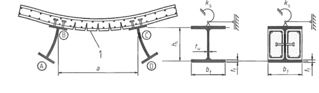
(1) The effects of the behaviour of the joints on the distribution of internal forces and 1110ments within a structure, and on the overall deformations of the structure, nlay generally be neglected, but where such effects are significant (such as in the case of semi-continuous joints) they should be taken into account, see Section 8 and EN 1993-1-8.
(2) To identify whether the effects of joint behaviour on the analysis need be into account, a distinction may be Inade between three joint l110dels as follows, see 8.2 and EN 1993-1-8,5.1.1:
simple, in which the joint nlay be assunled not to transmit bending moments;
continuous, in which the stiffness and/or resistance of the joint allow full continuity of the menlbers to be assuilled in the analysis;
senli-continuous, in which the behaviour of the joint needs to be taken into account in the analysis.
(3) For buildings, the requirenlents of the various types of joint are given in Section 8 and in EN 1993-1-8.
5.1.3 Ground-structure interaction
(l)P Account shall be taken of the defonnation characteristics of the supports where significant.
5.2 Structural stability
5.2.1 Effects of deformed geometry of the structure
(l) The action effects may generally be deternlined using either: - first-order analysis, using the initial geonletry of the structure
- second-order analysis, taking into account the influence of the defonnation of the structure.
(2)P effects of the defornled geonletry (second-order effects) shall be considered if they increase the action effects significantly or nl0dify significantly the structural behaviour.
(3) First-order analysis may be used if the increase of the relevant internal forces or n10ments caused by the deformations by first-order analysis is less than 100/0. This condition lllay be assuilled to be fulfilled if the following criterion is satisfied:
acr ~ 10 where:
(5.1)
acr is the factor by which the design loading would have to be increased to cause elastic instability.
(4)P In detelmining the stiffness of the structure, appropriate allowances shall be 111ade for cracking and creep of concrete and for the behaviour of the joints.
5.2.2 Methods of analysis for buildings
(1) Beam-and-colunln type plane fraIlles lllay be checked for sway nlode failure with first-order analysis if the criterion (5.1) is satisfied for each storey. In these structures an ll1ay be calculated using the expression given in EN 1993-1-1, 5 1 (4), provided that the axial conlpression in the beams is not significant and appropriate allowances are nlade for cracking of concrete, see 5.4.2.3, creep of concrete, see 5.4.2.2 and for the behaviour of the joints, see 8.2 and EN 1993-1-8, 5.1.
(2) Second-order effects lllay be included indirectly by using a first-order analysis with appropriate amplification.
(3) If second-order effects in individual Inen1bers and relevant melnber imperfections are fully accounted for in the global analysis of the structure, individual stability checks for the nlelnbers are un-necessary.
(4) If second-order effects in individual menlbers or certain nlenlber imperfections (e.g. for flexural and/or lateral-torsional buckling) are not fully accounted for in the global analysis, the stability of individuallllelllbers should be checked for the effects not included in the global analysis.
(5) If the global analysis neglects lateral-torsional effects, the resistance of a composite beanl to lateral-torsional buckling 111ay be checked using 6.4.
(6) For composite COlUnll1S and cOlnposite cOlnpression members, flexural stability nlay be checked using one of the following methods:
(a) by global analysis in accordance with 5.2.2(3), 'with the resistance of cross-sections being verified in accordance \vith 6.7.3.6 or 6.7.3 or