The
Eur
o
p
e
an
Uni
o
n
I
n
or
de
r
t
o
pr
omot
e
publ
i
c
e
duc
a
t
i
on
a
nd
publ
i
c
s
a
f
e
t
y,
e
qua
l
j
us
t
i
c
e
f
or
a
l
l
,
a
be
t
t
e
r
i
nf
or
me
d
c
i
t
i
ze
nr
y,
t
he
r
ul
e
of
l
a
w,
wor
l
d
t
r
a
de
a
nd
wor
l
d
pe
a
c
e
,
t
hi
s
l
e
ga
l
doc
ume
nt
i
s
he
r
e
by
ma
de
a
va
i
l
a
bl
e
on
a
nonc
omme
r
c
i
a
l
ba
s
i
s
,
a
s
i
t
i
s
t
he
r
i
ght
of
a
l
l
huma
ns
t
o
know
a
nd
s
pe
a
k
t
he
l
a
ws
t
ha
t
gove
r
n
t
he
m.
≠
EDI
CT
OF
GOVERNMENT
±
EN 1993-1-1 (2005) (English): Eurocode 3: Design of steel
structures - Part 1-1: General rules and rules for buildings
[Authority: The European Union Per Regulation 305/2011,
NORME EUROPEENNE
EUROpAISCHE NORM
ICS 91.010.30; 91.080.10 May 2005 English version Supersedes ENV 1993-1-1: 1992 Incorporating Corrigenda February 2006 and March 2009Eurocode 3: Design of steel structures - Part 1-1: General rules
and rules for buildings
Eurocode 3: Calcul des structures en aeier - Partie 1-1: Regles gE'merales et regles pour les batiments
Eurocode 3: Bemessung und Konstruktion von Stahlbauten - TeiI1-1: Allgemeine Bemessungsregeln und Regeln fOr
den Hochbau
This European Standard was approved by CEN on 16 April 2004.
CEN members are bound to comply with the CEN/CENELEC Internal Regulations which stipulate the conditions for giving this European Standard the status of a national standard without any alteration. Up-to-date lists and bibliographical references concerning such national standards may be obtained on application to the Central Secretariat or to any CEN member.
This European Standard exists in three official versions (English, French, German). A version in any other language made by translation under the responsibility of a CEN member into its own language and notified to the Central Secretariat has the same status as the official versions.
CEN members are the national standards bodies of Austria, Belgium, Cyprus, Czech Republic, Denmark, Estonia, Finland, France, Germany, Greece, Hungary, Iceland, Ireland, Italy, Latvia, Lithuania, Luxembourg, Malta, Netherlands, Norway, Poland, Portugal, Slovakia, Slovenia, Spain, Sweden, Switzerland and United Kingdom.
ECROPEA)'! COMMITTEE FOR STANDARDIZATION COM CROPEEN D NORMALISATION EUROPAISCHES KOMIT E FeR '-.'ORMUNCi
Management Centre: rue de Stassart, 36 B-1050 Brussels
2005 CEN All rights of exploitation in any form and by any means reserved worldwide for CEN national Members.
EN 1993-1-1:2005 (E)
Contents
Page Ceneral ... 9 1.1 Scope ... ... 9 1.2 ... ... 10 1.3 ASSlll1'1IJlions ... ... 111.4 Distinction bet}veen principles and application rules ... 11
1.5 Terl1'7S and de./iniliol1s ... 11
1.6 ~vlnbols ... ... 12
1.7 Conventions/or member axes ... ... 20
2 Basis of design ... 22
2.1 Requirelnents ... 22
2.] .1 Basic requirenlents ... 22
2.1.2 Reliability management ... 22
2.1.3 Design working life, durability and robustness ... 22
2.2 Principles qf'limit state ... 23
2.3 Basic variables ... 23
2.3.1 Actions and environmental influences ... 23
2.3.2 Material and product prope11ies ... 23
2.4 Verification b.y the partialfactor lnethod ... 23
2.4.1 Design values of material properties ... 23
2.4.2 Design values of geometrical data ... 23
2.4.3 Design resistances ... 24
2.4.4 Verification of static equilibrium (EQU) ... 24
2.5 Design a.,'sisled testing ... ... 24
3 Materials ... 25 3.1 General ... ... 25 3.2 Structur(}! sleel ... ... 25 3.2.1 Material properties ... 25 3.2.2 Ductility requirelnents ... 25 3.2.3 Fracture ... 25 3.2.4 Through-thickness properties ... 27 3.2.5 Tolerances ... 28
3.2.6 Design values of material coefficients ... 28
3.3 Connecting clevices ... 28
3.3.1 Fasteners ... 28
3.3.2 Welding cOl1sun1ablcs ... 28
3.4 Other prefabricated products in buildings ... 28
4 Durability ... 28
5 Structural analysis ... 29
5.1 Structural modellingfor analysis ... 29
EN 1993-1-1:2005 (E)
5.1.2 Joint 1110delling ... 29
5.1.3 Ground-structure interaction ... 29
5.2 Global anal.vsis ... 30
5.2.1 Effects of deformed geometry of tbe structure ... 30
5.2.2 Structural stability of frames ... 31
5.3 Inlper(ection,I,' ... 32
5.3.1 Basis ... 32
5.3.2 Imperfections for global analysis of frames ... 33
5.3.3 Imperfection for analysis of bracing systems ... 36
5.3.4 Mel11ber inlperfections ... . 5.4 l'vfelhods of ana(vsis considering material non-/inearities ...
38
5.4.1 General ... 38
5.4.2 Elastic global analysis ... 39
5.4.3 Plastic global analysis ... 39
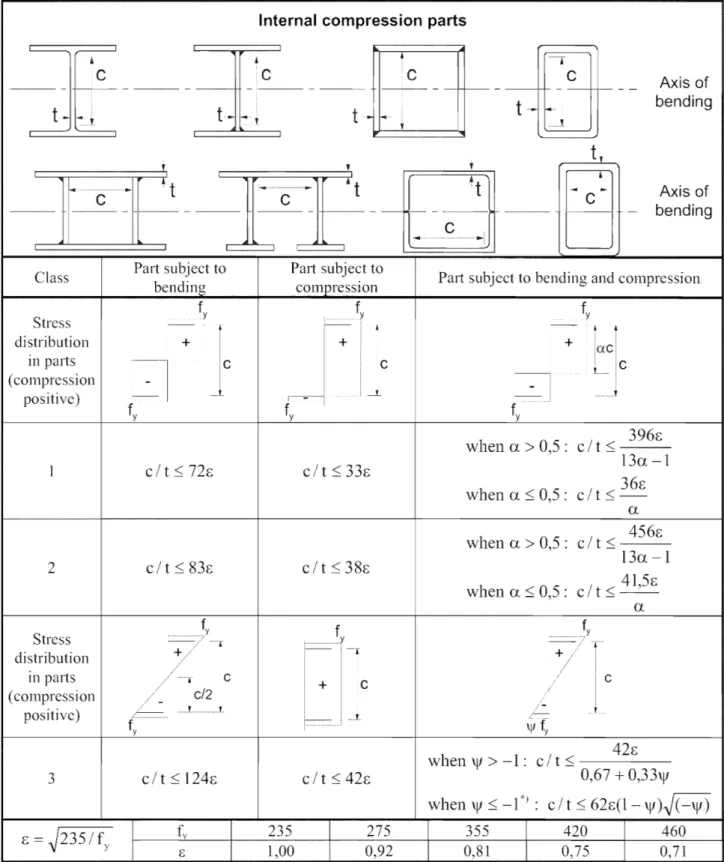
5.5 Classffication of cross sections ... ... 40
5.5.1 Basis ... 40
5.5.2 Classification ... 40
5.6 Cros.",'-,)'ection requirements for plastic global analysis ... 41
6 IJltilnate linlit states ... 45
6.1 General ... ... 45 6.2 Re.)'istance o.f·cross-sections ... 45 6.2.1 General ... 45 6.2.2 Sectioll properties ... 46 6.2.3 Tension ... 49 6.2.4 CO.nlpression ... 49 6.2.5 Bending nlonlent ... 50 6.2.6 Shear ... 50 6.2. 7 Torsion ... 52
6.2.8 Bending and shear ... 53
6.2.9 Bending and axial force ... 54
6.2.10 Bending, shear and axial force ... 56
6.3 Buckling resistance o./,l71el71bers ... 56
6.3.1 Uniform members in compression ... 56
6.3.2 Uniform members in bending ... 60
6.3.3 Uniform members in bending and axial compression ... 64
6.3.4 General method for lateral and lateral torsional buckling of structural components ... 65
6.3.5 Lateral torsional buckling of membcrs with plastic hinges ... 67
6.4 Untform built-lip compression members ... 69
6.4.1 General ... 69
6.4.2 Laced compression members ... 71
6.4.3 Battened compression members ... 72
6.4.4 Closely spaced built-up members ... 74
7 Serviceability limit states ... 75
7.1 General ... 75
7.2 Serviceabili(v limit statesfoJ' buildings ... 75
7.2.1 Vert.ical deflections ... 75
7.2.2 Horizontal deflections ... 75
7.2.3 Dynanlic effects ... 75
EN 1993-1-1:2005 (E)
Annex B [informative] - Method 2: Interaction factors kiJ for interaction formula in 6.3.3(4) ... 79 Annex AB [informative] - Additional design provisions ... 81 Annex BB [informative] - Buckling of components of building structures ... 82
Foreword
EN 1993-1-1:2005 (E)
This European Standard EN 1993, Eurocode 3: Design of steel structures, has been prepared by Technical Committee CEN/TC250 « Structural Eurocodes », the Secretariat of which is held by BSI. CEN/TC250 is responsible for all Structural Eurocodes.
This European Standard shall be given the status of a National Standard, either by publication of an identical text or by endorsement, at the latest by November 2005, and conflicting National Standards shall be withdrawn at latest by March 2010.
This Eurocode supersedes ENV 1993-1-1.
According to the CEN-CENELEC Internal Regulations, the National Standard Organizations of the following countries are bound to implement these European Standard: Austria, Belgium, Cyprus, Czech Republic, Denmark, Estonia, Finland, France, Germany, Greece, Hungary, Iceland, Ircland, Italy, Latvia, Lithuania, Luxembourg, Malta, Netherlands, Norway, Poland, Portugal, Slovakia, Slovenia, Spain, Swedcn, Switzerland and United Kingdom.
Background of the Eurocode programme
In 1975, the Commission of the European Community decided on an action programme 111 the field of construction, based on article 95 of the Treaty. The objective of the programme was the elimination of technical obstacles to trade and the harmonization of technical speci1~cations.
Within this action programme, the Commission took the initiative to establish a set of harmonized technical rules for the design of construction works which, in a first stage, would serve as an alternativc to the national rules in force in the Member States and, ultimately, would replace them.
For fifteen years, the Commission, with the help of a Stcering Committee with Representatives of Member States, conducted the development of the Eurocodes programme, which led to the first generation of European codes in the 1980s.
In 1989, the Commission and the Member States of the EU and EFTA decided, on the basis of an agreement I between the Commission and CEN, to transfer the preparation and the publication of the Eurocodes to the CEN through a series of Mandates, in order to provide them with a future status of European Standard (EN). This links de facto the Eurocodes with the provisions of all the Council's Directives and/or Commission's Decisions dealing with European standards (e.g. the Council Directive 89/1 06/EEC on construction products ~ CPD ~ and Council Directives 93/37/EEC, 92/50/EEC and 89/440/EEC on public works and services and equivalent EFTA Directives initiated in pursuit of setting up the internal market).
The Stluctural Eurocode programme comprises the following standards generally consisting of a number of Parts:
EN 1990 Eurocode: Basis of structural design EN 1991 Eurocode 1: Actions on structures
EN 1992 Eurocode 2: Design of concrete structures EN 1993 Eurocode 3: Design of steel stluctures
EN 1994 Eurocode 4: Design of composite steel and concrete structures EN 1995 Eurocode 5: Design of timber stluctures
EN 1996 Eurocode 6: Design of masonry structures EN ]997 Eurocode 7: Geotechnical design
EN 1998 Eurocode 8: Design of structures for earthquake resistance
I Agreement between the Commission of the European Communities and the European Committee for Standardisation (CEN) concerning the work on EUROCODES for the design of building and civil engineering works (Bc/CEN/03/89).
EN 1993-1-1:2005 (E)
EN ] 999 Eurocode 9: Design of aluminium structures
Eurocode standards recognize the responsibility of regulatory authorities in each Member State and have safeguarded their right to determine values related to regulatory safety matters at national level where these continue to vary from State to State.
Status and field of application of Eurocodes
The Member States of the EU and EFTA recognize that Eurocodes serve as reference documents for the fonowing purposes:
as a means to prove compliance of building and civil engineering works with the essential requirements of Council Directive 89/1 06/EEC, particularly Essential Requirement N° 1 - Mechanical resistance and stability - and Essential Requirement N°2 Safety in case of fire;
as a basis for specifying contracts for construction works and related engineering services;
as a framework for drawing up harmonized technical specifications for construction products (ENs and ETAs)
The Eurocodes, as far as they concern the construction works themselves, have a direct relationship with the Interpretative Documents2 referred to in Article 12 of the CPD, although they are of a different nature from harmonized product standard3. Therefore, technical aspects arising from the Eurocodes work need to be adequately considered by CEN Technical Committees and/or EOTA Working Groups working on product standards with a view to achieving a full compatibility of these technical specifications with the Eurocodes. The Eurocode standards provide common structural design rules for everyday use for the design of whole structures and component products of both a traditional and an innovative nature. Unusual forms of construction or design conditions are not specifically covercd and additional expert consideration will be required by the designer in such cases.
National Standards implementing Eurocodes
The National Standards implementing Eurocodes will comprise the full text of the Eurocode (including any annexes), as published by which may be preceded by a National title page and National foreword, and may be followed by a National annex (informative).
The National Annex (informative) may only contain information on those parameters which are left open in the Eurocode for national choice, known as Nationally Determined Parameters, to be used for the design of buildings and civil engineering works to be constructed in the country concerned, i.e. :
values for partial factors and/or classes whcre alternatives are given in the Eurocode, values to be used where a symbol only is given in the Eurocode~
geographical and climatic data specific to the Member State, e.g. snow map, the procedure to be used where alternative procedures are given in the Eurocode,
references to non-contradictory complementary information to assist the user to apply the Eurocode.
Links between Eurocodes and product harmonized technical specifications (ENs
('"".-rill-'" to Art. 3 _3 of the CPD, the essential requirements (ERs) shall be concrete form in interpretative documents for the creation of tile necessary Jinks betwcen the essential requirements and the mandates tor hENs and ETAGsiETAs.
According to Art. 12 of the CPD the interpretative documents shall :
a) concrete form to the essential harmonizing the t"'·",,,,,,,I,,,n( and the technical bases and indicating classes where necessary;
b) these classes or levels of requirement with the technical e.g. methods of calculation and technical rules for design. etc. ;
c) serve as a reference for the establishment standards and guidelines for European technical approvals. The Eurocodes, de playa similar role in the field of the ER 1 and a part ofER 2.
and ETAs)
EN
1993-1-1:2005 (E)
There is a need for consistency between the harmonized technical specifications for construction products and the technical rulcs for works4. Furthermore, all the information accompanying thc CE Marking of the constIuction products which rcfcr to Eurocodes should clearly mention which Nationally Determined ParaIneters have been taken into account.
Additional information specific to EN 1993-1
EN 1993 is intended to be used with Eurocodes EN 1990 - Basis of Structural Design, EN 1991 - Actions on structures and EN 1992 to EN 1999, when steel stluctures or steel components are rcferred to.
EN 1993-1 is the first of six parts of EN 1993 Design of Steel Structures. It gives generic design rules intended to be used with the other parts EN 1993-2 to EN 1993-6. It also gives supplementary rules applicable only to buildings.
EN 1993-1 comprises twelve subparts EN 1993-1-1 to EN 1993-1-12 each addressing specific stcel components, lilnit states or materials.
It may also be used for design cases not covered by the Eurocodes (other structures, other actions, othcr materials) serving as a reference document for other CEN TC's concenling structural matters.
EN 1993-1 is intended for use by
committees drafting design related product, tcsting and execution standards, clients (e.g. for the formulation of their specific requirements)
designers and constructors relevant authorities
Numerical values for patiial factors and other reliability parameters are recommended as basic values that provide an acceptable level of reliability. They have been selected assuming that an appropriate level of worlananship and quality management applies.
EN 1993-1-1:2005 (E)
National annex for EN 1993-1-1
This standard gives values with notes indicating where national choices may have to be made. Therefore the National Standard implementing EN 1993-1 should have a National Annex containing all Nationally Determined Parameters to be used for the design ~ of steel structures and civil engineering works to be constructed @2] in the relevant country.
National choice is allowed in EN 1993-1-1 through the following clauses: 2.3.1(1) 3.1(2) 3.2.1 (I) 3.2.2( I) 3.2.3(1) 3.2.3(3)8 3.2.4(1 )8 5.2.1(3) 5.2.2(8) 5.3.2(3) 5.3.2(11 ) 5.3.4(3) 6.1(1) 6.1(1)B 6.3.2.2(2) 6.3.2.3(1) 6.3.2.3(2) 6.3.2.4(1)8 6.3.2.4(2)8 6.3.3(5) 6.3.4(1) 7.2.1(1)B 7.2.2(1)B 7.2.3(1 )8 BB.1.3(3)B
EN 1993-1-1:2005 (E)
1
General
1.1
Scope
1.1.1 Scope of Eurocode 3
(1) Eurocodc 3 applies to the design of buildings and civil engineering works in steel. It complies with the principles and requirements for the safety and serviceability of structures, the basis of their design and verification that are given in EN 1990 Basis of structural design.
(2) Eurocode 3 is concerned only \vith requirements for resistance, serviceability, durability and fire resistance of steel structures. Other requirements, e.g. concerning thermal or sound insulation, are not covered.
(3) Euroeode 3 is intended to be used in conjunction with: EN 1990 "Basis of structural design"
EN 1991 '"Actions on structures"
ENs, ET AGs and ETAs for construction products relevant for steel structures EN 1090 "Execution of Steel Structures - Technical requirements"
EN 1992 to EN 1999 when steel structures or steel components are referred to (4) Eurocode 3 is subdivided in various parts:
EN 1993-1 Design of Steel Structures: General rules and rules for buildings. EN 1993-2 Design of Steel Structures: Steel bridges.
EN 1993-3 Design of Steel Structures: Towers, masts and chimneys. EN 1993-4 Design of Steel Structures: Silos, tanks and pipelines. EN 1993-5 Design of Steel Structures: Piling.
EN 1993-6 Design of Steel Structures: Crane supporting structures.
(5) EN 1993-2 to EN 1993-6 refer to the generic rules
in
EN 1993-1. The rules in parts EN 1993-2 to EN 1993-6 supplement the generic lules in EN 1993-1.(6) EN 1993-1 "General rules and lules for buildings" comprises:
EN ] 993-1-1 Design of Steel Structures: General rules and rules for buildings. EN 1993-1-2 Design of Steel Structures: Structural fire design.
EN 1993-1-3 Design of Steel Struchlres:
I
AC 2) Cold-formed members and sheeting@l].
EN 1993-1-4 Design of Steel Structures: Stainless steels.
Design of Steel Structures: Plated structural elements.
Design of Steel Structures: Strength and stability of shell structures. EN 1993-1-5
EN 1993-1-6
EN 1993-1-7 Design of Steel Stluctures : Strength and stability of planar plated structures transversely loaded.
EN 1993-1-8 EN 1993-1-9
Design of Steel Stluetures : Design of joints.
Design of Steel Structures: Fatigue strength of steel structures.
EN 1993-1-10 Design of Steel StIuctufes : Selection of steel for fracture toughness and through-thickness properties.
EN 1993-1-11 Design of Steel Structures: Design of structures \vith tension components made of steel. EN 1993-1-12 Design of Steel Structures: Supplementary rules for high strength steel.
EN 1993-1-1:2005 (E)
1.1.2 Scope of Part 1.1 of Eurocode 3
(1) EN 1993-1-1 basic design rules for stccl structurcs with material thicknesses t 2: 3 mm. It also gives supplementary provisions for the structural design of steel buildings. These supplementary provisions are indicated by the lettcr "B" after thc paragraph number, thus ( )B.
NOTE ~Forcold formed members and sheeting, see EN 1993-1-3 @lI. (2) The following subjects are dealt with in EN 1993-1-1:
Section
1:
General Section 2: Basis of Section 3: Materials Section 4: DurabilitySection 5: Structural analysis Section 6: Ultimate limit states Section 7: Scrviceability limit states
(3) Sections 1 to 2 provide additional clauses to those given in EN 1990 "Basis of structural design". (4) Section 3 deals with matcrial properties of products made of low alloy structural steels.
(5) Section 4 general ru1cs for durability.
(6) Section 5 refers to the structural analysis of structures, in which tile melnbers can be modelled with sufficient accuracy as line e1cments for global analysis.
(7) Section 6 gives detailed rules for thc design of cross sections and members. (8) Section 7 gives rules for serviceability.
1.2 Normative references
This European Standard incorporates by dated or undated reference, provisions from other publica60ns. These normative references are cited at the appropriate places in the text and the publications are listed hereafter. For dated references, subsequent amendmcnts to or revisions of any of publications apply to this Europcan Standard only when incorporated in it by amendment or revision. For undated references the latest edition of the publication referred to applics (including amendillents).
1.2.1 General reference standards
EN 1090 Execution of steel structurcs - Technical requirements
EN ISO 12944 Paints and varnishes Corrosion protection of steel structures by protective paint
EN ISO] 461 @lI Hot dip galvanized coatings on fabricated iron and steel articles - specifications and test methods
1.2.2 Weldable structural steel reference standards
EN 10025-1 :2004 Hot-rolled products of stIllctural steels - Pmi 1: General delivelY conditions.
EN 10025-2:2004 Hot-rolled products of structural steels - Part 2: Technical delivery conditions for n011-alloy structural
EN 10025-3:2004 Hot-rolled products of stlllctural steels - Part 3: Technical delivery conditions for normalized / normalized rolled weldable fine grain structural steels.
EN 1993-1-1:2005 (E)
EN 10025-4:2004 Hot-rolled products of structural Part 4: Technical dclivery conditions for thermomechanical rolled weldable finc grain structural steels.
EN 10025-5:2004 Hot-rolled products of structural steels - Part 5: Technical delivery conditions for structural steels with improved atmospheric corrosion resistance.
EN 10025-6:2004 Hot-rolled products of structural steels - Part 6: Technical delivery conditions for l1at products of high yield strcngth structural steels in the quenched and tempered condition. EN 10164: 1993 Stcel products with improved deformation propel1ies perpendicular to the surface of thc
product - Technical delivery conditions.
EN 10210-1: 1994 Hot finished structural hollow sections of nonalloy and fine grain structural steels -Part 1: Technical delivcry requircmcnts.
EN 10219-1: 1997 Cold formed hollow sections of structural stcel - Part 1: Technical delivery requirements.
1.3 Assumptions
(1) In addition to the assumptions of EN 1990 the following assumptions apply: fabrication and erection complies with EN 1090
1.4 Distinction between principles and application rules
(1) The rules in EN 1990 clause 1.4 apply.
1.5 Terms and definitions
(1) The rules
in
EN 1990 clause 1.5 apply.(2) The following terms and definitions are used in EN 1993-1-1 with the following meanings:
1.5.1 frame
the whole or a portion of a structure, comprising an assembly of directly connected structural elements, designed to act together to resist load; this term refers to both moment-resisting frames and triangulated .LL<.4.LLL,",,>, it covers both plane frames and three-dimensional frames
1.5.2 sub-frame
a frame that fonns part of a larger frame, but is be treated as an isolated frame in a structural analysis
1.5.3
type of framing
terms used to distinguish between frames that are either:
semi-continuous, in which the structural properties of the members and joints need explicit consideration in the global analysis
continuous, in which only the structural propeliies of the members need be considered in the global analysis
shnple, in which the joints are not required to resist moments
1.5.4
global anaJysis
the detennination of a consistent set of internal forces and moments in a structure, which arc in equilibrium with a particular set of actions on the structure
EN 1993-1-1:2005 (E)
1.5.5
system length
distance in a given plane between two adjacent points at which a nlember is braced against lateral displacement in this plane, or between one such point and the end of the member
1.5.6
buckling Jength
system length of an otherwise similar member with pinned ends, which has the Saine critical buckling load as a given mcmber or segment of nlcmber
1.5.7
shear lag effect
non-uniform stress distribution in wide flanges due to shear deformation; it is taken into account by using a reduced "effecti ve" flange width in safety assessments
1.5.8
capacity design
design method for achieving the plastic deformation capacity of a Inember by providing additional strength in its connections and in other parts connected to it
1.5.9
uniform member
member with a constant cross-section along its whole length
1.6 Symbols
(1) For the purpose of this standard the following symbols apply. (2) Additional symbols are defined wherc they first occur.
NOTE Symbols are ordered by appearance in EN 1993-1-1. Symbols may have various meanings. Section /
x-x axis along a member y-y axis of a cross-section z-z axis of a cross-section
u-u major principal axis (where this does not coincide with the y-y axis) v-v minor principal axis (where this docs not coincide with the z-z axis) b width of a cross section
h depth of a cross section
d depth of straight pOliion of a web tw web thickness
tr flangc thickness r radius of root fillet
fl radius of root fillct
1'2 toe radius thickness Section 2
EN 1993-1-1:2005 (E)
~ Xk @.il characteri stic values of material propertyXn nonlinal values of material property Rd design value of resistance
Rk characteristic value of resistance YM genera] partial factor
YMi particular partial factor YMf partial factor for fatigue 11 conversion factor
ad design value of geometrical data Section 3
fy yield strength fu ultimate strength
[§)
ReH (Aczl yield strength to product standardsRm ultimate strength to product standards Ao original cross-section area
Cy yield strain CLi u ltill1ate strai n
required design Z-value resulting frOll1 the magnitude of strains from restrained metal shrinkage under the weld beads.
ZRd available design Z-value E modulus of elasticity G shear modulus
v Poisson's ratio in elastic stage
U coefficient of linear thermal expansion Section 5
Ucr factor by which the design loads would have to be increased to cause elastic instability in a global mode
FEd design loading on the structure
Fer elastic critical buckling load for global instability mode based on initial elastic stiffnesses
[§)
total design horizontal load, including equivalent forces transferred by the storey (storey shear)@lI
[§)
V Ed total design vertical load on the frame transferred by the storey (storey thlust)@lI
bH,Ed horizontal displacement at the top of the storey, relative to the bottom of the storey h storey height
A
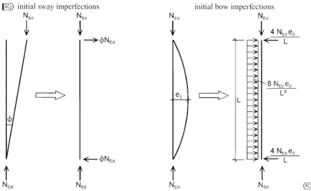
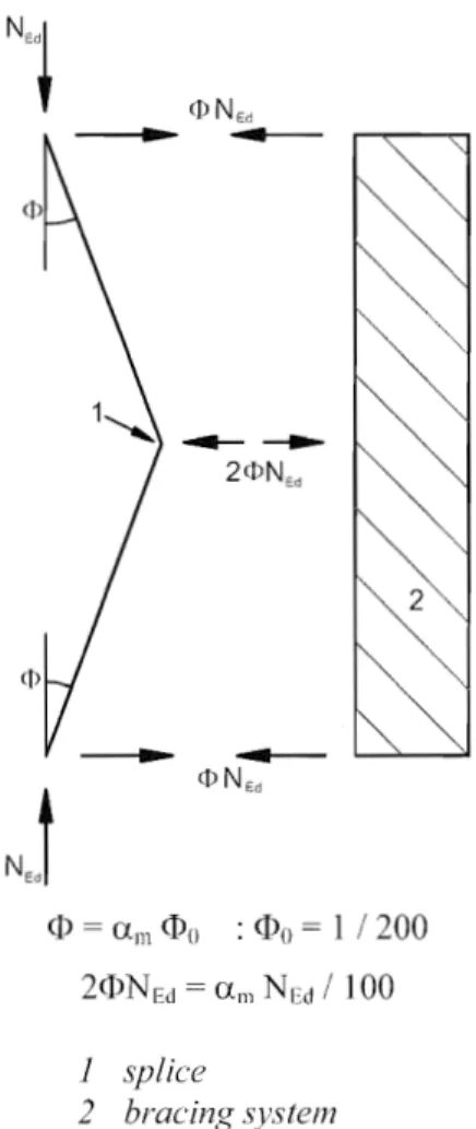
non dimensional slende111ess NEd design value of the axial force <P global initial sway imperfection<Po basic value for global initial sway imperfection Uh reduction factor for height h applicable to columns h height of the structure
EN 1993-1-1:2005 (E)
am reduction factor for the number of columns in a row m number of columns in a row
eo maximum amplitude of a member imperfection L member length
Tjinit amplitude of clastic critical buckling mode
11cr shape of clastic critical buckling mode
eO.d design value of maximum amplitude of an imperfection MRk characteristic momcnt resistance of the critical cross section
characteristic resistance to normal force of the critical cross section a imperfection factor
Ell1~r bending moment due tOller at the critical cross section X reduction factor for the relevant buckling curve
aull.k minimum load amplifier of the design loads to reach the characteristic resistance of the most critical
cross section of thc structural component considering its in plane behaviour without taking lateral or lateral torsional buckling into account however accounting for all effects due to in plane geometrical deformation and imperfections, global and local, whcrc relevant ~
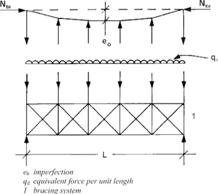
acr minimum force amplifier to reach the ~ elastic critical buckling load ~ q equivalent force per unit
8q in-plane deflection of a bracing systen1
qel equivalent design force per unit length MEd design bending moment
k factor for eO.d E strain
(J strcss
(j"com,Ed maximum design compressive stress in an element
e
c ad
length factor depending on fy ~width or depth of a part of a cross section
portion of a paI1 of a cross section in compression stress or strain ratio
plate buckling factor ~
outer diameter of circular tubular sections Section 6
YMO partial factor for resistance of cross-sections whatever the class is
YMI pal1ial factor for resistance of members to instability assessed by member checks YM2 partial factor for resistance of cross-sections in tension to fracture
ax.Ed design value of the local longitudinal stress (Jz.Ed design value of the local transverse stress 'TEd design value of the local shear stress
N Ed design norma] force
M y.Ed design bending moment, y-y axis
EN 1993-1-1:2005 (E)
My,Rd design values of the resistancc to bending moments, y-yMz,Rd design values of the resistance to bending moments, z-z axis
s staggered pitch, the spacing of the centrcs of 1\-\10 consecutive holes in the chain measured parallel to the nlember axis
p spaeing of the centres of the same two holes measured perpendicular to the member axis
n number of holes extending in any diagonal or L . I " ' - -LUl"'- line progressively across the member or part of the member
do diameter of hole
eN shift of the centroid of the effective area AelT relative to the centre of gravity of the gross cross section L1MEd additional moment from shift of the centroid of the effective area
of the gross cross scction
relative to the centre of gravity
AetT effectivc area of a cross section
N tRd design valucs of the resistance to tension forces
design plastic resistancc to normal forces of the gross cross-section
Nu,Rd design ultimate resistance to normal forces of the net cross-section at holes for fasteners
Allet net area of a cross section
Nnet,RcI design plastic resistance to normal forces of the net cross-section
Nc,Rd design resistance to normal forces of the cross-section for uniform compression Mc,Rd design resistance for bcnding about one principal axis of a cross-section W pl plastic section modulus
W e1,min Ininin1um elastic section modulus
Weff.min minimum effective section modulus Af area of the tension flange
Af,net net area of the tension flange V Ed design shear force
Vc,Rd design shear resistance l6§) V pl,Rd design plastic shear resistance
Av shear area
11 factor for shear area S first moment of area
second moment of area A cross-sectional area Aw area of a web Af area of one flange
T Ed design value of total torsional moments T Rd design resistance to torsional moments
l6§) Tt,Ed design value of internal St. Vcnant torsional moment
@II
I
AC2) Tw, Ed design value of internal warping torsional moment@II
't'tEd design shear stresses due to S1. Venant torsion Tw,Ed design shear stresses due to warping torsion C'w.Ed design direct stresses due to the bimoment BEd BEd design value of the bimoment
@II
EN 1993-1-1:2005 (E)
p reduction factor to determine reduced design values of the resistance to bending moments making allowance for the presence of shear forces
MV"Rd reduced design values of thc resistance to bending moments making allowance for the presence of shear forces
M
N .. Rd reduced design values of the resistance to bending moments making allowance for the presence of normal forcesn ratio of design normal force to design plastic resistance to normal forces of the gross cross-section a ratio of web area to gross area
ex parameter introducing the effect of biaxial bending
p
parameter introducing the cffect of biaxial bendingeny shift of the ccntroid of the effective area relative to the centre of gravity of the gross cross section (y-y
eN] sh ift of the centroid of the effective area AelT relative to the centre of gravity of the gross cross section axis)
minimum cffcctive section modulus
Nb,Rd design buckling resistance of a compression member X reduction factor for relevant buckling mode
(I) va1ue to determine the rcduction factor X
ao, a, b, c, d class indexes for buckling curves
Ncr elastic critical force for the relevant buckling mode based on the gross cross sectional properties radius of gyration about the relevant axis, determined using the prope11ies of the gross cross-section AI slenderness value to determine the relative slendemcss
)'" T relative slenderness for torsional or torsional-flexural buckling Ncr.TF elastic torsional-l1exura I buckling force
elastic torsional buckling force Mb,Rd design buckling resistance lTI0l11ent
XLT
reduction factor for lateral-torsional buckling<DLT
value to determine the reduction factorXLT
ex LT imperfection factor
A LT non dimensional slenderness for lateral torsional buckling
Mer
elastic critical moment for lateral-torsional bucklingI'A plateau length of the lateral torsional buckling curves ~ for rolled and welded sections @l]
p
correction factor for the lateral torsional buckling curves ~ for rolled and welded sections @l]XLT.mod modified reduction factor for lateral-torsional buckling f modification factor for
XLT
kc
correction factor for moment distribution~J ratio of moments in segment
Lc
length between latera1 rcstraintsAI'
equivalent compression slendernessradius of gyration of compression flange about the minor axis of the section
effective area of compression tlange AetT,w,ceffective area of compressed part of web
Aco slenderness parameter k fi modification flictor
moments due to the shift of the centroidal y-y axis
~ ilMz.Ed @l) moments due to the shift of the centroidal z-z axis
Xy
reduction factor due to tlexural buckling (y-y axis)XZ
reduction factor due to tlexural buckling axis) kyy interaction factorkyz interaction factor kzy interaction factor kzz interaction factor
EN 1993-1-1:2005 (E)
Aop global non dimensional slenderness of a structural component for out-of-plane buckling Xop reduction factor for the non-dimensional slenderness Aop
Uult.k minimum load amplifier of the design loads to reach the characteristic resistance of the most critical cross section
ucr,op minimum amplifier for the in plane loads to reach the elastic ~critical buckling load ~ with to lateral or lateral torsional buckling
NRk characteristic value of rcsistance to compression
My,Rk characteristic value of resistance to bending moments about y-y axis Mz.Rk characteristic value of resistance to bending moments about z-z axis
Qm
local force applied at each stabilized member at the plastic hinge locationsstable length of segment buckling length of chord
ho distance of centrelines of chords of a built-up column a distance between restraints of chords
U angle between axes of chord and lacings 1m in minimum radius of gyration of single ACh area of one chord of a built-up column
design chord force in the middle of a built-up lTIember
M
~d design value of the L60maximum first order moment@l]
in the middle of the built-up memberletT effective second moment of area of the built-up member
shear stiffness of built-up member from the lacings or battened panel n number of planes of lacings or battens
Ad area of one diagonal of a built-up column d length of a diagonal of a built-up column
Av area of one post (or transverse element) of a built-up column Ich in plane second moment of area of a chord
Ib in plane second moment of area of a batten
EN 1993-1-1:2005 (E)
1) radius of gyration (y-y axis)Annex A
Cmy equivalent uniform moment factor
Cm? equivalent uniform moment factor
equivalent uniform moment factor factor
PI factor
elastic i1exural buckling force about the y-y axis Ncr,? clastic flexural buckling force about the z-z axis
factor Cyz factor f~lctor Czz factor factor Wz tactor IlpJ factor
Amax
maximum ofAy
and j",zbLT factor
Cn factor d n factor eLI' factor
\/fy ratio of end moments (y-y axis) Cmy,() factor
Cmz.O factor an factor
h
St. Venant torsional constantIy
second moment of area about y-y axis~ C1 ratio between the critical bending moment (largest value along the member) and the critical constant
bending moment for a member with hinged supports @1] Mi,Ed(X) maximum first order moment
maximum member displacement along the melnber
Annex B
I
AC 2) as factor; s = saggingI
AC 2) ah factor; h hogging @1]ell
equivalent uniform moment factor Annex ABYG pal1ial factor for permanent loads Gk characteristic value of permanent loads
Annex BB
AefLv effective slenderness ratio for buckling about v-v axis
.y effective slcndcI11ess ratio for buckling about y-y axis
effective slenderness ratio for buckling about z-z axis L system length
Lcr buckling length
S shear stiffness providcd by sheeting
Iw
warping constantCS,k rotational stiffness providcd by stabilizing continuum and conncctions
Ku
factor for considering the type of analysisfactor for considering the moment distribution and the type of restraint
EN 1993-1-1:2005 (E)
rotational stiffness provided thc stabilizing continuum to the beam assuming a stiff connection to the member
rotational stiffness of the connection between the beam and the stabilizing continuum
CSD.k rotational stiffness deduced from an analysis of the distorsional deformations of the beam cross
sections
Lm
stable length between adjacent lateral restraints Lk stable length between adjaccnt torsional restraintsstable length between a plastic hinge location and an adjacent torsional restraint C1 modification factor for moment distribution
modification factor for linear moment gradient Cn modification factor for non-linear moment gradicnt
a distance between the ccntroid of the member with the plastic hinge and the centroid of the restraint members
Bo
factor BI factorB2
factor~ 11 ratio of clastic critical values of axial forces
Is radius of gyration related to centroid of restraining men1ber
~L ratio of the algebraically smaller end moment to the larger end moment
R\
moment at a specific location of a memberR2
mOll1ent at a specific location of a memberR3
moment at a specific location of a member~ moment at a specific location of a member
R5
mOll1ent at a specific location of a memberRE
maximum ofRI
orR5
Rs
Inaximum value of bending moment anywhere in the length c taper factorhh additional depth of the haunch or taper
hmax maximum depth of cross-section within thc length
Ly
EN 1993-1-1:2005 (E)
hs vertical depth of the un-hallnched section
Lh length of haunch within the length Ly length between restraints
1.7 Conventions for member axes
(1) The convention for member axes is: x-x - along the member
y-y - axis of the cross-section z-z - axis of the cross-section
(2) For steel members, the cOllventions used for cross-section axes are: - generally:
y-y - cross-section axis parallel to the f1anges z-z - cross-section axis perpendicular to the flanges - for angle sections:
y-y axis parallel to the smaller leg z-z - axis perpendicular to the smaller leg where necessary:
ll-ll - major principal axis (where this does not coincide with the yy axis) v-v - minor principal axis (where this does not coincide with the zz axis)
(3) The symbols used for dimensions and axes of rolled steel sections are indicated in Figure 1.1.
(4) The convention used for subscripts that indicate axes for 1110ments is: "Use the axis about which the moment acts."
NOTE All rules in this Eurocode relate to principal axis properties, which are generally defined by the axes y-y and z-z but for sections such as angles are defined by the axes u-u and v-v.
d
z
I~
Y
I-y
.,
i~t
z "
I/
b/4
z
z
b
~
/ / .-/ Zh
zh
d
y
I Zz
z
b/2
b
EN
1993-1-1:2005
(E)
z
t
VI
Figure 1.1: Dimensions and axes of sections
EN 1993-1-1:2005 (E)
2 Basis of design
2.1
Requirements
2.1.1 Basic requirements
IEJ) (l)P The design of steel structures shall be in accordance with the rules in EN 1990. @j]
(2) The supplementary provisions for steel structures given in this section should also be applied.
(3) The basic requirements oLEN 1990 section 2 should be deemed be satisfied where limit state design is lIsed in conjunction with the pm1ial factor method and the load combinations given in EN 1990 together with the actions given in EN 1991.
(4) The rules for resistances, serviceabi lity and durability given in the various pm1s of EN ] 993 should be applied.
2.1.2 Reliability management
(I) Where different levels of reliability are required, these levels should preferably be achieved by an appropriate choice of quality managcment in design and execution, according to EN 1990 Annex C and EN 1090.
2.1.3 Design working life, durability and robustness
2.1.3.1
Genera]
(l)P Depending upon the type of action affecting durability and the design working life (see EN 1990) steel structures shall be @j]
designed against corrosion by means of
suitable surface protection (see EN ISO 12944) the use of \vcathering steel
the usc of stainlcss stccl EN 1993-1-4) detailed for sufficient fatiguc life
designed for wearing
EN 1993-1-9)
designed for accidental actions (see EN 1991 inspected and maintained.
2.1.3.2
Design working Bfe for buildings
IEJ) (l)P,B The design working life shall be taken as the period for which a building structure is expected to be used for its intendcd purpose.
(2)B For the specification of the intended design working life of a permanent building sec Table 2.1 of EN 1990.
(3)8 For structural elements that cannot be designed for the total design life of the building, see 2.1.3.3(3)B.
2.1.3.3
Durability for buildings
~ (1 )P,B To ensure durability, buildings and their components shall either be designed for environmental actions and if relevant or else protected from them.
EN 1993-1-1:2005 (E)
~ (2)P,B The effects of deterioration of material, corrosion or fatigue where relevant shall bc takcn into account by appropriate choice of material, see EN 1993-1-4 and EN 1993-1-10, and dctails, sce EN 1993-1-9, or by structural redundancy and by the choicc of an appropriate corrosion protection system. (3)8
If
a building includes components that need to be replaceable (e.g. bearings in zones of soil scttlemcnt), thc possibility of their safc rcplacemcnt should bc verified as a transient design situation.2.2 Principles of limit state design
(1) The resistance of cross-sections and members specificd in this Eurocodc 3 for the ultimate limit states as defined ~ in the clause 3.3 1990 arc based on tests in which the material exhibited sufficient ductility to apply simplified
(2) The resistances specified in this Eurocode Part may therefore be used where the conditions for Inaterials in section 3 are met.
2.3 Basic variables
2.3.1 Actions and environmental influences
(l) Actions for the design of steel structures should be taken from EN 1991. For the combination of actions and partial factors of actions see Annex A to EN 1990.
NOTE 1 The National Annex may define actions for particular regional or climatic or accidental situations.
NOTE 2B For proportional loading for incremental approach, see Annex AB.l. NOTE 3B For simplified load arrangement, see Annex AB.2.
(2) The actions to be considered in the erection should be obtained from EN 1991-1-6.
(3) Where the effects of predicted absolute and differential settlements need to be considered, best estimates of imposed deformations should be used.
(4) The effects of uneven settlements or irnposed deformations or other forms of imposed during erection should be taken into account by their nominal value Pk as permanent actions and grouped
with other permanent actions Gk to form a single action @.il (Gk
+
Pd.
(5) Fatigue actions not defined in EN 1991 should be determined """r>A"","rr to Annex A of EN 1993-1-9. 2.3.2 Material and product properties
(l) Material properties for steels and other construction products and the geometrical data to be used for design should be those specified in the relevant ET AGs or ETAs unless otherwise indicated in this standard.
2.4 Verification by the partial factor method
2.4.1 Design values of material properties
~ (1) P For the of steel structures characteristic values or nominal values Xll of material properties shall be used as indicated in this Eurocode. @.il
2.4.2 Design values of geometrical data
(1) Geometrical data for cross-sections and systems may be taken from product standards hEN or drawings for the execution to EN 1090 and treated as nominal values.
EN 1993-1-1:2005 (E)
(2) Design values of geometrical imperfections specified in this standard are equivalent geometric imperfections that take into account the effects of:
geometrical imperfections of members as gove111ed by geometrical tolerances in product standards or the execution standard;
structural imperfections due to fabrication and erection; residual stresses;
variation of the yield strength.
2.4.3 Design resistances
(]) For steel structures equation (6.6c) or equation (6.6d) of EN 1990 applies:
~
Rk
]
(
..
. )
~ Rd - Rk 1ll
X
k.I'lli X
kj, adYM
1M
(2.1)
where Rk is the characteristic value of the particu lar resistance determined with characteristic or nominal values for the material properties and dimensions
YM is the global partial factor for the particular resistance
NOTE For the definitions Ofl11, lli' Xkl , Xki and ad see EN 1990.
2.4.4 Verification of static equilibrium (EQU)
(1) The reI iability format for the verification of static equilibrium in Table 1.2 (A) in Annex A of EN 1990 also applies to design situations equivalent to (EQU), e.g. for the design of holding down anchors or the verification of uplift of bearings of continuous beams.
2.5 Design assisted by testing
(l) The resistances Rk in this standard have been determined using Annex D of EN 1990.
(2) In recommending classes of constant partial factors YMi the characteristic values Rk were obtained from (2.2) where Rei are design values according to Annex D of EN 1990
YMi are recommended partial factors.
NOTE 1 The numerical values of the recommended partial factors YMi have been detennined such that Rk represents approximately the 5 %-fractile for an infinite nUlYlber of tests.
NOTE 2 For characteristic values of fatigue strength and pa11ial factorsYMf for fatigue see EN 1993-1-9.
NOTE 3 For characteristic values of toughness resistance and safety elements for the toughness verification see EN 1993-1-] O.
(3) Where resistances Rk for prefabricated products should be determined from tests, the procedure in (2) should be followed.
3 Materials
3.1 General
EN 1993-1-1:2005 (E)
(1) The nominal values of material properties given in this section should be adopted as characteristic values in design calculations.
(2) This Part of EN 1993 covers the design of steel structures fabricated from steel material conforming to the steel grades listed in Table 3.1.
NOTE For other steel material and products see National Annex.
3.2 Structural steel
3.2.1
Material properties
(1) The nominal values of the yield strength fy and the ultimate strength £:1 for structural stccl should bc obtained
a) either by adopting the valucs ~ fy = ReH and t~J = Rm direct from the product standard b) or by using the simplification givcn in Tablc 3.1
NOTE The National Annex may the choice.
3.2.2
Ductility requirements
(1) For steels a minimum ductility is required that should be expressed in terms of limits for:
the ratio t~ I fy of the specified minimum ultimate tensile strength
fu
to the specified minimum yield strength .the elongation at failure on a gauge length of 5,65 (where Ao is the original cross-sectional area); the ultimate strain Eu, where Eu corresponds to the ultimate strength £:J .
NOTE The limiting values of the ratio fll I fy , the elongation at failure and the ultimate strain Cli may be defined
in
the National Annex. The following values are recommended:fu
I fy 1,10;elongation at failure not less than 15%; ClI 15Ey , where Cy is the yield strain (Cy fy I
(2) Steel conforming with one of the steel grades listed in Table 3.1 should be accepted as satisfying these requ irements.
3.2.3
Fracture toughness
(l)P The material shall have sufficient fracture toughness to avoid brittle fracture of tension clements at the lowest servicc temperature expected to occur within the intended design life of the structurc. @il
NOTE The lowest service temperature to be adopted in design may be given in the National Annex. (2) No further check against brittle fracture need to be made if the conditions in EN 1993
-1
-10 are satisfied for the lowest temperature.EN 1993-1-1:2005 (E)
(3)B For building components under compression a minimum toughness property should be selected.
NOTE B The National Annex may give information on the selection of toughness properties for members in compression. The use of Table 2.1 of EN 1993-1-10 for 0Ed = 0,25 fY(t) is recommended.
(4) For selecting steels for members with hot dip galvanized coatings see I£§) EN ISO 1461 @l].
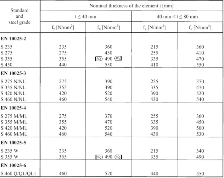
Table 3.1: Nominal values of yield strength fy and ultimate tensile strength fu for
hot rolled structural steel
Standard
Nominal thickness of the element t [111m]
and t 40mm 40 111m < t :::: 80 mm stccl t~
[N/mm2]
fu
[N/mm2] f~,[N/mm2]
t~ [N/mnl] EN 10025-2 S 235 235 360 215 360 S 275 275 430 255 410 S 355 355 490 335 470 S 450 440 550 410 550 EN 10025-3 S 275N/NL
275 390 370 S 355N/NL
355 490 335 470 S 420N/NL
420 520 390 520 S 460 N/NL 460 540 430 540 EN 10025-4 S275M/ML
370 255 360 S 355 M/ML 355 470 335 450 S 420 M/ML 420 520 390 500 S 460 M/ML 460 540 430 530 EN 10025-5 S 235 W 235 360 215 340 S 355 W 355 [§) 490 @lI 335 490 EN 10025-6 S 460Q/QL/QL1
460 570 440 550EN 1993-1-1:2005 (E)
Table 3.1 (continued): Nominal values of yield strength fy and ultimate tensile
strength f
ufor structu ral hollow sections
Standard
Nominal thickness of the clement t
[111m]
and t ::;
40
111m40
111m < t ::;80
111111 steel grade fy [N/mm2] fu [N/mm2]f;,
[N/mm2] fll [N/mm2]EN 10210-1
S235
H235
360
215
340
S275
H275
430
255
410
S355
H355
510
335
490
S275
NHINLH275
390
255
370
S355
NH/NLH355
490
335
470
S420
NH/NLH@l]420
540
390
520
S460
NH/NLH460
560
430
550
EN10219-1
S235
H235
360
S 275 H
275
430
S355
H355
510
S275
NHINLH275
370
S355
NH/NLH355
470
S460
NHINLH460
550
S275
MH/MLH275
360
S355
MH/MLH355
470
S420
MH/MLH420
500
S460
MH/MLH460
530
3.2.4 Through-thickness properties
(I) Where steel with improved through-thickness properties is necessary according to EN
1993-1 10,
steel according to the required quality elass in EN10164
should be used.NOTE 1
Guidance on the choice of through-thickness properties is given in EN1993-1 10.
NOTE 2B Particular care should be given to welded beam to column connections and welded end plates with tension in the through-thickness direction.
NOTE
3B The National Annex l11ay give the relevant allocation of target values according to3.2(2)
oLEN1993-1-10
to the quality class in EN10164.
The allocation in Table3.2
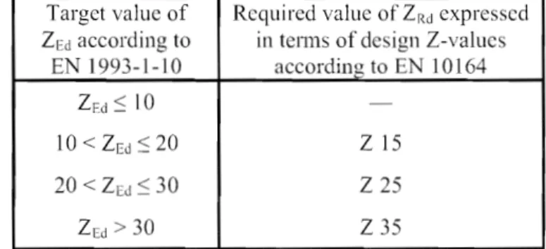
is recommended for buildings:Table 3.2: Choice of quality class according to EN 10164
Target value of Required value of ZRd expressedZEd according to in te1111S of design Z-values EN
1993-1-10
according to EN10164
::;10
-10
< :S20
Z15
20
< ZEd::;30
Z 25
EN 1993-1-1:2005 (E)
3.2.5 Tolerances
(1) The dimensional and mass tolerances of rolled steel sections, structural hollow sections and plates should con form with the relevant product standard, ET AG or ETA unless more severe tolerances are specified.
(2) For wcldcd components thc tolerances given in EN 1090 should be applied.
(3) For structural analysis and design the nominal values of dimensions should be used.
3.2.6 Design values of material coefficients
(1) The material coefficients to be adopted in calculations for the structural steels covered this Eurocode Part should be taken as follows:
modulus of elasticity
E
=
210000 N
Itnn12
shear modulus
G
=
E
~
81
000
N / mn1
22(1 v)
Poisson's ratio in elastic stage v 0,3
coefficient of linear thermal expansion
a
12
xl0-
6perK
(for T ~ 100°C)NOTE For calculating the structural effects of unequal temperatures in composite concrete-steel structures to EN 1994 the coefficient of linear thermal expansion is taken as
a
=10 10--
6perK.
3.3 Connecting devices
3.3.1 Fasteners
(1) Requirements for fasteners are given in EN 1993-1-8. 3.3.2 Welding consumables
(1) Requ irements for welding consumables are given in EN 1993-1-8.
3.4 Other prefabricated products in buildings
(l)B Any semi-finished or finished structural product used in the structural design of buildings should comply with the relevant EN Product Standard or ET AG or ETA.
4 Durability
(1) The basic requiremcnts for durability are set out in EN 1990.
~(2)P The means of executing the protective treatment undertaken off-site and on-site shall be In
accordance with EN 1090.
NOTE EN 1090 lists the factors affecting execution that need to be specified during design.
(3) Parts sLisceptible to corrosion, mechanical wear or fatigue should be designed such that inspection, maintenance and reconstruction can be carried out satisfactorily and access is available for in-service inspection and maintenance.
EN 1993-1-1:2005 (E)
(4)8 For building structures no fatigue assessment is normally required except as follows: a) Melnbers supporting lifting appliances or rolling loads
b) Members subject to repeated stress cycles from vibrating machinery c) Members subject to wind-induced vibrations
d) Members subject to crowd-induced oscillations
~(5)P For elements that cannot be inspected an appropriate corrosion allowance shall be included. @i)
(6)B Corrosion protection does not need to be applied to internal building structures, if the internal relative humidity does not exceed 80%).
5 Structural analysis
5.1 Structural modelling for analysis
5.1.1 Structural modelling and basic assumptions
~(l)P Analysis shall be based upon calculation models of the strueture that are appropriate for the limit
state under consideration. @i)
(2) The calculation model and basic assumptions for the calculations should reflect the structural behaviour at the relevant limit state with appropriate accuracy and reflect the anticipated type of behaviour of the cross sections, members, joints and bearings.
~(3)P The method used for the analysis shall be consistent with the design assumptions. @i)
(4)B For the structural modelling and basic assumptions for components of buildings see also EN 1993-1-5 and EN 1993-1-11.
5.1.2 Joint modelling
(1) The effects of the behaviour of the joints on the distribution of internal forces and moments within a structure, and on the overall deformations of the structure, may generally be neglected, but where such effects are significant (such as in the case of semi-continuous joints) they should be taken into account, see EN 1993-1-8.
(2) To identify whether the effects of joint behaviour on the analysis need be taken into account, a distinction may be made between three joint models as follows, see EN 1993-1-8, 5.1.1 :
simple, in which the joint may be assumed not to transll1it bending moments;
con6nuous, in which the behaviour of the joint may be assumed to have no effect on the analysis; selni-continuous, in which the behaviour of the joint needs to be taken into account in the analysis (3) The requirements of the various types of joints are given in EN 1993-1-8.
5.1.3 Ground-structure interaction
(1) Account should be taken of the deformation characteristics of the supports where significant.
EN 1993-1-1:2005 (E)
5.2 Global analysis
5.2.1 Effects of deformed geometry of the structure
(I) The internal forces and moments may general1y be determined using either: first-order analysis, using the initial geometry of the structure or
second-ordcr analysis, taking into account the influence of the deformation of the structure.
(2) The effects of the deformed geometry (second-order effects) should be considered if they increase the action effects significantly or modify significantly the structural behaviour.
(3) First order analysis may be used for the structure, if the increase of the relevant internal forces or moments or any other change of structural behaviour caused deformations can be neglected. This condition may be assumed to be fulfilled, if the following criterion is satisfied:
Ucr Fer
~
10 for elastic analysis
FEd2::
15 for plastic analysis
(5.1 )
where Uer is the factor by which the design loading would have to be increased to cause elastic instability in a global mode
FEd is the design loading on the structure
Fer is the elastic critical buckling load for global instability mode based on initial elastic stiffnesses
NOTE A greater limit for Ucr for plastic analysis is given in equation (5.1) because structural
behaviour may be significantly influenced by non linear material properties in the ultimate limit state where a frame forms plastic hinges with moment redistributions or where significant non linear deformations from semi-rigid joints occur). Where substantiated by more accurate approaches the National Annex may give a lower limit for Ucr for certain types of frames.
(4)B Portal frames with shallow roof slopes and beam-and-column type plane frames in buildings may be checked for sway mode failure with first order analysis if the criterion (5.1) is satisfied for each storey.
In
thesc structures Uer [§) should be calculated using the following approximative formula, provided that the axial compression in the beams or rafters is not significant:
(5.2)
[§) where is the total design horizontal load, including equivalent forces according to 5.3.2(7), transfelTed by the storey (storey shear)
V[d is the total design vertical load on the frame transferred by the storey (storey thrust) @lI
b'-LEd is the horizontal displacement at the top of the storey, relative to the bottom of the storey, when the frame is loaded with horizontal loads (e.g. wind) and fictitious horizontal loads which arc applied at each floor level
h
I
I
I
/
~~-~--__ --__ --__ --__ --__
---~--~~--~r-,I
EN 1993-1-1:2005 (E)
OHEdJ
I
- - - 1
/ II
I
/ /[§)
Figure 5.1: Notations for 5.2.1 (4)
@iINOTE IS For the application of (4)B in the absence of more detailed information a roof slope may be taken to be shallow if it is not steeper that 1:2 (26°).
NOTE 2B For the application of (4)B in the absence of more detailed information the axial compression in the beams or rafters [§) should @iI be assumed to be significant if
A~
0,3
- " - y-
~f
NEd
(5.3)
where NEd is the design value of the compression force,
"A is the inplane non dimensional slenderness calculated for the beam or rafters considered as hinged at its ends of the system length measured along the beams of rafters.
(5) The effects of shear lag and of local buckling on the stiffness should be taken into account if this significantly influences the global analysis, see EN 1993-1-5.
NOTE For rolled sections and welded sections with similar dimensions shear lag effects may be neglected.
(6) The effects on the global analysis of the slip in bolt holes and similar deformations of connection devices like studs and anchor bolts on action effects should be taken into account, where relevant and significant.
5.2.2
Structural stability of frames
(1) If according to 5.2.1 the influence of the deformation of the structure has to be taken into account (2) to (6) should be applied to consider these effects and to verify the structural stability.
(2) The verification of the stability of frames or their parts should be carried out considering imperfections and second order effects.
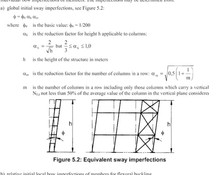
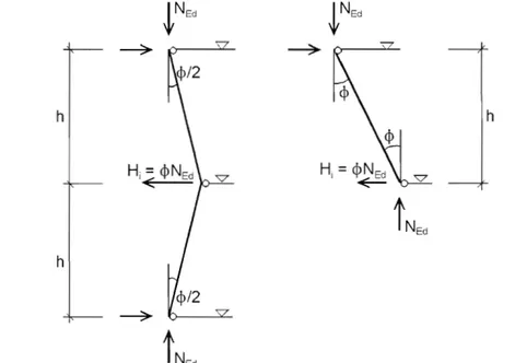
(3) According to the type of frame and the global analysis, second order effects and imperfections may be accounted for by one of the following methods:
a) both totally by the global analysis,
b) partially by the global analysis and partially through individual stability checks of members according to 6.3,
c) for basic cases by individual stability checks of equivalent members according to 6.3 using appropriate buckling lengths according to the global buckling mode of the structure.