7 MONITORING OF LASER
VAPORIZATION OF ACRYLIC
POLYMERS
This chapter deals with the monitoring process of an innovative technique concerning CO2 laser machining of polymers. CO2 laser machining represents a
flexible technique for the rapid fabrication of miniaturized polymer structures such as micro-fluidic devices or moulds for the drop-casting of thermoset resins.
A model to estimate the main dimensions (depth and width) of the grooves produced by the IR-laser on a suitable thermoplastic polymer (PMMA) is presented, by means of the monitoring process of the main parameters (incident power, scanning speed). Starting from this theoretical model it will be shown how it is possible to engrave a complex system of channels for the production of cheap micro-fluidic devices to be used as a single-use alternative to glass or silicon technologies of the conventional products.
IR laser vaporization can be also adopted for the removal of a single layer of PMMA. This is achieved using multiple overlapping sequences of straight grooves with different scanning directions. The proposed technique shows that the removal depth varies proportionally with the number of layers machined, while surface roughness is influenced by the grooves spacing and the orientation of the scanning direction between successive layers.
A method for thermally bonding the PMMA sheets, constituting the 3D structure of the chip, is also presented. The combination of high temperatures and a low bonding pressures makes it possible to generate a bulk junction enabling good performances in terms of sealing characteristics.
7.1 INTRODUCTION
The fabrication of microstructures in a suitable plastic material can be obtained by material addition techniques or removal processes.
The first group includes all the techniques of increasing material layer by layer using various approaches such as selective laser sintering of polymeric powders [1] or stereolitography of liquid thermoset resins [2].
A second approach involves removal techniques such as conventional milling processes and laser machining. In milling, micro-cavities with sculptured surfaces or sharp corners can be obtained using spherical cutting tools, whose diameter determines process resolution. On the other hand, the use of small tool diameters strongly limits process parameters and, particularly, feed rates.
Material removal on polymers can also be obtained using low power lasers [3]. The material is rapidly heated to become molten and then burned or even vaporized, according to the interaction time, radiation intensity and polymer properties. High energy density associated to the focused laser spot allows a relevant resolution during cutting. This procedure can obtain very small details or radii, difficult to be achieved using conventional milling.
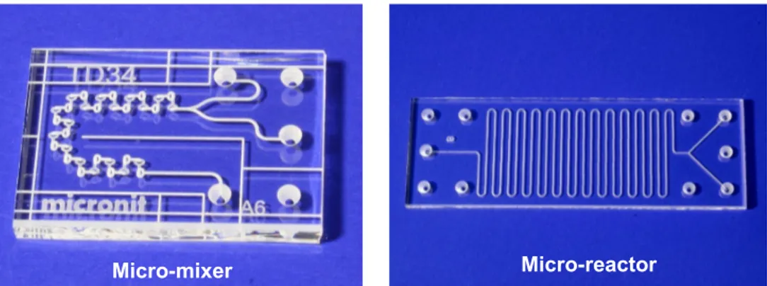
Micro-fluidic systems are used for various kinds of bio-chemical analyses, such as waste water monitoring, and for medical applications, such as drug delivery and point-of-care diagnostics. Liquids and gasses conveyed in channels, with cross-sectional dimensions on the order of 10-500µm, can undergo to chemical and physical changes, mix or separate each other, when covering predetermined paths. These systems have been mostly made using conventional silicon technology. As a material, silicon is a good choice when small numbers of long-lasting systems have to be produced. However, especially in clinical applications, single-use systems are desired in order to avoid contamination. In this field polymers represent an alternative to silicon or glass since micro-fluidic systems can be produced rapidly and inexpensively using low cost polymers.
Figure 1 – Examples of micro-devices by MICRONIT® obtained by conventional glass milling.
A large number of polymer micro-fabrication technologies have been established over the recent years. These methods can be roughly divided in two groups: replication technologies, in which a master structure is replicated into the polymer
material, and the direct techniques in which each single device is manufactured separately. Replication methods such as hot embossing [4] and injection molding [5] are not only complex but also expensive compared to material removal processes like CNC milling [6] or laser machining.
Laser machining is a promising method for making polymer devices employing micro-channels not only for the speed of the fabrication process itself, but also for the high flexibility of changing the design. The material is rapidly heated, molten or even vaporized, according to the interaction time, radiation intensity and polymer properties. High energy density associated to the focused spot allows a relevant resolution during cutting, obtaining very small details difficult to be achieved by conventional milling.
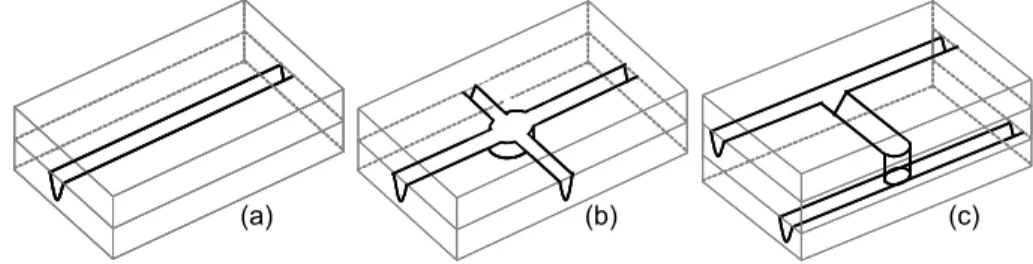
In such a way the realization of micro-fluidic devices by stacking and bonding several polymer substrates, containing laser micro-fabricated channels, offers the potential of creating complex 3D canalizations based on a relatively simple two-dimensional manufacturing processes. For this reason one of the key challenge in creating any micro-fluidic device is the development of an effective seal by affixing a cover plate to a substrate containing micro-fabricated channels (as described in Fig. 2).
Figure 2 - Main steps: (a) cutting of PMMA substrates, (b) channel fabrication, (c) thermal bonding.
7.2 IR LASER BEAM MACHINING OF POLYMERS
As far as the kind of laser sources is concerned, most organic materials are highly absorptive at CO2 laser wavelength of 10.6µm, and transparent at the most common semiconductor (0.8µm) and Nd-YAG (1.06µm) ones. All organic polymers also show an intense absorption in the ultraviolet region (excimer laser wavelengths of about 190-248nm) [7,8].
Plastic materials are commonly highly absorptive at the CO2 laser wavelength and transparent to the visible and near-infrared spectra. Machining in the IR region is generally a thermal process which produces a rapid rising of temperature of the workpiece. Energy associated to IR photons induces stretching and bending of the molecular structure which result in internal friction and heat affection on the surface. Since the beam can be concentrated into a minimum spot size which reflects the operating wavelength, channels with cross-sections lower than 100µm are difficult to be achieved. As a matter of fact continuous-wave CO2 lasers represent the best choice if high speeds of fabrication are required in addition to smoothness of the surface and accuracy in cutting.
Polymers present different behaviours at this frequency, depending on the type of material and the molecular mass. Some authors [9] subdivide polymers into three groups according to the dominant phenomenon which generates the material removal:
PMMA substrate
Laser beam Pressure
Heat Heat
− Most thermoplastics are laser machined by a “melt shearing” process: the material is melt by the laser beam which brings about this physical change disentangling the monomer chains of the bulk plastic. The small molten pool is blown away by the gas jet.
− Polymethylmethacrylate (PMMA) and polyacetals are laser machined by vaporization.
− All thermosets (e.g. phenolic or epoxy resins), and vulcanized rubbers, are laser machined by “chemical degradation”. The energy of the beam acts to break the chemical bonds by disrupting the integrity of the material.
A suitable polymer material for the production of micro-structures should not melt when irradiated since the presence of a remarkable liquid phase could cause blockage after re-solidification. For this reason thermoplastics (e.g. polyethylene) are mostly avoided. Thermosets are also not proper since the energy of the beam induces chemical degradation disrupting the integrity of the material.
On the other hand amorphous polymers especially fit in the field of laser machining since the removal mechanism is generated by vaporization which can be considered a pure sublimation process [8]. The transition from solid to vapour is carried out with the minimum amount of chemical degradation so that the cut edge is of extremely high quality and no channel blockage will occur.
7.3 INFRARED LASER VAPORIZATION OF PMMA
The polymer used in experiments was PMMA because of its low cost, high absorption of about 0.92 for infrared frequencies [10] and the capability of obtaining a high quality of the machined surfaces. The use of PMMA as the substrate material has several advantages since it is non-porous and therefore contamination caused by biomolecular adsorption is reduced. In addition PMMA is inert in neutral aqueous solution and no hydrolysis occurs during its use.
PMMA also combines a low heat capacity with a low heat conductance, which means that any absorbed heat will result in a rapidly rising of temperature. Figure 3 shows that PMMA remains in the solid glassy state until it reaches the transition temperature of about 115°C and then it becomes mouldable.
Figure 3 – Chemical changes during the warming-up of PMMA.
If more energy is added, random breaking and end-chain scission occur at temperatures between 350 and 380°C. These phenomena lead to the development of volatile monomers (MMA) without any chemical degradation so that the cut edge is of extremely high quality [11,12].
115°C
160°C
350-380°C
460°C
Solid state Mouldable state Depropagation Vaporization
115°C
160°C
350-380°C
460°C
7.4 EXPERIMENTAL SET-UP
The main purpose of this research was the development of an experimental technique for the rapid fabrication of micro-fluidic devices by CO2 laser machining of PMMA and then thermal bonding of several substrates under superimposed pressure.
A CO2 laser system with a maximum power of 50W and Gaussian TEM was used. The beam was concentrated to a minimum spot radius of 350µm by a 200mm flat-field lens. A mirror-equipped head was used to deflect the beam on the scanning surface. These movements were controlled by a 2D CAD software which allowed to set the marking path, the scanning direction and the distance between each pass. Since channels are produced by deflecting the laser radiation, the flat-field lens also allowed the beam to hit the polymer surface under an angle of 90° which results in a symmetric channel profile. The dimensions of every polymer substrate, obtained from a 2mm thick sheet, were 75 x 25 mm2.
The present study was structured into the following main steps:
− realization of a straight channel, moving the beam along a single direction (Fig. 4.a).
− Realization of blind cavities to be used as fluid collectors, machining PMMA layer by layer. The removal of each layer of material was obtained using the superposition of multiple parallel grooves (Fig. 4.b).
− Development of a sealing technique allowing the bond several PMMA substrates together. This will lead to the realization of complex 3D channel structures connecting substrates by means of feed-through holes on PMMA (Fig. 4.c).
Figure 4 - (a) simple channel (b) central collector (c) channels connection between substrates
7.5 CHANNEL PROFILE
In order to investigate the influence of the process parameters on the Gaussian profile of the channel, accurate mathematical models based on the heat balance of an infinitesimal volume have already been proposed [8, 9, 12]. These models consider that laser power is balanced by the heating of an infinitesimal volume of polymer and evaporative heat losses. From these considerations removal depth results directly proportional to the incident laser power and inversely to the scanning speed.
The model proposed in this paper assumes the removed material m to be proportional to the amount of heat Q available to vaporize the polymer [13,14,15]. This heat can be evaluated as the difference between the absorbed energy Qin and the threshold energy Qth:
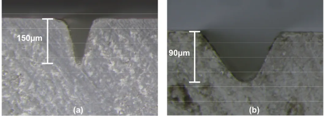
Figure 5 - Channel profiles obtained by Pin =50W and v=500m/s : (a) 200mm focal
length , (b) 210mm focal length.
)
(
Q
inQ
thk
kQ
m
=
=
−
(1) where k is a constant related to the chemical binding energy of the PMMA polymer and is generally characterized by a non-linear dependence on temperature. The threshold value represents the energy losses: there are two major loss terms which represent the energy needed to heat-up the irradiated area before vaporization begins, and the energy lost due to conduction into the surroundings.Figure 6 – Geometrical definition of the groove profile and the irradiated volume.
The absorbed energy is equal to the product of the absorption coefficient α, the incident power Pin and the irradiation time ∆t:
150µm 90µm (a) (b)
IRRADIATED VOLUME
W
W/2
D
IRRADIATED VOLUME
W
W/2
D
W
W/2
D
t
P
Q
in=
α
in∆
wherev
L
t
=
∆
(2)The irradiation time is related to the cutting speed and the effective spot size along the scanning direction L (illustrated in Fig.6). Assuming the irradiated area to be rectangular and the irradiance distribution of the nearly-Gaussian beam to be triangular, L is represented by half the groove width W.
The channel depth is related to the spot size via the density of the material ρ as follows:
(
DW
)
L
m
2
/
=
ρ
(3) Equations (1) and (2) must be substituted into equation (3) to yield the groove depth: 24
2
W
kQ
Wv
P
k
D
in thρ
ρ
α
−
⎟
⎠
⎞
⎜
⎝
⎛
=
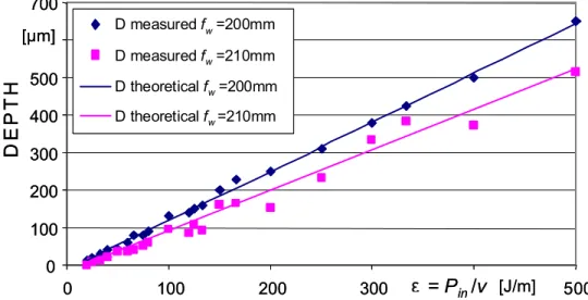
(4) It can be noted that within the limits of this simple model, the groove depth is stated to be a linear function of the ratio between incident laser power and the product of scanning speed and groove width W which is strictly dependent on the spot diameter.Figure 7 - Comparison between measured data and theoretical prediction of the groove depth D (laser focused on the surface fw=200mm and with 10mm defocus
fw=210mm).
This reflects the dependence of the vaporization process on the Energy Density mentioned in chapters 5 and 6: the model here developed based on the thermal
0 100 200 300 400 500 700 0 100 200 300 500 D measured fw=200mm D measured fw=210mm D theoretical fw=200mm D theoretical fw=210mm
e = P
in/v
DE
P
T
H
[µm] [J/m] 0 100 200 300 400 500 700 0 100 200 300 500 D measured fw=200mm D measured fw=210mm D theoretical fw=200mm D theoretical fw=210mm D measured fw=200mm D measured fw=210mm D theoretical fw=200mm D theoretical fw=210mme = P
in/v
DE
P
T
H
[µm] [J/m]ε
balance of the heat flux, leads to the same dependences of the theoretical solutions of the Fourier equation proposed in chapter 5. Furthermore, a minimum offset must be overcome before vaporization occurs, which reflects the threshold energy from equation (1).
Tests were performed to investigate the correlation between groove profile, beam speed and power. At constant power, the scanning laser speed was increased by 25mm/s steps between 25mm/s and 125mm/s. This was repeated at different powers between 2.5W and 12.5W. Shorter times of machining can be realized using the maximum laser power (50W) and high scanning speeds (500-1000mm/s), obtaining however values of energy density within the range of this simple model.
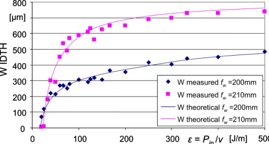
Figure 8 - Comparison between measured data and theoretical prediction of the groove width W (laser focused on the surface fw=200mm and with 10mm defocus
fw=210mm).
Data collected in this study showed an effective correspondence with the proposed model. As far as the groove depth D is concerned (figure 7), the experimental results were used to obtain least-squared lines showing a maximum standard deviation of 20µm from the model in the case of high powers or low scanning speeds, where conductive heat losses are more relevant. If the beam is 10mm defocused over or under the surface, using the same input power and scanning speed of the focused condition, the vaporization depth decreases uniformly. This is due to the enlargement of the spot diameter which causes a reduction of the energy density available on the PMMA surface. It can be noted also that a 10mm defocus resulted in higher threshold energy and higher dispersion of the experimental data.
The groove width is not linearly linked with energy density ε (figure 8). It tends to assume a limit value corresponding to the spot diameter Φspot which varies with the focal length f. The empirical formulation adopted to predict the groove width is:
0 100 200 300 400 500 600 800 0 100 200 300 500 W measured fw=200mm W measured fw=210mm W theoretical fw=200mm W theoretical fw=210mm
W ID
T
H
[J/m] [µm]ε = P
in/v
0 100 200 300 400 500 600 800 0 100 200 300 500 W measured fw=200mm W measured fw=210mm W theoretical fw=200mm W theoretical fw=210mm W measured fw=200mm W measured fw=210mm W theoretical fw=200mm W theoretical fw=210mmW ID
T
H
[J/m] [µm]ε = P
in/v
⎥
⎥
⎦
⎤
⎢
⎢
⎣
⎡
⎟⎟
⎠
⎞
⎜⎜
⎝
⎛
−
−
−
Φ
=
3exp
1
c
W
th spotε
ε
(5) where εth represents the threshold value of the energy density (evidenced in Fig.7 and 8) while c3 is an experimental constant which correlates Φspot with ε used for the vaporization process.The previous empirical equation for the groove width W was derived by a non linear regression of the acquired data, carrying out a correlation index of about 0.95 for a focal length of 200mm and 0.93 for 210mm. This is shown in Fig 8.
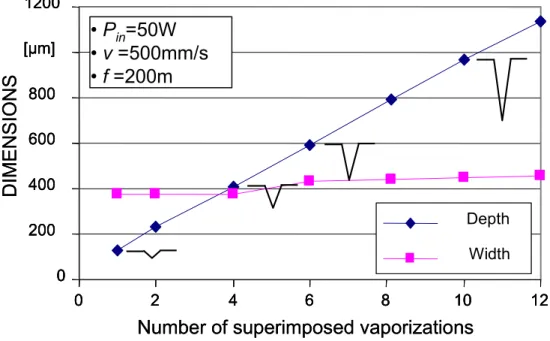
Figure 9 - Changing the channel profile by superimposed passes (Pin =50W,
v=500m/s, f=200mm).
Since the flow dynamics in the device strictly depends on the chemical and physical properties of the fluid, channel profiles different from the above mentioned results should be required in order to minimize flow resistance.
For this purpose a process enabling the channel cross section variation, by using a predetermined number of superimposed vaporizations with the same process parameters, is here proposed. Results in Fig. 9 showed that it is possible to obtain a fixed penetration rate without a sensible width increase. This is due to the fact that W depends on the useful spot size of the laser beam as defined by the diameter of the spot where the irradiance is higher than the threshold value for vaporization. The different shapes obtained by the proposed technique, should be tested in further studies to find the channel profile which allows better performances in terms of flow rate and resistance reduction.
The useful spot size is thus time dependent since the irradiance has a Gaussian distribution. As a result, a slow feed of the laser beam produces broader channels than a fast moving one. To change the channel width keeping depth constant,
Number of superimposed vaporizations
DIMENSIONS
0 200 400 600 800 [µm] 1200 0 2 4 6 8 10 12 Depth Width• P
in=50W
• v =500mm/s
• f =200m
Number of superimposed vaporizations
DIMENSIONS
0 200 400 600 800 [µm] 1200 0 2 4 6 8 10 12 0 200 400 600 800 [µm] 1200 0 2 4 6 8 10 12 Depth Width Depth Width• P
in=50W
• v =500mm/s
• f =200m
channels with different number of passes were cut, keeping the scanning speed constant at 500mm/s and varying the incident power proportionally.
Figure 10 - Width variation at constant depth and development of channel bulges (v=500mm/s, f=200mm).
Results shown in Fig. 10 demonstrated that a higher number of passes at lower laser power generated narrower channels since the amount of energy conduced in the surroundings did not exceeded the removal temperature. The x axis represents the polymer surface while the broken lines define the channel profiles obtained by using different combination of number of passes and incident laser power.
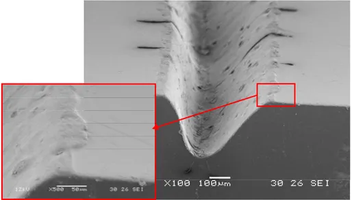
Figure 11 – Formation of channel bulges after 10 passes at Pin=5W, v=500mm/s,
f=200mm. PMMA SURFACE CHANNEL BULGES
[µm]
[µm]
-150 -100 -50 50 -300 -200 -100 100 200 300 1pass , 50W 4 passes , 12.5W 10 passes , 5 W 20 passes , 2.5W v=500mm/s , f=200mm PMMA SURFACE CHANNEL BULGES[µm]
[µm]
-150 -100 -50 50 -300 -200 -100 100 200 300 1pass , 50W 4 passes , 12.5W 10 passes , 5 W 20 passes , 2.5W v=500mm/s , f=200mm 1pass , 50W 4 passes , 12.5W 10 passes , 5 W 20 passes , 2.5W v=500mm/s , f=200mmA secondary phenomenon correlated with this procedure was also noticed: increasing the number of passes, large bulges developed over the cutting edges (as shown in the SEM picture in Fig. 11).
This particular behaviour, measured by an optical microscope and plotted in Fig. 10, was probably due to the softening of polymer density caused by the irradiation which results in an increase in volume and therefore a rising of the polymer material. Decreasing molecular weight was more pronounced for channels that have been cut several times at low power since the polymer thermal diffusivity is very low and the heat affected zone results larger. Another reason leading to observable bulges at the channel edges, is the deposition and solidification of melted material which is ejected out by the high pressure of the hot gasses evolving from the kerf.
7.6 BLIND CAVITIES
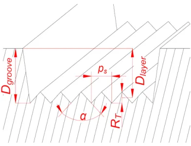
In order to collect or distribute fluids in the device, blind cavities can be obtained using a layer by layer technique based on the removal of multiple parallel grooves machined side by side with partially superimposed profiles as shown in Fig.8.a.
Figure 12 - Geometrical superposition of parallel grooves.
The spacing between each groove represents the scanning step (ps) and influences the depth of the layer (Dlayer) and the roughness of the machined surface:
2
T groove layerR
D
D
=
−
(6) where Dgroove is given by equation (4) and RT is the roughness of the machined surface related to ps by:⎟
⎠
⎞
⎜
⎝
⎛
=
2
cot
2
α
s Tp
R
(7) Equations (6) and (7) state that Dlayer linearly depends on RT and ps (for constantα). To investigate the influence of these parameters, several tests were carried out
by vaporizing rectangular layers on the surface of PMMA with Pin = 50W,
v=500mm/s, focal length of 200mm and ps ranging between 25 and 250µm.
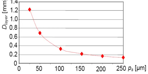
Figure 13 - Relation between layer depth Dlayer and scanning step ps (Pin = 50W, v =
500mm/s, f = 200mm).
Measured data revealed, instead, that the layer depth was inversely proportional to
ps (Fig. 13). The reason for this behaviour was not predictable with the geometrical relations (6) and (7). Instead it can be traced back to the much bigger number of passes needed to machine the same rectangular layer using small values of the scanning step (25µm and 50µm). The irradiation time increases and a large amount of heat cannot be eliminated by conduction due to the low thermal diffusivity of PMMA. The polymer surface and its substrate are then in a permanent mouldable state which allows higher Dlayer than the value predicted by the equation (6).
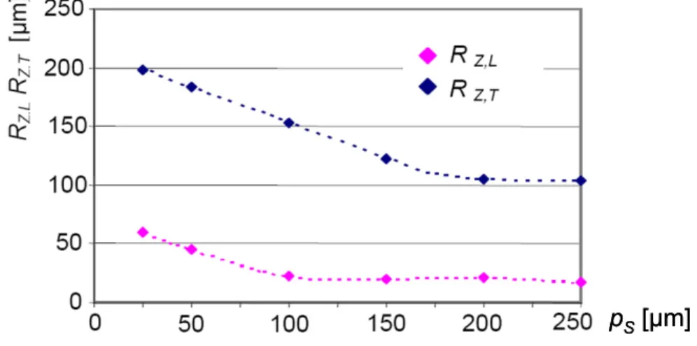
Surface analysis showed asperities regularly distributed across the scanning direction only for ps within 100µm and 250µm. For lower values (25µm and 50µm), they assumed a random distribution due to an irregular overlap of the cutting edges on the mouldable surface. Measurements of roughness (RZ) were carried out along the scanning direction (longitudinal roughness RZ,L) and perpendicularly to it (transversal roughness RZ,T). Contrary to the equation (7), a reduction of ps involved a relevant increase in RZ,T (Fig. 14). Also RZ,L presented low values and a nearly constant behaviour only for steps within 100µm and 250µm, due to the fact that the stylus runs inside a single groove.
Tests were carried out vaporizing several layers on the surface of PMMA with Pin = 50W, v = 500mm/s, focal length of 200mm and ps ranging between 25 and 250µm
ps [µm] 200
to investigate the influence of the scanning step on the layer depth and surface roughness.
Figure 14 - Relation between roughness RZ and scanning step ps (Pin = 50W, v =
500mm/s, f = 200mm).
Examples of the over mentioned effects on layer depth and roughness are given in figure 14 which shows the effect of the laser Energy Density at to different scanning steps: 250µm and 25 µm. Measured data revealed that Dlayer was inversely proportional to ps since the use of small values of the scanning step (especially 25µm and 50µm) increases the irradiation time. In this way a large amount of heat, which cannot be eliminated by conduction due to the low thermal diffusivity of PMMA, generated deeper penetrations (Fig. 15.b).
Figure 15 - Cross sections of two layers obtained by Pin =50W, v=500m/s, f=200mm
and : (a) pS=250µm, (b) pS=25µm.
To achieve a higher cavity depth in addition to a better flatness of the machined surface, layers were successively machined alternating the scanning along two perpendicular directions. This procedure allowed a remarkable reduction of roughness by the effect of a limited defocus which decreased the energy density
ps [µm]
Dlayer=150µm Dlayer=1240µm
(a) (b)
p
S[µm]
and consequently, the penetration in the substrate. The spot was refocused on the machined surface after the vaporization of every couple of crossed layers. In these conditions it was verified that increasing the number of crossed layers, the cavity depth varied proportionally while roughness assumed limit values of about 50µm.
Figure 16 – Strategy for surface flattening Pin =50W, v=500m/s, f=200mm,
pS=150µm.
The removal of a number N of successive layers, with the same scanning direction and process parameters, cannot allow cavities with a requested depth (Dcavity) by simply applying the following intuitive relation:
N
D
D
cavity=
layer×
(8) This was due to the beam reflection on the surface asperities which hindered a uniform removal depth. In order to get a better quality of the machined surface, the layers were successively machined alternating the scanning along two perpendicular directions, as shown in Fig.15.This procedure allowed a reduction of RZ by the effect of a limited defocus which decreased the energy density and consequently, the penetration in the substrate. Removal depth after 2 crossed layers (D2cross) resulted lower than 2·Dlayer .
Since a predetermined Dcavity has to be reached, scanning steps giving constant values of D2cross have to be established. Tests were performed machining 4 consecutive layers with ps varying within the above mentioned range. The spot was refocused on the machined surface after the vaporization of every couple of crossed layers. For ps = 25-50µm, variable D2cross were obtained due to the mouldable consistency of the substrate, affected by residual heat.
To obtain a reliable and fast process, lower values of ps have to be avoided while
ps = 100µm is excluded due to the high longitudinal roughness obtained. For ps = 150-200-250µm, the removal depths after two crossed layers were respectively 0.47mm, 0.31mm and 0.26mm, while the surface roughness were included between 60µm and 90µm.
7.7 BONDING PMMA SUBSTRATES
Several methods for bonding PMMA substrates have been already proposed including thermal methods (in boiling water [16] or with heated weights [17]), microwave welding [18], solvent bonding [19] and thermal lamination [20]. At the most basic level, if gluing substrates together afford adequate seal, this approach can be often limited by the high risk of channel blockage. Thermal lamination with polyethylene films is a more common solution which can be achieved using standard industrial apparatus at temperatures of about 100°C. However, when the channel is defined by two different materials non-homogeneities in chemical composition can cause band broadening during the analysis of the fluid [21]. Hence, direct thermal bonding approaches are especially desirable as they allow formation of enclosed micro-channels with uniform surfaces composed entirely of the same polymeric material. The combination of high bonding pressure (about 6.5MPa) and temperature just over the glass transition value (115°C) [22] induces global and localized deformations of the substrates or leaves an interfacial layer with significant thickness variation. For this reason to guarantee the structural integrity of the polymeric substrates and avoid channel blockage, thermal bonding with lower pressure is desired.
7.8 THERMAL BONDING
The novel idea to join a laser-machined substrate with a cover sheet was to use channel bulges created during the laser machining (illustrated in Fig.18.a), as additive polymer material to obtain a leakproof autogenous sealing. Since bulges had very small dimensions, only low bonding pressures are needed to overcome their compression strength. In this way, combining low pressure at the interface and temperature higher than the glass transition value, it was possible to generate first of all a gluing rim along the channel edges which allowed contain fluids and then a bulk junction which guaranteed substrates cohesion and stiffness of the whole device structure (Fig. 18.b).
For the experimental implementation a convectional oven was equipped with an electronic thermostat which allowed to control the environment temperature. The PMMA sheets were positioned between two aluminum plates (3mm of thickness) which transferred heat by conduction achieving an uniform distribution on the contact
surface. Bonding pressure could be adjusted by controlling loads applied on the top of the upper plate and it was kept in the range of 10-15kPa. Prior to the bonding process parts were carefully cleaned with ethanol to avoid any kind of chemical contamination which could generate vapor inclusions during the heating process.
Figure 18 - (a) View of a laser machined channel, (b) channel cross section after thermal bonding.
The PMMA sheets were heated to 145°C in 10 min, and then they were pressed at this temperature for 30min. Next the bonded stack was cooled down to 80°C and annealed at this temperature for other 20 min to relieve stresses (Fig. 19). Then the bonded device was finally cooled to room temperature. The whole process took approximately 1.5 hours which is considerably shorter than other conventional thermal processes in which bonding took about 3 hours.
Figure 19 – Thermal cycle for the joining of 2 PMMA substrates.
7.9 BONDING STRENGHT CHARACTERIZATION
Since the commonly used fluidic devices have to stand at a working pressure in the range of 100-500kPa [23], the bonding between two PMMA substrates has been tested in these conditions checking the presence of any leakage. Devices characterized by a simple cross geometry were designed, in order to verify the
(a)
(b)
bulges bulges0
25
50
75
100
[°C]
150
0
10
20 30
40
50 60
70
80 [min] 100
BONDING TIME
TEMPERATUR
E
Bonding pressure
10kPa
0
25
50
75
100
[°C]
150
0
10
20 30
40
50 60
70
80 [min] 100
0
25
50
75
100
[°C]
150
0
10
20 30
40
50 60
70
80 [min] 100
BONDING TIME
TEMPERATUR
E
Bonding pressure
10kPa
effective seal of micro-channels over the entire surface of the junction. Channels having 250µm width and 100µm depth have been firstly tested by a 100kPa pressure in order to check if the bulges softening could cause blockages of the liquid flow. The PMMA device was then tested plugging the three exits and increasing the fluid pressure in steps of 100kPa for a fixed duty cycle of 5min. No leakages from the channel have been noted up to a 1MPa. If more pressure was added, fluid began to leak from the entry side; this was probably due to the widening of the channel compared to the diameter of the feeding needle (350µm) which was forced in. This limit value was anyway retained to be adequate for the preliminary fabrication of PMMA microfluidic devices allowing a remarkable safety factor.
Figure 20 – Micro-device obtained by the proposed technique and details during the mixing process
This limit value was anyway retained to be adequate for the preliminary fabrication of PMMA microfluidic devices allowing a remarkable safety factor. An example of device obtained by the proposed technique is given by the micromixer shown in Fig. 20. Channels were designed in order to mix two different fluids injected in channels and collected outside by means of needles. The feeding pressure of the incoming fluids was kept at a constant value of about 100kPa and the mixed solution was driven out in a syringe at atmospheric pressure.
7.10 CONCLUSIONS
In this chapter an experimental technique for microfluidic device fabrication was developed and successfully implemented. CO2 laser micromachining was used to obtain channels on PMMA. Depths ranging between 50-600µm and widths between 150-400µm were achieved by adjusting the laser power and scanning speed. Instead of conventional bonding processes a low-pressure/high-temperature approach was
preferred to assure structural integrity of the PMMA substrates and avoid channel blockage. The measured bonding strength during pressure tests was as high as 1MPa, and examination of cross section of the microchannels validates the good sealing quality. Even if bulk thermal joining fit better into a lab environment due to its extensive bonding times, this new methodology for generation of microfluidic structures should facilitate the fabrication of microdevices at low cost, and it could be widely used in biological applications. With increasing fluidic complexity, bonding technologies that enable selective sealing are required. The possibility of localizing heat exactly at the desired bond position should reduce the risk of structure deformation and channel clogging.
7.11 REFERENCE
[1] Berzins M., Childs T.H.C., Ryder G.R.,1996, The Selective Laser Sintering of Polycarbonate, Annals of the CIRP, 45/1:187-191.
[2] Colton J.S., Crawford J., Pham G., Rodet V., 2001, Failure of Rapid Prototype Molds During Injection Molding, Annals of the CIRP, 50/1: 129-132.
[3] Tönshoff H.K., Hesse D., Mommsen J., 1993, Micromachining Using Excimer Lasers, Annals of the CIRP, 42/1: 247-251.
[4] Gerlach A., Knebel G., Guber A. E., Heckele M., Herrmann D., Muslija A., Shaller T., 2002, Microfabrication of single-use plastic microfluidic device for high-throughput screening and DNA analysis, Microsyst. Technol. 7 265-8. [5] Rötting O., Ropke W., Becker H., Gartner C., 2002, Polymer microfabrication
technologies, Microsyst. Technol. 8 : 32- 6.
[6] McKeown P., 1996, From micro- to nano-machining towards the nanometre era, Sensor Review, 16 : 4-10.
[7] Srinivasan R., 1993, Ablation of polymethil methacrilate films by pulsed (ns) ultraviolet and infrared (9.17 µm) lasers: a comparative study by ultrafast imaging, Journal of Applied Physics, 73 : 2743-50.
[8] Berrie P.G., Birkett F.N., 1980, The drilling and cutting of polymethylmethacrylate (Perspex) by CO2 laser, Optics and Laser in Engineering, 1 : 107-129.
[9] Atanasov P.A., Baeva M.G., 1997, CW CO2 laser cutting of plastics, Proc. SPIE 3092 : 772-5.
[10] Arisawa H., Brill T.B., 1997, Kinetics and mechanism of flash pyrolysis of polymethyl methacrylate, Combustion and Flame 109 : 415-26.
[11] Holland B.J., Hay J.N., 2002, The effect of polymerisation conditions on the kinetics and mechanism of thermal degradation of PMMA, Polymer Degradation and Stability, 77 : 435-439.
[12] Yuan D., Das Y., 2007, Experimental and theoretical analysis of direct-write laser micromachining of polymethyl methacrylate by CO2 laser ablation, Journal of Applied Physics 101, 024901.
[13] Romoli L., Tantussi G., Dini G., 2007, Layered Laser Vaporization of PMMA Manufacturing 3D Mould Cavities, CIRP Annals - Manufacturing Technology, v 56, n 1, p 209-212.
[14] Jia F., Galea E.R., Patel M.K., 1999, The numerical simulation of the noncharring pyrolysis process and fire development within a compartment, Applied Mathematical Modelling, 23 : 587-607
[15] Snakenborg D., Klank H., Kutter J.P., 2004, Microstructure fabrication with a CO2 laser system, J. Micromech. Microeng. 14 : 182-189.
[16] Kelly R. T., Woolley A. T., 2003, Thermal bonding of polymeric capillary electrophoresis microdevices in water, Anal. Chem. 75 1941–5.
[17] Ford S. M., Davies J., Kar B, Qi S. D., McWhorter S., Soper S. A. , Malek C. K., 1999, High-aspect ratio micromachining in polymethylmethacrylate (PMMA) using x-ray lithography for the fabrication of micro-electrophoresis devices, J. Biomech. Eng. 121 13.
[18] Yussuf A. A., Sbarski I., Hayes J. P., Solomon M., Tran N., 2005, Microwave welding of polymeric-microfluidic devices, J. Micromech. Microeng. 15 1692– 9B.
[19] Brown L., Koerner T., Horton J. H., Oleschuk R. D., 2006, Fabrication and characterization of poly(methylmethacrylate) microfluidic devices bonded using surface modifications and solvents, Lab. Chip 6 66–73.
[20] McCormick R. M., Nelson R. J., AlonsoAmigo M. G., Benvegnu F., Hooper H. H., 1997, Microchannel electrophoretic separations of DNA in injection-molded plastic substrates, Anal. Chem. 69 2626–30.
[21] Bianchi F., Wagner F., Hoffmann P., Girault H. H., 2001, Electroosmotic flow in composite microchannels and implications in microcapillary electrophoresis systems, Anal. Chem. 73 829–36.
[22] Shadpour H., Musyimi H., Chen J. F., Soper S. A., 2006, Physiochemical properties of various polymer substrates and their effects on microchip electrophoresis performance, J. Chromatogr. A 1111 238–51.
[23] Nagas K., Jiang L., 2007, A polymer microfluidic multiplexer, IEEE Southeastcon., Mar 22-25 2007 Richmond VA, Unites States.