1 Optical Sampling
1.1 Optical sampling: applications and motivations
Ultrahigh-bit-rate optical communication technology has rapidly progressed during the past few years, so the need for an optical waveform measurement scheme with improved time resolution has arisen.
Optical sampling is an equivalent-time sampling technique based on all-optical cross correlation between the signal under test and a train of short sampling pulses with a repetition rate lower than the bit rate, allowing conveniently slow data acquisition.
As the repetition rate increases, ultra-short pulses play a key role in data trasmissions and therefore this makes necessary the use of optical network subsystem such as ultra-fast label processor, ultra-fast optical clock recovery, ultra-fast signal regeneration, ultra-fast optical flip-flop etc. In such applications an instrument able to measure optical signal with sub-picosecond time resolution is essential.
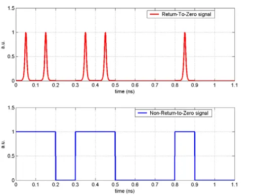
First of all we have to understand that there are two main type of line code used in telecommunications signal: Non-Return-to-Zero (NRZ) and Return-to-Zero (RZ). A Non-Return-to-Zero (NRZ) line code is a binary code in which "1's" are represented by one significant condition and "0's" are represented by the other significant condition, with no other neutral or rest condition. In this case it is possible to find where the pulses
fronts are but it is hard to reconstruct the clock, so a synchronization signal must also be sent alongside the code.
On the other hand, Return-to-Zero (RZ) describes a line code in which the signal drops (returns) to zero between each pulse. This takes place even if a number of consecutive zeros or ones occur in the signal (Fig. 1.1). This kind of signal is self clocking, this means that a separate clock does not need to be sent alongside the signal, but suffers from using more bandwidth to achieve the same data-rate as compared to Non-Return-to-Zero format.
Fig 1.1: Example of RZ (in the bottom) and NRZ signal (on the top)
At the beginning the Time Division Multiplexing technique (TDM) was chosen to allow the trasmission of a large amount of data. TDM allows to split in several time channel the great transmitting capacity of the fiber. But modulation complexity and the growth of the need to have high speed transmission bring to use a complementary technique: the Wavelength Division Multiplexing (WDM) [1].
WDM systems allow to transmit in fiber a lot of signal on different wavelength without interfere each other. Every wavelength represent an optical channel. Actually there are some prototypes of systems where the TDM technique is put on every single WDM channel [1].
It is also important to underline that there are optical devices such Mode-Locked Fiber Laser which can generate pulses with a very short temporal length (ultra-short pulses). Using this type of pulses it is possible to decrease the bit time and this is the reason why RZ codes play a key rule in optical communications.
In OTDM (Optical Time Division Multiplexing) systems, ultra-short pulses are used to allow signal multiplation with high bit-rate performances. So the interest in ultrashort pulses has grown, due to the request of high bit-rate transmission systems and characterization of the dynamics in many ultrafast nonlinear optical devices. The need for resolving optical signals beyond the limited time resolution of modern oscilloscopes can be satisfied by optical samplers.
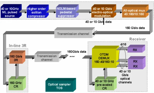
An example of OTDM system was implemented in the italian national laboratory of photonic networks CNIT-CEIIC, in Pisa, where I worked on this thesis. Such OTDM system works at 160 Gbit/s and it is scalable up to 640 Gbit/s. In Figure 1.2 is reported this OTDM system. The OTDM transmitter have to generate a pulse train at tributary rate with a pulsewidth suitable for a transmission at the aggregate bit rate, then each pulse train is modulated by conventional electro-optical devices and optically multiplated by using different optical delay lines. In this case the pulse source is realized by active fiber mode locking technique. An higher order soliton compressor reduces the pulsewidth lower than 1ps and a NOLM-based [2] pedestal suppressor removes the undesirable tails. The in-line 3R (reshape, regenerate, clock recovery) process is achieved by a recovery clock that exploit an optical PLL (Phase Locked Loop) including an active fiber mode locked laser in regenerative configuration modeled as optical VCO (Voltage Control Oscillator), and an optical ultra-fast phase detector. The reshaper is implemented by a three-stage NOLM-based scheme [3]. Finally at the receiver the demultiplexing is obtained by a simple NOLM structure [4].
The purpose of this type of experiments is to surpass electronics limits which keep the maximum bit rate at 40 Gbit/s.
Fig. 1.2: Setup of the OTDM system implemented in CNIT laboratories.
Other than telecommunication application, optical sampling is also important in biomedical field, for example in Ultrasound Modulated Optical Tomography (UMOT) [5]. This application allows a good test of human body inner tissue, without using X-ray which are detrimental for human being.
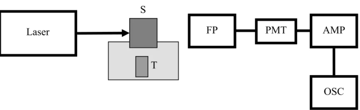
In Figure 1.3 there is a scheme of the UMOT system, in which light is modulated by ultrasounds because if that didn’t happen, the signal could be scattered by internal tissues losing its informations. Ultrasound modulation takes place making optical signal propagates into a turbulent channel, as shown in Figure 1.4, which allows signal’s polarization oscillations promoting light to get through body tissues.
Optical sampling is capital in signal reception, because the obtained signal is monitored with an oscilloscope.
S
Fig. 1.3: setup of UMOT system. S: signal sample; FP: Fabry-Perot receiver; PMT: photomultiplating tube; AMP:
amplificator; T: ultrasound transducer.
1.2 Optical sampling techniques
The most important application of optical sampling consists in the characterization of the dynamics in many ultrafast optical devices, indeed the need for resolving optical signals beyond the limited time resolution of modern oscilloscopes can be satisfied by optical samplers. So, all-optical solutions for performance monitoring become important.
To estimate the goodness of a signal we can consider several factors but the bit error rate (BER) is the most accurate signal quality measure and, in combination with synchronous eye-diagram monitoring, a complete picture of the signal quality is obtained. However, the BER cannot be monitored in active networks but must be approximated by the Q-value.
Asynchronous all-optical sampling is a potentially cost effective Q-value monitoring method since it is bit rate transparent and requires no electronic clock recovery; the asynchronous Q-values are sensitive to amplitude-related detrimental effects, but do not detect problems related to timing jitter, and due to sampled data from the transitions between marks and spaces the Q-value becomes inaccurate.
Synchronous all-optical sampling systems can provide both accurate Q-value and pseudo-real-time eye-diagram monitoring. Based on high-resolution eye-diagrams, detrimental effects such as chromatic dispersion, PMD and third-order dispersion can be identified and analyzed. However, conventional synchronization of the sampled data
Laser FP PMT AMP
T
requires that the repetition rate of the optical data signal is recovered, which is difficult and expensive at extreme bit rates. The clock recovery also makes the sampling system bit rate and modulation dependent.
In another way, we can differentiate synchronous and asynchronous sampling referring to data acquisition speed. Indeed in synchronous samplers data are recorded in the time domain for different delay times, the delay time is often varied with a mechanical delay line, realized for example with a corner cube on a motorized translation stage. This approach limits the speed with which a range of delays can be realized, and consequently the speed with which whole transmission spectra can be recorded.
Much faster data acquisition is possible with asynchronous sampling, but in this case several problems are in post-processing which could be very hard and expensive.
Another way of sampling is using mixed techniques in which the scan range of the signal is not limited as in synchronous sampling, and the post-processing is not necessary, indeed a time-axis rescale is enough.
1.2.1 Synchronous sampling
Synchronous sampling is more difficult than other sampling techniques as it relies on a stable, high-quality pulse source. However, it has great advantages: Q-measurements are much more sensitive and the limiting signal degradation mechanism can be identified directly from the eye-diagram.
An example of synchronous optical sampler [6] was implemented in 2005 in the CNIT-CEIIC laboratory in Pisa. It is based on nonlinear effects in a 1 meter-long bismuth oxide fiber with a nonlinear coefficient γ=1250 W-1km-1, which is 100 times the standard value of Highly NonLinear Fibres (~10 W-1km-1). In particular this sampler exploits the polarization state rotation induced by XPM (Cross-Phase Modulation), which will be better explained in the next chapter.
The operating principle of this type of sampler is that an ultra-short pulsed pump with high peak power interacts with the signal under test while propagating in the
nonlinear fiber. A quasi-instantaneous (<50 fs) phase rotation is induced by the sampling pulse on the signal portion superimposed to the pump. When opportune launching conditions are satisfied, the phase shift directly translates in a polarization rotation. By means of a polarization controller and a polarizer at the output of the nonlinear element it is possible to extract the portion of the signal time overlapped to the pump. This portion can be measured by using a narrow-bandwidth photodiode. If the pump pulse is short enough the measured power can be approximated with the instantaneous signal power. Shifting the pump with respect to the signal its time shape can be reproduced.
We must pay attention to the fact that the high nonlinear coefficient of the bismuth oxide fiber permits to strongly decrease the fiber length and the use of short fiber spans reduces at the same time the polarization fluctuations and the scheme footprint, making the system more stable and compact.
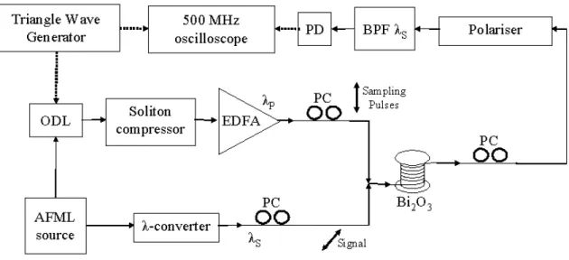
In Figure 1.4 is shown that the signal is distorted through soliton propagation in HNLF (High Non Linear Fiber, that is a special type of fiber with high non linear coefficent where it is possible to exploit nonlinearities in few meter; nonlinear effects in fiber will be explained later) and it is coupled with the pump with a 45°-rotated polarization state in order to obtain maximum XPM-induced polarization rotation. It is also possible to see that a piezo-electric ODL (Optical Delay Line) driven by a 100 Hz electrical triangle wave shifts the sampling pulses with respect to the signal.
In this case the probe signal and the samplig pulse are generated by the same source and this method has the drawback that there is the necessity of a compression and of a λ-convertion stages which could introduce noise in the system. There are other schemes where the two signals (sampling pulse and probe signal) come from two different sources, so there is not the necessity of a compressor and a λ-converter but it is fundamental to synchronize each other both the frequency of the samplig pulse and the signal.
Fig. 1.4: Experimental setup of the optical sampler based on XPM-induced polarization rotation in 1 m of bismuth
oxide fiber.
The main problem with the use of an optical delay line is that the scanning range of the optical sampler could be inadequate for the purpose. To increase the scanning range it is possible to use a set-up like the one shown in Figure 1.5 [7].
Fig. 1.5: scheme used to increase the scanning range.
The sampling signal is launched through the port 1 of a circulator; the second port is connected to a polarization beam splitter that transmits the signal through the
piezo-electric delay line; a Faraday rotating mirror is then used in order to reflect the signal with a 90° rotated polarization state. The signal pass again through the delay line but this time the polarization beam splitter reflects the signal towards the orthogonal output. A standard mirror reflects the signal without changing its polarization state. The signal, reflected by the PBS, passes again through the delay line and its polarization state is rotated by the faraday mirror; then the signal passes for the fourth time through the piezo-electric delay line and is transmitted through the third port of the circulator. Such a scheme can be use for any polarization maintaining optical delay line giving a delay multiplication factor of four. So the advantage of this setting is that if we have a piezoelectric optical delay line which allows a scanning range of 25 ps (like the one which was used in the setup in Figure 1.4) we can obtain a scanning range of 25x4=100 ps which allows to analize a 10 GHz periodic signal.
1.2.2 Asynchronous sampling
The main drawback of synchronous sampling schemes is the need of a clock recovery system to synchronize optical sampling pulses with the signal under test: if the repetition rate of the analyzed signal is very high, the development of the synchronization circuitry can be very intricate and expensive. Moreover optical synchronous sampling methods can typically analyze only limited time intervals: therefore they allow to resolve only a period of a periodic signal, but not long bit sequences.
The asynchronous solution, based on the acknowledgement of the mean frequency of the signal under test, avoids the use of a clock recovery circuit, with strong advantages in terms of complexity and cost. Moreover, it allows to measure considerably longer bit sequences of the signal, with respect to synchronous schemes.
Fig. 1.6: Asynchronous optical sampling working principle
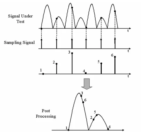
To understand how an asynchronous optical sampling works we can consider, for example, the ASOF (Asynchronous optical Sampling Oscilloscope based on Four Wave Mixing) [8].
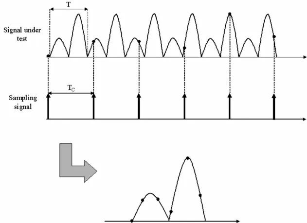
This asynchronous optical sampling oscilloscope exploits a nonlinear interaction between the signal under test and the sampling signal. The signal under test is consider to be periodic with a frequency fS=1/TS; the sampling signal is an ultra-short pulse train at low repetition rate fC=1/TC, where fC is not correlated to fS, meaning that there is any
fixed relation between the two frequencies. In this case the two optical signals are made interacting with each other by means of FWM (Four Wave Mixing, a nonlinear effect which will be illustrated later) in optical fiber: every pulse of the sampling signal generate a pulsed FWM component, whose energy is proportional to the instantaneous power of the signal under test in the corresponding interaction time.
Since the frequencies of the involved signals are not correlated, two consecutive samples do not correspond to two consecutive instantaneous power values of the signal under test; on the contrary the temporal series of the samples appears as a shuffled sampling of the signal to be analyzed. Besides, the sampled signal can be correctly reconstructed if the difference of the period length TS-TC is known. Therefore a post-processing can be applied to the sample series for re-ordering the samples and reconstructing the shape of the signal under test.
The resolution of this type of sampler is determined by the difference between the periods of the signal under test and the sampling signal, by the maximum number of acquired samples, and by the length of the time interval to be analyzed. So the possibility to finely change the period of the sampling signal allows to significantly modify the resolution of the ASOF, or the sampled time interval. For this purpose, the AMLFL (Actively Mode-Locked Fiber Laser) which generates the sampling signal, is provided with a variable optical delay line in order to vary the length of the fiber cavity, thus finely changing the repetition rate of the sampling pulse train.
1.2.3 Mixed techniques
Because of the fact that synchronous sampling methods are able to analyze limited time intervals allowing to resolve only the eye-diagram of data signal and the fact that asynchronous optical sampling methods can describe long time intervals but with longer
refresh time, high timing jitter and a hard data post-processing for reordering the samples and reconstructing the shape of the signal under test, mixed techniques are implemented with the intent of obtaining the advantages of both asynchronous and synchronous sampler.
As often as not this type of samplers are based on nonstandard phase-locked loop (PLL) which allows synchronous sampling (synchronous in the sense that the two frequencies of the sampling signal and the signal under test are fixed with a specific difference between them) of OTDM signals (or any other signal with bit rates given by integer multiples of the base rate), which would be impossible using a standard PLL [9].
The usual approach [9] is a sampling mode with the sampling frequency slightly detuned from the Nth subharmonic of the clock rate or bit rate. This scheme is in contrast with synchronous sampling where the sampling frequency is an exact subharmonic of the bit rate and it should not be confused with techniques not requiring a clock signal, so it’s easy to understand the reason why this is a mixed technique, between synchronous and asynchronous methods.
This method has the advantages of both synchronous and asynchronous samplers: namely there are no limitation for the temporal scanning range that is equal to the period of the signal under test (as for the asynchronous sampler) and no post processing to the sample sequence for samples reordering (as for the synchronous sampler). On the other hand, the drawback of the mixed technique is that it needs the RF electric clock of both signal under test and sampling pulses and the complexity of the synchronization scheme.
An example of a mixed sampler, called Quasi-Asynchronous sampler and implemented in the italian national laboratory of phonic networks CNIT-CEIIC in Pisa , will be explained in a detailed way further along.