Co-Sintering of Dense Electrophoretically Deposited YSZ Films on Porous NiO-YSZ Substrates for SOFC Applications
Giuseppe Savo, Alberto Rainer, Alessandra D’Epifanio, Silvia Licoccia, Enrico Traversa Department of Chemical Science and Technology, University of Rome Tor Vergata, Via della Ricerca Scientifica 1, 00133 Rome, Italy.
ABSTRACT
An original process for the preparation of YSZ dense films with a thickness lower than 10 µm over NiO-YSZ substrates is presented. This process involves the preparation of a green membrane of NiO-YSZ and subsequent electrophoretic deposition (EPD) of commercial YSZ powder on this polymer-rich membrane. A single thermal treatment allowed removal of the organic compounds, sintering of the layers and full densification of the electrolyte.
INTRODUCTION
Fuel cells are energy-conversion devices that transform chemical energy in electric power via the electrochemical combustion of fuel. SOFCs offer various advantages, such as greater efficiency with a wide range of fuels, negligible production of pollutants and suitable durability [1,2]. Performant SOFCs should have electrodes with good electro-catalytic properties to ensure more efficient fuel combustion and oxygen reduction and must be chemically and mechanically stable for long term operation. The electrolyte has to be a good ionic conductor to minimize ohmic loss and has to ensure gas tightness. Moreover, its thermal expansion coefficient (TEC) should be similar to the TECs of the electrodes.
Conventional SOFCs consist of a Ni-YSZ composite anode, a YSZ electrolyte and a perovskite (most commonly doped-LaMnO3) cathode and show an operating temperature around 1000°C. Such a high temperature is needed because of the ionic conductivity characteristics of YSZ. To ensure a good power density the ohmic resistance of the electrolyte must be until around 0.15 Ω cm-2. Operating at intermediate temperature allows to reduce cost and to increase reliability of SOFCs. In the case of YSZ, this resistance value can be reached at 700°C with a 15 µm high-quality dense film deposited on a porous supporting anode or cathode [3].
Several approaches have been reported in the literature for the deposition of such films:
electrochemical vapour deposition (EVD) [4], low pressure plasma spraying [5,6], RF sputtering [7], colloidal processes such as slurry-based dip or spray coating [8]. In this work electrophoretic deposition (EPD) was selected as a technique to obtain thin dense electrolyte films. EPD is a well known process that allows to obtain compact ceramic coatings with thicknesses ranging from few micrometers to several millimeters [9,10], which has been applied also in SOFC application for the preparation of YSZ films [11-15].
This paper reports a different approach from the early papers that combines EPD with a co-sintering process. Co-co-sintering has recently been investigated as a promising technique for the reduction of the number of thermal cycles needed for the preparation of SOFCs [16,17].
However, usually substrates are pre-fired at an intermediate temperature prior to deposition and co-sintering. In this work, a one-step process for the sintering of a bi-layer assembly obtained by EPD of YSZ film directly on green NiO-YSZ membranes is presented.
EXPERIMENTAL
Preparation of NiO-YSZ substrate
A commercial anodic powder, based on a mixture of NiO and YSZ (Praxair, 8 mol% YSZ, 5.3 m2g-1, d95 = 5.4 µm) was mixed with polyvinylidene fluoride (Solvay PVDF SOLEF 6020-1001) and dispersed in N-methyl-2-pyrrolidinone (Aldrich, 99% pure). The slurry obtained was spread on a glass pane yielding a green membrane with a thickness of approximately 750 µm.
Rectangular bodies of about 40 x 15 mm were cut from the membrane and used as substrates for EPD experiments.
Preparation of YSZ films using EPD
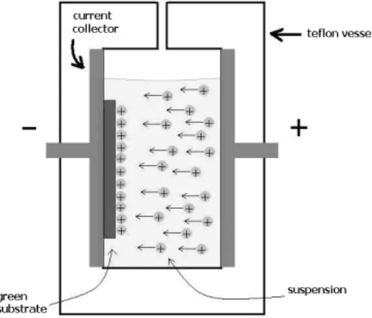
A suspension of commercial YSZ powder (Tosoh, TZ8Y, 8 mol% YSZ, d95= 2 µm ) in methanol was prepared by sonication. The cell used for the EPD experiment had a vertical setup as shown in Figure 1. The substrate was connected to the negative electrode since YSZ particles in
methanol are positively charged [10]. The distance between the current collectors was 10 mm, while the volume of the plating bath was 60 mL. A constant 100 V DC voltage was applied for a deposition time of 8 minutes, monitoring the current during the experiment. After the deposition, the samples were dried at room temperature before the co-sintering process.
Co-sintering and characterization
Thermogravimetric and differential thermal analysis (TG-DTA, Netsch STA 419) was performed on the green anodic membrane to evaluate the burn-out of the organic compounds.
Co-sintering of the anode-electrolyte bi-layer was performed in air at a temperature of 1350 °C, with a stop at 650 °C to complete the burn-out of volatile compounds. An anodic green substrate with no deposited film was added to each sintering batch, to serve as a reference for porosity investigation.
Mercury porosimetry (Carlo Erba Instruments, Micropores 2000) was performed on uncoated sintered anodes to characterize the pore size distribution. The measurements were performed on anodes sintered for 4 h and 6 h , and on a commercial anode (INDEC) for sake of comparison.
Field Emission Scanning Electron Microscopy (FE-SEM, Leo Supra 1535) was used to investigate the morphology of the anodes and the electrolyte films.
Energy Dispersion Spectroscopy (EDS, Oxford Instruments) was used to obtain compositional maps of the sintered bodies.
RESULTS AND DISCUSSION
Properties of NiO – YSZ anodes
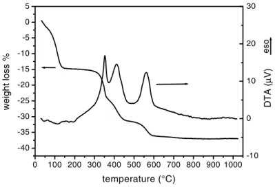
The paramount step of the co-sintering process is the strict control of thermal treatments that cause oxidative decomposition of volatile compounds in the green substrate. A vigorous gas release during heating can determine the spalling of the coating and the formation of huge cracks. TG-DTA was used with the purpose of determining the correct thermal treatment to guarantee an uniform and slow burning process. Figure 2 shows the TG-DTA curves performed on green membranes. The weight loss ended at 600 °C, and therefore during the sintering a very slow heating rate was maintained up to 650 °C to ensure a slow burning process.
0 100 200 300 400 500 600 700 800 900 1000 -40 -35 -30 -25 -20 -15 -10 -5 0 5 w e ight l o ss % temperature (°C) -10 0 10 20 30 es o DT A ( µ V)
Figure 2: TG-DTA analysis of green membranes used as anodic substrate.
Figure 3: EDS analysis of the commercial NiO-YSZ powder (a) and of fired anodic substrate(b).
0 1 2 3 4 5 6 7 8 9 10 a Ni Ni Zr O Y Ni in te n s it y ( a .u .) energy (keV) 0 1 2 3 4 5 6 7 8 9 10 b Ni Ni Zr O Y Ni in te n s it y ( a .u .) energy (keV)
Table 1. Porosity and specific surface area values for three different anodes. Sample ID 4h 6h Commercial Porosity (%) 46.2 17.6 14.7 Surface area (m2/g) 1.16 0.35 1.46 1000 10000 100000 1000000 1E7 0 10 20 30 40 50 60 70 80 d is tri but ion ( % )
pore size (angstrom)
commercial 4 hours 6 hours
Figure 4. Pore size distribution for the anodes sintered at 4 h and 6 h, compared to a commercial anode.
During sintering process, evaporation of nickel oxide can occur, resulting in a compositional change on sintered bodies. Figure 3 reports the results EDS analysis performed both on starting powder (Fig. 3a) and on a large area of the anode (about 80 x 60 µm) after sintering (Fig. 3b). As it can be observed, the ratio between YSZ and nickel is only slightly affected by the thermal treatment; such a small nickel loss does not compromise catalytic activity in operating
conditions.
Table 1 and Figure 4 show the results of mercury porosimetry. Two samples, sintered for 4 and 6 hours respectively (labelled 4h and 6h), were analyzed; a commercial NiO-YSZ supporting anode was taken as a reference. The commercial anode shows a pore size distribution strictly centred around 1 µm, whereas the samples prepared in the present work showed a higher total porosity value and a distribution of pore radius spread in 1-10 µm range. Therefore, the fully sintered anodes posses a larger porosity than the commercial anode, that is only pre-fired at lower temperature.
Microstructure of YSZ deposited films
In an EPD experiment the right choice of the solvent used during the deposition has a significant importance. As reported in the literature [15], ethanol is often used since it has a quite slow evaporation rate, so the risk of fractures when the green deposit dries is low. Methanol was used instead of ethanol, because it is slightly more acidic than ethanol and has a lower viscosity. Figure 5 shows the top and the cross section view of the YSZ film deposited on a Ni-YSZ cermet and co-fired at 1350 °C for 6 hours. After this firing process a fully dense film is formed. As it can be observed from Figure 5b, a dense, 6-8 µm thick film was obtained, with a very good
adhesion between the anode and the electrolyte. Only some submicrometric pores can be observed in the cross section, but their presence does not compromise gas tightness of the electrolyte. While the YSZ electrolyte film was dense, a porous structure was maintained in the anode. Figure 6 shows the EDS mapping relative to the same cross section, identifying the compositional pattern of the sample. No significant contamination of the electrolyte due to the evaporation of nickel oxide during sintering was observed, as evidenced by the line scan for Ni Kα radiation.
The small dishomogeneity in thickness observed in the sintered deposit is probably related to the growth of YSZ layer on the substrates by aggregation of particles in “islands” that grow under the influence of lateral forces covering the substrate, as shown with other colloids [19, 20]. CONCLUSIONS
An original process is presented to produce dense YSZ films with thickness lower than 10 µm on supporting NiO-YSZ anodes prepared starting from commercial powders.
Figure 5. FE-SEM micrographs of the plan view (Figure 5a) and the cross section (Figure 5b) of the half cell obtained after co-sintering at 1350 °C for 6 hours.
Figure 6. EDS mapping of the cross section of a half cell, featuring a line scan for Ni Kα radiation.
Electrophoretic deposition and co-sintering approach have been combined in an original process that allows to obtain anode-supported half cells with a single thermal cycle, depositing the electrolyte film on a polymer-rich anodic membrane. Characterization of the anodes shows a good residual porosity with an uniform pore-size distribution after the sintering process. Morphological evaluation of the deposited films shows the absence of cracks and a very good adhesion to the anodic substrate, with no relevant diffusion of nickel through the electrolyte thickness. The possibility to use a single sintering step and commercially available powders make this method very promising for reducing manufacturing time and cost of SOFC components.
REFERENCES
1. N.Q. Minh, J. Am. Ceram. Soc., 76, 563-588 (1993)
2. N.Q. Minh and T. Takahashi in Science and Technology of Ceramic Fuel Cells, Elsevier, New York, (1995)
3. B.C.H. Steele, J. Mater. Sc., 36, 1053-1068, (2001)
4. S.C. Singhal, in Recent Progress in Tubular Solid Oxide Fuel Cells (SOFC V), pp. 37-50 U. Stimming, S.C. Singhal, H. Tagawa and W. Lehnert Editors, The Electrochemical Society Proceeding Series, Pnennington, NJ, (1997)
5. S.P.S. Badwal and K. Foger, Ceram. Int., 22, 257-265, (1996) 6. B.C.H. Steele, Ceram. Int., 19, 269, (1993)
7. A.R. Nicoll, A. Salito, and K. Honegger, Solid State Ionics, 52, 269-275, (1992)
8. S.J. Visco, C. Jacobson, and L.C. De Jonghe, in Recent Progress in Tubular Solid Oxide Fuel
Cells (SOFC V), pp. 710-717, U. Stimming, S. C. Singhal, H. Tagawa and W. Lehnert
Editors, The Electrochemical Society Proceeding Series, Pnennington, NJ, (1997) 9. D.U.K. Rao and E.C. Subbarao, Amer. Ceram. Soc. Bull., 58, 467, (1979)
10. K. Yamashita, M. Nagai, T. Umegaki, J. Mater. Sc., 32, 6661-6664, (1997) 11. P. Sarkar and P. Nicholson, J. Am. Ceram. Soc., 79, 1987-2002, (1996) 12. T. Ishihara, K.Sato, Y. Takita, J. Am. Ceram. Soc., 79, 913-919, (1996)
13. T. Ishihara, K. Shimose, T. Kudo, H. Nishiguchi, T. Akbay, and Y. Takita, J. Am. Ceram.
Soc., 83, 1921-1927, (2000)
14. H. Negishi, N. Sakai, K. Yamaji, T. Horita and H. Yokokawa, Journal of the
Electrochemical Society, 147, 1682-1687, (2000)
15. Z. Peng, M. Liu, J. Am. Ceram. Soc., 84, 283-288, (2001)
16. K. Kobayashi, I. Takahashi, M. Shiono and M.Dokiya, Solid State Ionics, 152-153, 591-596, (2002)
17. Y. Matsusaki, I. Yasuda, Solid State Ionics, 152-153, 463-468, (2002)
18. B. Ferrari, R. Moreno, Journal of the Electrochemical Society, 147, 2987-2992, (2000) 19. S. A. Guelcher, Y. Solomentsev, J.L. Anderson, Powder technology, 110, 90-97, (2000) 20. C. Dushkin, T. Miwa b, K. Nagayama, Chemical Physics Letters, 285, 259–265, (1998)