ScienceDirect
Available online at Available online at www.sciencedirect.comwww.sciencedirect.com
ScienceDirect
Structural Integrity Procedia 00 (2016) 000–000
www.elsevier.com/locate/procedia
2452-3216 © 2016 The Authors. Published by Elsevier B.V.
Peer-review under responsibility of the Scientific Committee of PCF 2016.
XV Portuguese Conference on Fracture, PCF 2016, 10-12 February 2016, Paço de Arcos, Portugal
Thermo-mechanical modeling of a high pressure turbine blade of an
airplane gas turbine engine
P. Brandão
a, V. Infante
b, A.M. Deus
c*
aDepartment of Mechanical Engineering, Instituto Superior Técnico, Universidade de Lisboa, Av. Rovisco Pais, 1, 1049-001 Lisboa,
Portugal
bIDMEC, Department of Mechanical Engineering, Instituto Superior Técnico, Universidade de Lisboa, Av. Rovisco Pais, 1, 1049-001 Lisboa,
Portugal
cCeFEMA, Department of Mechanical Engineering, Instituto Superior Técnico, Universidade de Lisboa, Av. Rovisco Pais, 1, 1049-001 Lisboa,
Portugal
Abstract
During their operation, modern aircraft engine components are subjected to increasingly demanding operating conditions, especially the high pressure turbine (HPT) blades. Such conditions cause these parts to undergo different types of time-dependent degradation, one of which is creep. A model using the finite element method (FEM) was developed, in order to be able to predict the creep behaviour of HPT blades. Flight data records (FDR) for a specific aircraft, provided by a commercial aviation company, were used to obtain thermal and mechanical data for three different flight cycles. In order to create the 3D model needed for the FEM analysis, a HPT blade scrap was scanned, and its chemical composition and material properties were obtained. The data that was gathered was fed into the FEM model and different simulations were run, first with a simplified 3D rectangular block shape, in order to better establish the model, and then with the real 3D mesh obtained from the blade scrap. The overall expected behaviour in terms of displacement was observed, in particular at the trailing edge of the blade. Therefore such a model can be useful in the goal of predicting turbine blade life, given a set of FDR data.
© 2016 The Authors. Published by Elsevier B.V.
Peer-review under responsibility of the Scientific Committee of PCF 2016.
Keywords: High Pressure Turbine Blade; Creep; Finite Element Method; 3D Model; Simulation.
* Corresponding author. Tel.: +351 218419991.
E-mail address: [email protected]
2452-3216 © 2016, PROSTR (Procedia Structural Integrity) Hosting by Elsevier Ltd. All rights reserved. Peer review under responsibility of the Scientific Committee of PCF 2016.
10.1016/j.prostr.2016.06.184
Procedia Structural Integrity 2 (2016) 1451–1456
© 2016, PROSTR (Procedia Structural Integrity) Hosting by Elsevier Ltd. All rights reserved. Peer-review under responsibility of the Scientific Committee of PCF 2016.
10.1016/j.prostr.2016.06.184
ScienceDirect
Structural Integrity Procedia 00 (2016) 000–000www.elsevier.com/locate/procedia
2452-3216 © 2016 The Authors. Published by Elsevier B.V.
Peer-review under responsibility of the Scientific Committee of ECF21.
21st European Conference on Fracture, ECF21, 20-24 June 2016, Catania, Italy
Design and characterization of a small-scale solar sail deployed by NiTi
Shape Memory actuators
Girolamo Costanza
a*, Maria Elisa Tata
aa Dipartimento di Ingegneria Industriale, Università di Roma-Tor Vergata, Via del Politecnico 1, 00133 Roma - Italy
Abstract
Solar sails exploit the radiation pressure as propulsion system for the exploration of the solar system. Sunlight is used to propel space vehicles by reflecting solar photons from a large and light-weight material, so that no propellant is required for primary propulsion. Kapton seems to be the most suitable material for the sail production and in the space missions till now activated booms as deployment systems have always been used. In this work a self deploying system based on NiTi Shape Memory wires has been designed and manufactured in a small-scale prototype. As kapton has always been employed with a thin Al coating on one or both surfaces of the sail, for the first experiments commercial pure Al thin sheets have been used in order to simulate the sail. In the small-scale prototype manufactured, three different configurations have been studied for bending the sail while two different Nitinol wires have been used as active materials for the self-deployment of the sail. Infrared lamps have been employed in order to warm the solar sail and obtain the activation of the shape memory active elements.
© 2016 The Authors. Published by Elsevier B.V.
Peer-review under responsibility of the Scientific Committee of ECF21.
Keywords: Solar sail, Shape memory Alloy, Self-deployment systems.
1. Introduction
Solar sails exploit the light of the sun as propulsion system (Gregorio et al.). According to this relatively novel propulsion system no chemical propellant is necessary for imparting motion in the space. The basic concept of solar sailing is thus the use of quantum packets of energy (solar radiation pressure) to propel a spacecraft potentially providing a continuous acceleration limited only by the lifetime of sail material in the space environments (Tsuda et al. 2011). A great number of photon in the sunshine light interacts with the solar sail and produces a small radiation pressure on the sail itself (Leipold et al. 2003, Colin et al. 2004). For this reason, in order to exploit this propulsion system, a great surface of the sail is required, and materials employed for the construction of the sail must be lightweight and high reflectivity (Block et al. 2011). Ion propulsion engines for small satellites are based on the
Available online at www.sciencedirect.com
ScienceDirect
Structural Integrity Procedia 00 (2016) 000–000www.elsevier.com/locate/procedia
2452-3216 © 2016 The Authors. Published by Elsevier B.V.
Peer-review under responsibility of the Scientific Committee of ECF21.
21st European Conference on Fracture, ECF21, 20-24 June 2016, Catania, Italy
Design and characterization of a small-scale solar sail deployed by NiTi
Shape Memory actuators
Girolamo Costanza
a*, Maria Elisa Tata
aa Dipartimento di Ingegneria Industriale, Università di Roma-Tor Vergata, Via del Politecnico 1, 00133 Roma - Italy
Abstract
Solar sails exploit the radiation pressure as propulsion system for the exploration of the solar system. Sunlight is used to propel space vehicles by reflecting solar photons from a large and light-weight material, so that no propellant is required for primary propulsion. Kapton seems to be the most suitable material for the sail production and in the space missions till now activated booms as deployment systems have always been used. In this work a self deploying system based on NiTi Shape Memory wires has been designed and manufactured in a small-scale prototype. As kapton has always been employed with a thin Al coating on one or both surfaces of the sail, for the first experiments commercial pure Al thin sheets have been used in order to simulate the sail. In the small-scale prototype manufactured, three different configurations have been studied for bending the sail while two different Nitinol wires have been used as active materials for the self-deployment of the sail. Infrared lamps have been employed in order to warm the solar sail and obtain the activation of the shape memory active elements.
© 2016 The Authors. Published by Elsevier B.V.
Peer-review under responsibility of the Scientific Committee of ECF21.
Keywords: Solar sail, Shape memory Alloy, Self-deployment systems.
1. Introduction
Solar sails exploit the light of the sun as propulsion system (Gregorio et al.). According to this relatively novel propulsion system no chemical propellant is necessary for imparting motion in the space. The basic concept of solar sailing is thus the use of quantum packets of energy (solar radiation pressure) to propel a spacecraft potentially providing a continuous acceleration limited only by the lifetime of sail material in the space environments (Tsuda et al. 2011). A great number of photon in the sunshine light interacts with the solar sail and produces a small radiation pressure on the sail itself (Leipold et al. 2003, Colin et al. 2004). For this reason, in order to exploit this propulsion system, a great surface of the sail is required, and materials employed for the construction of the sail must be lightweight and high reflectivity (Block et al. 2011). Ion propulsion engines for small satellites are based on the
principle that a small but constant pressure applied on a wide surface of the sail can produce a satisfying acceleration to the whole structure (Johnson, Young et al. 2011).
The main space missions on this theme are reported in the following:
1973: Mariner 10 (Nasa): radiation pressure has been employed for the attitude control (Mariner 10, Nasa); 1999: Odyssee project (DLR-ESA): laboratory deployment test (Leipold et al. 1998);
2010: Ikaros (JAXA): first space probe employing successfully satellite solar sails propulsion up to Venus (Mori et al. 2009; Tsuda et al. 2011);
2011: Nanosail-D2 (Nasa): applicability study of the solar-sail propulsion to small satellites (Johnson, Whorton et al. 2011);
2015: Lightsail-1 (Planetary Society): solar sail totally displayed without reaching the orbit (Neherenz et al. 2010).
Many different systems have been till now considered for the deployment of the sails, each of them characterized by the presence of guide rollers, electromechanical actuation devices or composite booms (Fernandez et al. 2011). The main limit of the actual deployment technology is the high weight of the system and the complexity of the mechanism for the deployment of such huge surfaces. Objective of the present work is to propose, manufacture and test an innovative self-deployment system actuated by shape memory alloy elements.
2. Solar sail materials and shape memory alloys
The choice of the materials is fundamental in order to achieve the best performance in terms of active surface, number of possible folding and lightness of the structure (Kezera 2009; Dalla Vedova et al. 2011). For this reason thin films (2,5 m) of adhesive kapton (1,4 g/cm3) can be applied on thin commercial aluminum films (12 m).
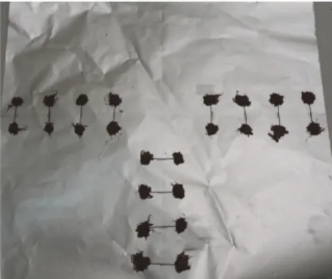
Kapton is chemically inert, shows a high radiation resistance and maintains stable its physical and chemical properties also at high temperature. Aluminum has been chosen for the high reflectivity in the whole solar spectrum and the relatively high melting point. In this stage of the work main attention was focused on the aluminum film upon which some active shape memory alloys elements has been inserted perpendicularly to the bending line. A sketch of an aluminum sail is reported in Fig. 1: it is evident the presence of silicone employed for fixing the shape memory wires to the aluminum sail.
Fig. 1 – Aluminum thin foil with shape memory elements inserted in correspondence of the folding lines.
For what concerns the active elements, NiTi shape memory wires have been chosen as active materials. Shape memory alloys are a class of functional materials able to recover the preset shape just upon heating above a critical transformation temperature (Costanza et al. 2016). The shape recovery is based on the thermoelastic martensitic transformation occurring in such kind of alloys and the characteristic transformation temperature is function of the composition of the alloy and of the thermal and mechanical history of the material (Costanza et al. 2014). Typical transformation temperatures are 45-65 °C (alloy H) and 65-95 °C (alloy M) according to the nomenclature used by the supplier of the alloys (Memory Metalle). Usually employed as sensor, sensor/actuators or only actuators, shape memory alloys are able to bear also high number of activation cycles (Costanza et al. 2010), but in this application no cycling is required to the alloys because the self-deployment of the sail must occur just once. As active material,
wires of 0.41 and 0.6 mm diameter have been identified and selected. In order to set the shape to be recovered while heating, a particular thermal treatment has been identified, usually called shape-setting. It consists in heating up to 500 °C while the wire is kept straight on a flat bed, maintaining at this temperature for 5 minutes and finally quenching in cold water. After this treatment, bent in cold condition the wire is able to recover the preset straight shape just upon heating above the activation temperature (65-95 °C). On the aluminum surface the shape memory wire were bonded by high temperature silicone (red spots in Fig. 3 b).
3. Sail geometry
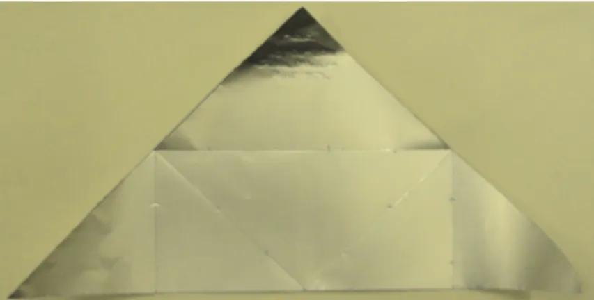
The main goal of this work was to define the bending configuration which permits a good reduction of the surface when the sail is packed but at the same time adequate planarity when the sail is completely deployed. Some experiments have been performed in order to achieve this task and for all the tests the maximum effort has been addressed to place the wire at constant distance one from the other so that the force is uniformly distributed while the sail is opening. In this way it has been possible to reduce the total number of wires and at the same time the weight of the structure. For what concerns the shape an isosceles triangle has been selected, 20 cm base and 10 cm height, for a total area of 100 cm2 in this small-scale configuration (Fig. 2). Three different folding tests have been
studied and performed, as described in detail in the successive paragraph.
Fig. 2 – The isosceles aluminum triangle (20 cm base and 10 cm height) selected for the small-scale solar sail prototype.
FOLDING TEST 1 (Fig. 3)
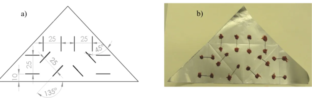
4 Nitinol wires diameter 0.41 mm and 2 cm length; 2 Nitinol wires diameter 0.41 mm and 4 cm length; 3 Nitinol wires diameter 0.6 mm and 6 cm length; Surface reduction -52%;
Deployments: 3
Fig. 3 – a) Sketch of folding test 1 (dimension reported in mm); b) Prototype of test 1, the upper triangle apex doesn’t open.
principle that a small but constant pressure applied on a wide surface of the sail can produce a satisfying acceleration to the whole structure (Johnson, Young et al. 2011).
The main space missions on this theme are reported in the following:
1973: Mariner 10 (Nasa): radiation pressure has been employed for the attitude control (Mariner 10, Nasa); 1999: Odyssee project (DLR-ESA): laboratory deployment test (Leipold et al. 1998);
2010: Ikaros (JAXA): first space probe employing successfully satellite solar sails propulsion up to Venus (Mori et al. 2009; Tsuda et al. 2011);
2011: Nanosail-D2 (Nasa): applicability study of the solar-sail propulsion to small satellites (Johnson, Whorton et al. 2011);
2015: Lightsail-1 (Planetary Society): solar sail totally displayed without reaching the orbit (Neherenz et al. 2010).
Many different systems have been till now considered for the deployment of the sails, each of them characterized by the presence of guide rollers, electromechanical actuation devices or composite booms (Fernandez et al. 2011). The main limit of the actual deployment technology is the high weight of the system and the complexity of the mechanism for the deployment of such huge surfaces. Objective of the present work is to propose, manufacture and test an innovative self-deployment system actuated by shape memory alloy elements.
2. Solar sail materials and shape memory alloys
The choice of the materials is fundamental in order to achieve the best performance in terms of active surface, number of possible folding and lightness of the structure (Kezera 2009; Dalla Vedova et al. 2011). For this reason thin films (2,5 m) of adhesive kapton (1,4 g/cm3) can be applied on thin commercial aluminum films (12 m).
Kapton is chemically inert, shows a high radiation resistance and maintains stable its physical and chemical properties also at high temperature. Aluminum has been chosen for the high reflectivity in the whole solar spectrum and the relatively high melting point. In this stage of the work main attention was focused on the aluminum film upon which some active shape memory alloys elements has been inserted perpendicularly to the bending line. A sketch of an aluminum sail is reported in Fig. 1: it is evident the presence of silicone employed for fixing the shape memory wires to the aluminum sail.
Fig. 1 – Aluminum thin foil with shape memory elements inserted in correspondence of the folding lines.
For what concerns the active elements, NiTi shape memory wires have been chosen as active materials. Shape memory alloys are a class of functional materials able to recover the preset shape just upon heating above a critical transformation temperature (Costanza et al. 2016). The shape recovery is based on the thermoelastic martensitic transformation occurring in such kind of alloys and the characteristic transformation temperature is function of the composition of the alloy and of the thermal and mechanical history of the material (Costanza et al. 2014). Typical transformation temperatures are 45-65 °C (alloy H) and 65-95 °C (alloy M) according to the nomenclature used by the supplier of the alloys (Memory Metalle). Usually employed as sensor, sensor/actuators or only actuators, shape memory alloys are able to bear also high number of activation cycles (Costanza et al. 2010), but in this application no cycling is required to the alloys because the self-deployment of the sail must occur just once. As active material,
wires of 0.41 and 0.6 mm diameter have been identified and selected. In order to set the shape to be recovered while heating, a particular thermal treatment has been identified, usually called shape-setting. It consists in heating up to 500 °C while the wire is kept straight on a flat bed, maintaining at this temperature for 5 minutes and finally quenching in cold water. After this treatment, bent in cold condition the wire is able to recover the preset straight shape just upon heating above the activation temperature (65-95 °C). On the aluminum surface the shape memory wire were bonded by high temperature silicone (red spots in Fig. 3 b).
3. Sail geometry
The main goal of this work was to define the bending configuration which permits a good reduction of the surface when the sail is packed but at the same time adequate planarity when the sail is completely deployed. Some experiments have been performed in order to achieve this task and for all the tests the maximum effort has been addressed to place the wire at constant distance one from the other so that the force is uniformly distributed while the sail is opening. In this way it has been possible to reduce the total number of wires and at the same time the weight of the structure. For what concerns the shape an isosceles triangle has been selected, 20 cm base and 10 cm height, for a total area of 100 cm2 in this small-scale configuration (Fig. 2). Three different folding tests have been
studied and performed, as described in detail in the successive paragraph.
Fig. 2 – The isosceles aluminum triangle (20 cm base and 10 cm height) selected for the small-scale solar sail prototype.
FOLDING TEST 1 (Fig. 3)
4 Nitinol wires diameter 0.41 mm and 2 cm length; 2 Nitinol wires diameter 0.41 mm and 4 cm length; 3 Nitinol wires diameter 0.6 mm and 6 cm length; Surface reduction -52%;
Deployments: 3
Fig. 3 – a) Sketch of folding test 1 (dimension reported in mm); b) Prototype of test 1, the upper triangle apex doesn’t open.
FOLDING TEST 2 (Fig. 4)
12 Nitinol wires diameter 0.41 mm and 2 cm length; Surface reduction -75%.
Deployments: 5
Fig. 4 – a) Sketch of folding test 2 (dimension reported in mm); b) Prototype of test 2, the three triangle apexes don’t open.
FOLDING TEST 3 (Fig. 5)
6 Nitinol wires diameter 0.41 mm and 2 cm length; 4 Nitinol wires diameter 0.41 mm and 4 cm length; 1 Nitinol wire diameter 0.6 mm and 6 cm length; Surface reduction -75%.
Deployments: 5
Fig. 5 – Sketch of folding test 3 (dimension reported in mm), prototype. In Fig. 7 a) – c) Three pictures of four sails, collected during the opening test with the infrared lamps, are reported.This configuration showed the best deployment of the sail.
4. Deployment experimental results
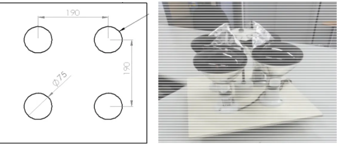
The shape memory wires activation and the sail self-deployment are due to heating when the sail is exposed to the solar radiation. In this experimental work four different heating method for the shape memory elements have been considered: oven, heating plate in contact, visible lamps and infrared lamps. In order to simulate in the laboratory the sail deployment a homogeneous heating source able to bring all the shape memory wires at the transformation temperature has been necessary. For this reason it has been decided to use four infrared lamps for warming up four sails. In this way each infrared lamp is enough to bring each triangle-shaped sail up to the activation temperature. A sketch of the device is reported in Fig. 6 a) and the device in Fig. 6 b).
a) b)
Fig. 6 – a) Sketch of the four infrared lamps heating system; b) Picture of the device.
5. Discussion and conclusions
Among the three different folding configurations the number 3 has been chosen for our experiments because showed the maximum surface reduction (-75 % in 5 folding) despite a greater length of wire was required (34 cm against 24 cm of test 2) but the highest planarity of the deployed sail has been achieved. The opening of the four sails (each one 100 cm2) happens under the effect of the infrared lamps. After turning on, the lamps start heating and
when the shape memory elements reach their activation temperature the sails start to open. The continuous heating provides energy for the self-deployment of the sails and during the whole deployment cycle, 2 minutes lasting in the laboratory test, three most significant pictures have been collected and reported in Fig. 7 a) - c).
The main objective to define and test an innovative method for the self-deployment of solar sails has been gotten. By the way some key points need to be analyzed deeper in future works, in particular:
the planarity of the sail’s surface;
the effect of the adhesive kapton on the aluminum surface; the scale effect dealing with bigger sails;
the possibility to employ shape memory alloys on the frame of the sail and not on the surface;
the effects of vacuum and the presence only of solar irradiation, excluding conduction and convection.
FOLDING TEST 2 (Fig. 4)
12 Nitinol wires diameter 0.41 mm and 2 cm length; Surface reduction -75%.
Deployments: 5
Fig. 4 – a) Sketch of folding test 2 (dimension reported in mm); b) Prototype of test 2, the three triangle apexes don’t open.
FOLDING TEST 3 (Fig. 5)
6 Nitinol wires diameter 0.41 mm and 2 cm length; 4 Nitinol wires diameter 0.41 mm and 4 cm length; 1 Nitinol wire diameter 0.6 mm and 6 cm length; Surface reduction -75%.
Deployments: 5
Fig. 5 – Sketch of folding test 3 (dimension reported in mm), prototype. In Fig. 7 a) – c) Three pictures of four sails, collected during the opening test with the infrared lamps, are reported.This configuration showed the best deployment of the sail.
4. Deployment experimental results
The shape memory wires activation and the sail self-deployment are due to heating when the sail is exposed to the solar radiation. In this experimental work four different heating method for the shape memory elements have been considered: oven, heating plate in contact, visible lamps and infrared lamps. In order to simulate in the laboratory the sail deployment a homogeneous heating source able to bring all the shape memory wires at the transformation temperature has been necessary. For this reason it has been decided to use four infrared lamps for warming up four sails. In this way each infrared lamp is enough to bring each triangle-shaped sail up to the activation temperature. A sketch of the device is reported in Fig. 6 a) and the device in Fig. 6 b).
a) b)
Fig. 6 – a) Sketch of the four infrared lamps heating system; b) Picture of the device.
5. Discussion and conclusions
Among the three different folding configurations the number 3 has been chosen for our experiments because showed the maximum surface reduction (-75 % in 5 folding) despite a greater length of wire was required (34 cm against 24 cm of test 2) but the highest planarity of the deployed sail has been achieved. The opening of the four sails (each one 100 cm2) happens under the effect of the infrared lamps. After turning on, the lamps start heating and
when the shape memory elements reach their activation temperature the sails start to open. The continuous heating provides energy for the self-deployment of the sails and during the whole deployment cycle, 2 minutes lasting in the laboratory test, three most significant pictures have been collected and reported in Fig. 7 a) - c).
The main objective to define and test an innovative method for the self-deployment of solar sails has been gotten. By the way some key points need to be analyzed deeper in future works, in particular:
the planarity of the sail’s surface;
the effect of the adhesive kapton on the aluminum surface; the scale effect dealing with bigger sails;
the possibility to employ shape memory alloys on the frame of the sail and not on the surface;
the effects of vacuum and the presence only of solar irradiation, excluding conduction and convection.
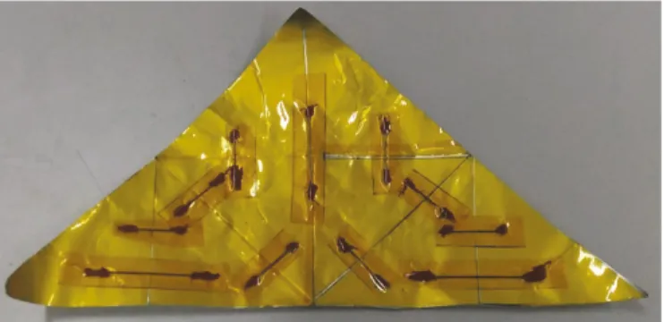
Due to torsion phenomena of the wires randomly occurring during the deployment of the sail, one aspect that will be considered in the future experiments of this research is the employment of thin flat shape memory elements obtained by rolling wires. In this way it will be possible to combine low weight, flat surface and adequate recovery force without torsion occurring. Also kapton adhesion on thin aluminum foils (an example is shown in Fig. 8) needs further investigations in order to achieve satisfying features of the manufactured sails in terms of planarity of the surface, activation time and temperature, active surface and number of folding.
Fig. 8 – Kapton adhesive films (yellow) on thin aluminum foils and shape memory active elements between them.
References
Block J., Straubel M., Wiedemann M., 2011. Ultralight deployable booms for solar sails and other large gossamer structure in space. Acta astronautica, 68 (7-8), 3984-992.
Colin R., 2004. Solar sailing: technology, dynamics and mission applications. Springer Praxis Book.
Costanza G., Paoloni S., Tata M.E., 2014. IR thermography and resistivity investigations on Ni-Ti shape memory alloys. Key Engineering Materials 605, 23-26.
Costanza G., Tata M.E., Calisti C., 2010. Nitinol one-way shape memory springs: Thermomechanical characterization and actuator design. Sensors and actuators, A: Physical 157, 113-117.
Costanza G., Tata M.E., Libertini R., 2016. Effect of temperature on the mechanical behaviour of Ni-Ti Shape Memory Sheets, TMS2016 Annual Meeting Supplemental Proceedings, 433-439.
Dalla Vedova F., Henrion H., Leipold M., Girot Th., Vaudemont R., Belmonte Th., Fleury K., Le Couls O., 2011. The Solar Sail Materials (SSM) Project – Status of activities. Advances in Space Research 48, 1922-1926.
Fernandez J.M., Lappas V.J. and Daton-Lovett A.J., 2011. Completely stripped solar sail concept using bi-stable reeled composite booms. Acta astronautica, 69, 78-85.
Gregorio A., Giannini G., Presani E., http://fisicainbarca.ts.infn.it/2005/seminari/veleSpaziali.pdf.
Johnson L., Young R., Montgomery E., Alhorn D., 2011. Status of solar sail technology within NASA. Advances in Space Research, 48 (11), 1687-1694.
Johnson, L., Whorton, M., Heaton, M., Pinson, R., Laue, G., Adams, C., 2011. NanoSail-D: a solar sail demonstration mission. Acta astronautica, 68 (5-6), 571-575.
Kezera Roman Ya., 2009. Thickness requirement for solar sail foils. Acta astronautica 65, 507-518.
Leipold M., Garner C.E., Freeland R., Herrmann A., Noca M., Pagel G., Sebolt W., Sprague G., Unckenbold W., 1998. Odissee — a proposal for demonstration of a solar sail in earth orbit, 3rd IAA International Conference on Low-cost planetary missions, Pasadena, 27 April 1 May 1998.
Leipold M., Eiden M., Garner C.E., Herbeck L., Kassing D., Niederstadt T., Kruger T., Pagel G., Rezazad M., Rozemeijer H., Seboldt W., Schoppinger C., Sickinger C., Unckenbold W., 2003. Solar sail technology development and demonstration. Acta astronautica, 52 (1-6), 317-326.
Mori O., Sawada H., Funase R., Endo T., Morimoto M., Yamamoto T., Tsuda Y., Kawakatsu Y., Kawaguchi J., 2009. Development of first Solar Power Sail Demonstrator – Ikaros, 21st International Symposium on Space Flight Dynamics (ISSFD 2009), CNES, Toulouse, France.
Nehrenz M., Diaz A., Svitek T., Biddy C., 2010. Initial design and simulation of the LightSail-1 attitude determination and control system. Proceedings of the Second International Symposium on Solar Sailing (ISSS 2010), University of New York, 135-140.
Tsuda Y., Mori O., Funase R., Sawada H., Yamamoto T., Saiki T., Endo T., Kawaguchi J., 2011. Flight status of IKAROS deep space solar demonstrator. Acta astronautica, 69, 833-840.