Facoltà di Ingegneria
Laurea Specialistica in Ingegneria dell’Automazione
Tesi di laurea
Candidato:
Matteo Tanzini
Relatori:
Prof. Andrea Caiti
Prof. Alexander Leonessa
SIGNAL PROCESSING FOR AN
AUTONOMOUS UNDERWATER VEHICLE:
AN FPGA APPROACH
Sessione di Laurea del 09/07/2009
Archivio tesi Laurea Specialistica in Ingegneria dell’Automazione Anno accademico 2008/2009
Dedico questo lavoro ai miei due
nonni che non hanno potuto avere la
soddisfazione di vedere il proprio
nipote laurearsi.
Ringraziamenti
Desidero ringraziare il Prof. Alexander Leonessa per il supporto scientifico e
morale che mi ha dato durante il mio soggiorno negli Stati Uniti; il Prof.
Andrea Caiti per la gentilezza, la disponibilità e l’aiuto dato lungo tutto lo
sviluppo di questa tesi; Gary Stein per il concreto contributo sperimentale e
il tempo dedicatomi; Marco Vincenzi per il supporto tecnico e la sua
disponibilità.
Desidero ringraziare la mia famiglia che ha sempre creduto in me e mi ha
aiutato in tutti i momenti difficili del mio percorso formativo; ringrazio mio
padre che durante tutti questi anni ha partecipato attivamente alla costruzione
della mia cultura scientifica.
Infine ringrazio la mia Giulia per avermi fatto sempre sentire speciale, in
grado di superare tutti gli ostacoli.
ABSTRACT
The idea of this thesis comes out from the participation of the University of Central Florida to the Annual International Autonomous Underwater Vehicle Competition of 2007. The goal of this competition is to build an AUV capable to accomplish to some various objectives. One of these, wants the AUV to detect an underwater acoustic ping and follow it to his source. The objective of this thesis is to improve the performance of this trajectory tracking. A Field Programmable Logic Gate Array will be used to perform an effective Digital Signal Processing.
INDEX
INTRODUCTION ... 11
DESCRIPTION OF THE OPERATIVE CONTEST ... 12
2. STATE OF ART ... 13
2.1 Autonomous Underwater Vehicles: a general view ... 13
2.1.1 Introducion ... 13
2.1.2 History ... 14
2.1.3 AUV Technology ... 16
2.1.4 The Future of AUV Technology ... 19
2.2 Simplified method for obtaining navigational information from
hydrophone arrays ... 20
2.2.1 Introduction ... 20
2.2.2 Amplifier Circuit ... 22
2.2.3 Signal processing board ... 22
2.2.4 Signal Processing ... 23
2.2.5 Results and Conclusions ... 24
2.3 Development and Testing of an Acoustic Positioning System –
Description and Signal Processing ... 24
2.3.1 General Description ... 24
2.3.2 Hardware description ... 25
2.3.3 Conclusions ... 26
2.4 Underwater Acoustic Source Localization Based on Passive
Sonar and Intelligent Processing ... 26
2.4.1 General Description ... 26
2.4.2 Acquisition, control and processing unit ... 26
2.4.3 System Software ... 27
2.4.4 Acquisition and conditioning circuit control ... 27
2.5 Field Programmable Gate Array (FPGA) ... 28
2.5.1 What is an FPGA? ... 28
2.5.2 Why do we need FPGAs? ... 30
2.5.3 Logic Block... 31
2.5.4 FPGA Routing Techniques ... 34
2.5.5 FPGA Structural Classification ... 36
2.5.6 Programming ... 38
2.5.7 FPGA Design Flow ... 40
2.5.8 Five reason to choose an FPGA ... 41
3.THE HARDWARE ... 43
3.1 How to choose an FPGA board ... 43
3.2 The Market Analysis ... 48
3.2.1 Pentek - Model 6256 ... 49
3.2.3 Echotek ECAD-DA-41-PMC ... 51
3.2.4 Bittware TETRA-PMC+ ... 52
3.3 A real choice ... 53
3.3.1 New solutions ... 53
3.3.2 The FPGA board choice: ALTERA/TERASIC DE2 Development and Education Board ... 55
3.3.4 The A/D board choice: MAX1127 Evaluation Kit from MAXIM ... 57
3.3.5 The A/D board: a self-made board ... 58
3.3.6 The Costs ... 59
3.4 Simulation’s hardware ... 59
3.4.1 Signal generation: a Digital Acquisition Board ... 60
Specifications Summary ... 60
3.5 The experimental setup ... 62
4. BORN AND DEVELOPMENT OF THE ALGORITHM ... 63
4.1 The 2007 AUVSI competition ... 63
4.2 The vehicle ... 64
4.3 The idea ... 66
4.3.1 The hydrophones ... 66
4.3.2 Issues... 67
4.4 The Mathematic Theory... 68
4.4.1 The idea ... 68
4.4.2 Extracting the Delay ... 69
4.4.3 The practice result ... 74
4.4.4 The Delay extraction ... 74
4.5 The simulation scheme ... 75
4.5.1 First blocks ... 77
4.5.2 The simulated input ... 77
4.5.3 Windowing ... 78
4.5.4 The Fast Fourier Transform ... 81
4.5.5 The product between the FFT outputs ... 87
4.5.6 The inverse Fast Fourier Transform ... 87
4.5.7 The cross correlation... 87
4.5.8 Delay Calculation ... 89
4.5.9 Results ... 90
4.5.10 Simulation Conclusions ... 94
5. IMPLEMENTATION, EXPERIMENT, RESULTS ... 95
5.1 The input signal generation ... 95
5.1.1 An acquisition tool ... 96
5.2 Sampling ... 96
5.3 The Real Scheme ... 100
5.3.1 Timing ... 103
5.4 Final Discussion and Future work ... 108
6. CONCLUSIONS ... 110
BIBLIOGRAFY ... 111
APPENDIX A – HOW TO PROGRAM AN FPGA ... 112
INTRODUCTION
The idea of this thesis starts from an Universal Central Florida’s Project aimed to participate to the AUVSI & ONR’s 10th Annual International Autonomous Underwater Vehicle Competition of 2007. The goal of the 2007 mission is to make a vehicle to autonomously navigate an obstacle course. The UCF team developed an AUV: the SCOUT.
The final obstacle the vehicle has to manage, is to identify an underwater ping and tracking it until his source.
To accomplish this, the vehicle mounts four hydrophones on his structure, in a diamond pattern. The incoming signals are treated and then sent to the Hydrophones processor to perform computations to calculate the pinger’s relative heading and distance. This trajectory tracking is the weak point of the project.
The trajectory tracking is affected by a route error equal to ± 30°. The working team found that the problem was on the low acquisition time of the digital acquisition board used for it.
The purpose of this thesis is to use a faster new technology, an FPGA board, to handle better results for the trajectory tracking.
A general research on FPGA is made to show the state of art and to understand his peculiarity. This would be an introduction to who has no knowledge on the FPGA world: this research will comprehend hardware, software and market knowledges.
To understand what kind of FPGA would have fit our needs, a choice method is created and then a real market comparison has made. Various options are evaluated and then a trade-off choice between our needs has made: we focused on performance and price.
To understand how to manage an FPGA, have been analyzed two software: a low level program language that use the Quartus II software, and a visual one, that utilize a Matlab Simulink tool, the DSP builder.
At this point, the theory is discussed: how to physically calculate the ping direction source? This comprehends the idea that comes from the hydrophones diamond pattern, how to extract the incoming signal’s data and how to apply some Digital Signal Processing to them.
A simulation study is done to understand the effective goodness of the FPGA project. The argumentation will go deep in to the FPGA programming, creating a simulation scheme only on Simulink DSP Builder Software and then fitting that scheme, to a real simulation with real simulated inputs and dealing with the FPGA board directly.
At last the results and the limitation of the algorithm are analyzed and some purpose are made for future workers on the real project.
DESCRIPTION OF THE OPERATIVE CONTEST
This thesis was developed in two different contests: the first one was the department of Mechanical, Materials, and Aerospace Engineering at University of Central Florida, America, the other one was the department of Electric systems and Automation of Engineering at University of Pisa.
On the first contest, it was possible to stay in touch with the Scout’s developing team and to benefit of all the knowledge of Prof. Alexander Leonessa, our supervisor, furthermore it was possible to use the laboratories resources and the University’s funding. At UCF was developed the research and the theoretical simulation part of the thesis while the Italy experience was focused on the real implementation in laboratory.
To stay at UCF was really useful dealing with the real beneficiaries of this thesis directly. Choices and requests were made in real time. Furthermore it was easier to contact directly lot of hardware manufacturers to get information about our needs.
At University of Pisa the supervision passed to Prof. Andrea Caiti. Here we were able to use laboratories to build up our hardware and we had the support of the department technicians and a lot of useful lab facilities and tools.
2. STATE OF ART
The bibliographic research comprehends three sections.
The first section will introduce you in the world of the Autonomous Underwater Vehicles.
In the second section three experiences similar to our’s will be described. The first experience is born form the same competition that the UCF team was involved. The system results similar to our one because the AUV, developed by the team, extracts the necessary informations from an hydrophone’s array performing some DSP analysis with an FPGA and a microcontroller. The second experience discuss about an USBL Acoustic positioning System for an underwater vehicle: they use an FPGA doing some DSP. In the third experience an FPGA is used to process source localization based on a passive sonar.
The third section will give a wide view about FPGA.
2.1 Autonomous Underwater Vehicles: a general view [1][2]
2.1.1 Introducion
An Autonomous Underwater Vehicle (AUV) is a robotic device that is driven through the water by a propulsion system, controlled and piloted by an onboard computer, and maneuverable in three dimensions. This level of control, under most environmental conditions, permits the vehicle to follow precise preprogrammed trajectories wherever and whenever required. Sensors on board the AUV sample the ocean as the AUV moves through it, providing the ability to make both spatial and time series measurements. Sensor data collected by an AUV is automatically geospatially and temporally referenced and normally of superior quality. Multiple vehicle surveys increase productivity, can insure adequate temporal and spatial sampling, and provide a means of investigating the coherence of the ocean in time and space.
The fact that an AUV is normally moving does not prevent it from also serving as a Lagrangian, or quasi Eulerian, platform. This mode of operation may be achieved by programming the vehicle to stop thrusting and float passively at a specific depth or density layer in the sea, or to actively loiter near a desired location. AUV’s may also be programmed to swim at a constant pressure or altitude or to vary their depth and/or heading as they move through the water, so that undulating sea saw survey patterns covering both vertical and/or horizontal swaths may be formed. AUV’s are also well suited to perform long linear transects, sea sawing through the water as they go, or traveling at a constant pressure. They also provide a highly productive means of performing seafloor surveys using acoustic or optical imaging systems.
When compared to other Lagrangian platforms, AUV’s become the tools of choice as the need for control and sensor power increases. The AUV’s advantage in this area is achieved at the expense of endurance, which for an AUV is typically on the order of 8- 50 hours. Most vehicles can vary their velocity between 0.5 and 2.5 m/s. The optimum speed and the corresponding greatest range of the vehicle occur when its hotel load (all required power except propulsion) is twice the propulsive load. For most vehicles, this occurs at a velocity near 1.5 m/s.
The degree of autonomy of the robot presents an interesting dichotomy. Total autonomy does not provide the user with any feedback on the vehicle’s progress or health, nor does it provide a means of controlling or redirecting the vehicle during a
mission. It does, however, free the user to perform other tasks, thereby greatly reducing operational costs, as long as the vehicle and the operator meet at their duly appointed times at the end of the mission. For some missions, total autonomy may be the only choice; in other cases when the vehicle is performing a routine mission, it may be the preferable mode of operation.
Bidirectional acoustic, radio frequency, and satellite based communications systems offer the capability to monitor and redirect AUV missions worldwide from a ship or from land. For this reason, semi-autonomous operations offer distinct advantages over fully autonomous operations. 2.1.2 History
The following presents highlights of some notable achievements in the history of AUV’s. In the short space and time available, it is unfortunately not possible to provide information on all systems.
The origin of AUV’s should probably be linked to the Whitehead Automobile “Fish” Torpedo. Robert Whitehead is credited with designing, building, and demonstrating the first Torpedo in Austria in 1866. Torpedoes are named after the Torpedo fish, which is an electric ray capable of delivering a stunning shock to its prey. Whitehead’s first torpedo achieved a speed of over 3.0 m/s and ran for 700 m. The vehicle was driven by compressed air and carried an explosive charge. If one ignores the fact that it carried an explosive charge, it might be considered the first AUV.
The need to obtain oceanographic data along precise trajectories and under ice motivated Stan Murphy, Bob Francois, and later Terry Ewart of the Applied Physics Laboratory of the University of Washington to begin development of what may have been first “true” AUV in the late 1950’s. Their work led to the development and operation of The Self Propelled Underwater Research Vehicle(s) (SPURV). SPURV I, became operational in the early 60’s and supported research efforts through the mid 70’s. SPURV I displaced 480 kg, and could operate at 2.2 m/s for 5.5 hours at depths to 3 km. The vehicle was acoustically controlled from the surface and could autonomously run at a constant pressure, sea saw between two depths, or climb and dive at up to 50 degrees. Researchers used the vehicle to make CT measurements along isobaric lines in support of internal wave modeling [1]. The vehicle was used later in the 70’s to support observations of Horizontal and Vertical Diffusion using a dye tracer at depths to 1 km. The vehicle was able to track the dye plume 66 hours after the dye was released [2]. SPURV II was more capable than SPURV I, and was used to study the dispersion of submarine wakes using a dye tracer during the 70’s and 80’s. There were over 400 SPURV deployments. The Naval Ocean System Center, now SPAWAR, began development of the Advanced
Unmanned Search System (AUSS) in 1973 in response to the sinking of the USS Thresher, the USS Scorpion, and the H bomb loss of Palomares. The vehicle was launched in 1983, and reports and publications on the system were still in press in the 90’s. AUSS displaced 907 kg, carried 20 kw-hours of energy in silver zinc batteries, and was rated to 6 km. It had an acoustic communication system that transmitted video images through the water. AUSS completed over 114 dives, some to 6 km. The concept of using multiple free swimming vehicles to improve system performance can be traced
Figure 1 - Robert Whitehaed with his first Torpedo
to the development of this system. This work was completed some time in the early 80’s. [5] IFREMER’s Epulard was designed in 1976, assembled by 1978, and was fully operational by 1980. Epulard was the first 6 km rated acoustically controlled AUV that supported deep ocean photography and bathymetric surveys. The vehicle maintained a constant altitude above the bottom by dragging a cable. Epulard completed 300 dives, some to 6 km, between 1970 and 1990 [3].
According to Busby’s 1987 Undersea Vehicle Directory, there were six operational AUV’s and an additional 15 other vehicles that were considered to be prototypes or under construction by 1987. During this period, AUV’s were called un-tethered (autonomous) ROV’s, and the acronym AUV stood for Advanced Underwater Vehicle, a vehicle under development by the U.S. Defense Advanced Research Projects, which was completed in 1984. The origin of the 3 Hugin vehicle, which is currently manufactured by Konsberg Simard, can also be traced back to the late 80’s [4].
During the 90’s, there was a rekindling of interest in AUV’s in academic research. The Massachusetts Institute of Technology’s Sea Grant AUV lab developed six Odyssey vehicles during the early 90’s. These vehicles displaced 160 kg, could operate at 1.5 m/s for up to six hours, and were rated to 6 km. Odyssey vehicles were operated under ice in 1994, and to a depth of 1.4 km for 3 hours in the open ocean in 1995 [6]. Odyssey vehicles were also used in support of experiments demonstrating the Autonomous Ocean Sampling Network during this period [7].
WHOI’s Autonomous Benthic Explorer (ABE) was also developed during the early 90’s and completed its first scientific mission in 1994. ABE displaces 680 kg and can operate for up to 34 hours to depths of 5 km, and typically travels at about 0.75 m/s. ABE carries six thrusters, making it a highly maneuverable vehicle in all three dimensions. These capabilities make ABE an excellent platform to perform near bottom surveys in rough terrain. ABE has completed over 80 dives in support of science; one dive lasted for 30 hours at 2.2 km. Its deepest dive to date was to 4 km [7].
International Submarines Engineering, Ltd’s Theseus was developed during the early 90’s for the U.S. and Canadian defense establishments. Theseus displaces 8,600 kg, and could operate at 2 m/s for 100 hours to depths of 1 km. The vehicle successfully laid 190 km of fiber optic cable under ice in 500 m of water in 1996; total mission length was 365 km and was completed in 50 hours [9]. WHOI’s REMUS vehicle was developed in the late 90’s to support scientific objectives at the LEO-15 observatory in Tuckerton, NJ, with funding from NSF and NOAA. REMUS completed its first scientific mission in 1967. The vehicle displaces 36 kg and can operate for up to 20 hours at 1.5 m/s and to a depth of 100 m. There are currently over 50 REMUS vehicles in 20 different configurations that are being independently operated by nine universities, three US Navy laboratories, one British defense laboratory, and three branches of the US Navy. Hundreds of people have been successfully trained in the use of REMUS vehicles. It is not possible to determine how many missions have been performed by REMUS. The longest REMUS mission lasted 17 hours. The vehicle traveled 60 km at 1.75 m/s at a maximum depth of 20 m off the coast of NJ at the LEO-15 observatory [10].
South Hampton Oceanography Center’s Autosub was developed during the early 90’s to provide scientists with the capability to monitor the oceans in new ways. Autosub completed its first scientific mission in 1998. The vehicle displaces 1700 kg, and can travel for up 6 days at 3 knots at depths up to 1.6 km. Autosub has completed 271 missions, totaling 750 hours and covering 3,596 km. Its deepest dive was to 1 km.; its longest mission lasted 50 hours [11]. In 1998, the UK National Environmental Research Council provided 2.6m pounds in grants and training awards for use with the Autosub. These grants stimulated a great deal of interest in the scientific community.
The turn of the century ushered in the first commercial enterprise to offer deep water (3 km) AUV survey services. C&C Technologies of Lafayette, Louisiana offers a Hugin 3000 AUV for charter. The vehicle was manufactured by Kongsberg Simrad of Norway. The vehicle displaces 1400 kg, and can operate at 4 knots for 40 hours utilizing an aluminum/oxygen fuel cell. C&C Technologies has completed over 17,702 km of (paid for) geophysical mapping, some to 3 km, since the vehicle was first offered in 2000. C&C Technologies also offers its clients interactive software on their web site that permits them to monitor and direct the progress of the generation of charts that are being made aboard the survey ship that is supporting the AUV survey. [12].
2.1.3 AUV Technology
Over the years, the focus of technology development has changed as new ideas surfaced to address technology problems. Some of the problems have been solved, others remain that must be addressed, and other, previously unrecognized problems, have surfaced. It is hard to list those technologies that are needed for AUV systems. Any list that is developed will be incomplete. It could be suggested, however, that the following list represents many of the technologies that have been addressed over the past three decades. • Autonomy • Energy • Navigation • Sensors • Communications
The interesting aspect of this list is that although there have been advances in these technical areas, a number of these technologies still remain the “technology long poles” associated with AUV systems. Limits in these technologies limit the capability of AUV systems. Technology “Long Poles”
• Autonomy / Cooperation / Intelligent Systems and Technologies
• Energy Systems / Energy management
• Navigation
• Sensor Systems and Processing
• 3D Imaging
• Communications.
2.1.3.1 Autonomy / Cooperation / Intelligent Systems and Technologies
In the 1980s there was a considerable effort placed into understanding how to give an AUV a level of intelligence necessary to accomplish assigned tasks. Issues such as intelligent systems architectures design, mission planning, perception and situation assessment were investigated. These are all hard problems and there were few successes that led to in-water evaluation. As the capabilities required by the first generation AUVs became clear, the tasks the AUVs were to perform seemed not to demand a high level of intelligent behavior. In fact many of the tasks being assigned to today’s AUVs required
only a list of preprogrammed instructions to accomplish a task. For this reason, there has not been a significant level of development, recently, that is focused on AUV autonomy.
The problem of autonomy still remains unsolved. There have been some successes with other autonomous systems, but those advances have not been brought into the AUV community. There are very few programs funded to address these issues and the problem remains. As AUV operations increase, it will become apparent that more investigation is needed. This will again emphasize the need for more development along the lines of making AUV systems more intelligent and better able to adapt to the environment within which they exist.
The use of multiple cooperating AUVs was first considered in the 1980s. Some work was undertaken, but not completed. Since that time, there has been little funded work on this technological issue. In the past few years, there has been increased recognition of the potential of multiple cooperating AUVs. Currently some work is underway to investigate cooperating AUVs tasked to meet some of the needs of mine clearance. Many more investigations are required as the problem is a significant problem and far from being solved.
2.1.3.2 Energy Systems / Energy management
Endurance of AUVs has increased from a few hours to 10s of hours. Some systems now contemplate missions of days and, a very few, of years. This extended endurance, however, is at the expense of sensing capability, as well as
very limited transit speeds. In the majority of early AUV systems, Lead Acid batteries were the workhorse for energy systems. Some AUV designs included Silver Zinc batteries, but, for the most part, the cost was prohibitive. Some applications, such as the ABE vehicle, utilized Lithium primary batteries. A number of other chemistries were tried for different applications. Recent advances in NiMH batteries have provided new opportunities for AUV and this technology is being used in many of the current AUV systems. In 1987 the use of an Aluminum / Oxygen “semi-cell” was proposed to DARPA for use in an AUV. A number of years later a similar system development was funded and dramatically increased the endurance of the DARPA UUV.
Currently the ALTEX [altex] program is underway to utilize similar technology to allow an AUV to transit under the Arctic ice. Solar Energy is now being used to
power an AUV [AUSI]. This system demands a detailed design of onboard energy management; both during the acquisition phase, as well as, the utilization phase of operations. It is an inexhaustible energy source but requires an AUV to surface while recharging. The Glider AUVs [Simonetti] utilize heat energy to vary the buoyancy of an AUV that can glide up and down in the water column. The potential endurance of such a system is measured in years.
2.1.3.3 Navigation
Early AUV systems relied on dead reckoning for their navigation. Acoustic transponder navigation systems provided greater accuracy but at a significant logistics cost. Inertial navigation systems were available for more expensive AUVs, but costs were prohibitive for the non-military user. With advances in inertial platform technology, the cost has dropped significantly to a point where it is possible to utilize these systems for lower cost AUVs.
Figure 3 - A typical Energy system focused AUV
Navigation systems continue to improve in accuracy as well as precision. In the past few years, many AUVs have taken advantage of Global Positioning Systems (GPS). When the vehicle surfaces, it is possible to obtain an accurate position and update onboard inertial systems. Still, there is strong interest in being able to navigate relative to the environment within which the system exists. This environment referenced navigation utilizing bottom features, gravimetric variations or other similar characteristics is an objective to be attained. A successful system will provide a significant increase in AUV capability.
2.1.3.4 Sensor Systems and Processing / 3D Imaging
An AUV is simply a platform on which to mount sensors and sensing systems. Initial efforts to develop AUV technology was more concerned about the basic technologies required to allow reliable vehicle operation. As that reliability was achieved, sensors were added to the vehicle system to acquire data from the ocean environment. Most of these efforts to date have been to integrate existing sensors and sensor processing to the sometimes unique constraints of the AUV. This paradigm has proven to work reasonably well. Recently it has been recognized that we must develop entirely new sensors based on the constraints imposed by an AUV. This would change the paradigm of sensor integration. It would encourage the development of sensors specifically for AUVs; smarter, lower power, highly reliable, smaller in size, etc. It is also becoming clear that AUVs can be used in groups to act cooperatively to acquired needed data. By maintaining a common spatial and temporal reference, data acquired by multiple AUVs can be aggregated and processed to obtain synoptic, high resolution data describing a process of interest. Much work continues on the development of higher and higher resolution imaging systems, both optical and acoustic. With the new processors it has been possible to obtain very high resolution images over longer and longer ranges [LENS]. The roadblock to much of this work is the ability to analyze the acquired data autonomously such that the AUV can utilize this data for guidance and control decisions. This perception ability is still beyond the currentcapabilities of AUVs.
2.1.3.5 Communications
In the underwater environment acoustic communications is probablythe most viable communication system available to the system designer. Some development programs have investigated and evaluated other technologies such as laser communication at short range and relatively noise free communications over larger ranges using RF current field density techniques. In the past 10 years there has been significant advances in acoustic communications such that relatively low error rate communications is possible over ranges of kMs at bit rate of a few kbps [Comms]. This remains an active area of investigation. Another aspect of communication is the issue of connecting multiple vehicles and/or bottom mounted instrument platforms via a networked-based communication infrastructure. This subsea network can then be connected to a surface vehicle that will act as a gateway to the terrestrial based communication infrastructure such as the internet [Welsh]. Efforts are underway to investigate how to implement such a network and be able to have effective communications among and between multiple underwater systems.
Other technologies have been investigated over the years such as those below. There have been a number of significant advances in these areas and, although there is still much to be learned, they do not represent major stumbling blocks to the further advancement of AUV technology at this time. These technologies continue to be investigated and refined in the development of operational systems. There remain some important advances to be made such as in the area of autonomous manipulation but the emphasis of current activities are not along these lines.
• Guidance /Low Level Control
• Hydrodynamics and Control Systems
• Autonomous Manipulation / Work Systems
• User Interface / Development Tools / Emulation / Modeling
There are also issues associated with the basic system design. It is clear that the system design must result from an understanding of the mission to be undertaken by the system. Over the past few decades, there has been an increased effort to standardize such that advances in system design can be shared by the community. This move toward standardization has increased dramatically over the past few years as AUV systems move closer and closer to operational systems.
Another aspect of the system design that has become commonplace is the tendency to think in terms of modularity. This is seen in current efforts to design distributed control systems architecture both in terms of software and hardware. The concept of “plug & play” is becoming a buzz word for AUV developers as well as PC users. In an environment where new sensors are added to AUV systems on a regular basis, it is obvious that a simple method for managing the impact on the vehicle software system is important.
As AUV systems mature to a point where they are being commercialized, the importance of cost reliability and robustness are gaining increased importance. These are the characteristics that are best optimized by industry. The next few years will undoubtedly see AUVs undergo a strong systems design process to optimize these features. This will benefit the community as a whole and should be well received by the potential user community of the future.
• Software System Architecture / Distributed Control
• Hardware System Architecture / Standardization
• Platform Design
• Cost / Reliability / Robustness 2.1.4 The Future of AUV Technology
AUV technology has followed a path not unlike other technologies. It has gone through stages where academic curiosity was followed by research investigation and prototype development. Applications have recently surfaced that seem to have sufficient financial backing to develop operational systems. Certainly the timing of AUV technology was good. It has been able to leverage its development by utilizing many technologies developed for other markets.
The next years will see the expansion of AUV technology into the commercial marketplace. The size of that market is unclear but the move into the marketplace has begun. There are still many important research investigations to be undertaken. Autonomy is probably the most important issue to be addressed but others, such as those described above, certainly must be addressed. It is clear that the limit to the capability of any AUV is the amount of energy it has onboard. There have been many discussions that suggest that fuel cell technology has reached a point where it may well be possible to use this technology in AUV systems. The increase in endurance will be substantial.
Basic research into some of the enabling technologies must be supported. The development of operationally reliable systems must be undertaken. Unique markets where AUV technology can make a significant impact must be identified. Most important, the AUV community must educate the user community of the future about AUV systems capabilities and operational reliability.
2.2 Simplified method for obtaining navigational information from
hydrophone arrays [3]
2.2.1 Introduction
This thesis describes a simplified method of acquiring acoustic information from a hydrophone array. The hardware consists of an amplifier circuit and a custom designed signal processing board. The hydrophone signal is directly converted to digital form by saturating the signal in the amplifier circuit. The result is a digital pulse waveform that can be analyzed by digital non-DSP devices. The signal processing board consists of a Flex 10k FPGA and an Atmel Mega 128 8-bit microcontroller. Using state machines in the FPGA, the digital waveform outputs of the amplifier circuit are filtered and cross-correlated. The time of arrival values between the hydrophones is used in the triangulation calculations in the microcontroller.
The goal of this system involves gathering accurate data from the hydrophone sensor array and processing the data to obtain navigational information. This particular system is part of Subjugator, an autonomous submarine designed by students of the Machine Intelligence Lab at the University of Florida.
2.2.1.1 Underwater Acoustic Pinger
The underwater acoustic locator pinger is used to mark an underwater target or site. They are typically used in offshore environments. In the case of the AUVSI 2004 Underwater Competition it was used to identiy the recovery zone, which was the final task of the mission. For testing purposes, prior to the competition, an ALP-365a pinger was purchased and will be used in all testing of the system described in this thesis. The pinger specifications, which are similar to those of the competition pingers, are listed forward.
Description Value
Frequency 27 kHz
Acoustic Output 162 dB (re 1 μPa)
Pulse Length 5 ms.
Subjugator 2000
The array used in this submarine consists of five hydrophones sensors in an ultra short baseline configuration as shown in figure.
The value of d in Fig.5 is equal to one wavelength of the pinger signal. Therefore the phase difference between the hydrophone outputs is used in the bearing calculation. The output of the hydrophones are sent to a preamplifier circuit. The output of the preamplifer is filtered using an analog bandpass filter. The filtered signal is passed through a zero-crossing detector and fed into a DSP. The DSP then cross-correlates the signals and forwards the timing information to an embedded linux computer . Finally, the linux computer computes the bearing to the pinger source.
Figure 5 - The hydrophones array for Subjugator 2000 2.2.1.2 Hydrophones
The hydrophones used in this application are designed for navigational use. The array hydrophones are custom-designed International Transducers part ITC- 4155. They are omnidirectional in their horizontal plane. The sensitivity for the frequency range of 20-40 kHz is -196 through -205 dBV referenced to 1μPa. The output from the hydrophone is a
differential sinusoidal signal corresponding to the acoustic signal in the water. The hydrophones will be used in a short baseline configuration.
2.2.2 Amplifier Circuit
The amplifier circuit used in this application is designed to amplify a given signal to saturation. The information of interest from the hydrophone signals are the zero-crossings. By amplifying the signal to saturation the pertinent information is maintained.
Figure 6 - The amplifier circuit schematic 2.2.2.1 Circuit Design
The amplifier circuit consists of two main components: an instrumentation amplifier and a schmitt trigger buffer. The instrumentation amplifier is used to amplify the differential signal to saturation. The amplifier’s output is fed to the schmitt trigger buffer to convert the signal into a digital waveform.
2.2.3 Signal processing board
The signal processing board consists of an Atmel Mega 128 and an Altera Flex 10K70 FPGA. The Mega 128 is the main control unit of the autonomous submarine. All sensors are interfaced to the microcontroller as shown in Fig.7. The microcontroller makes control decisions for its current task based on its partially processed sensor data. The FPGA is currently used solely for processing the hydrophone signals. In the future, the FPGA can be used to interface more sensors and/or provide a fast parallel processing environment. The processing board includes additional hardware to interface a digital compass, communicate to a an embedded linux PC, and allow in-system programming of the Mega 128 and Flex 10k70. This chapter describes the functionality of the Mega 128 and the Flex 10k70.
2.1.3.1 Atmel Mega 128
The Atmel Mega 128 is an eight-bit microcontroller unit with flexible and powerful on-chip peripheral capabilities. The functionality of this microcontroller include an eight-channel analog-to-digital converter (ADC) with ten bits of resolution, two universal asynchronous serial transceiver (UART), and eight high precision timing output lines. The architecture of the code onboard the Atmel is designed as an interrupt-driven sensor data acquisition (ISDA) and interrupt driven attuator control (IAC). The incorporation of the ISDA/IAC philosophy eliminates wasteful polling routines freeing processor time to make high level decisions and perform complex calculations
Figure 7 - Signal processing board architecture 2.2.3.2 Altera Flex 10K70
An Altera Flex 10K70 serves as a flexible hardware expansion device. Currently, logic cells are utilized for debug registers, additional I/O pins, and hydrophone logic. The hydrophone logic only occupies 15% of the logic elements of the Flex 10k70. This leaves _ 3200 logic elements for future expandability.
Description Value
Typical Gates 70,000
Logic Elements 3,744
Logic Array Blocks 468
Embedded Array Blocks 9
Total RAM Bits 18,432
2.2.4 Signal Processing
The amplified signal is processed in the FPGA as a digital waveform. The three hydrophone signals are processed simultaneously to determine the time of arrival of the pinger signal to each hydrophone. First, each signal is filtered for a pinger frequency of 27 kHz. The output of each filter block is then processed to determine the time each hydrophone sensed the ping relative to the first hydrophone that senses the ping.
2.2.4.1Frequency Filter
Two registers containing the time values of the desired frequency band are accessed by the Mega 128 microcontroller at reset. A state machine uses a counter to calculate the elapsed time between rising edges. When the time between rising edges falls between the desired frequency band values, the frequency filter module outputs a high signal. The state machine operates and samples the hydrophone signal with a 4 MHz clock. A 27 kHz hydrophone signal is ≈ 148 samples of a 4 MHz clock. To use a 1 kHz frequency band centered at 27 kHz in the state machine, the microcontroller writes frequency band values of 145 and 151 to their corresponding registers. The sampling frequency can be increased for more accuracy, but it is not necessary since the competition pinger frequencies will be at least 1 kHz apart.
2.2.5 Results and Conclusions
The system described in the previous chapters was integrated and tested in a 2’ x 5’ x 1.5’ container of water where the results were quite good.
Based on these results, the system described in this thesis is affected by noise. Creating a reliable acoustic based positioning system, requires accurate signal filtering. The passive hydrophone sensors used in this system are sensitive to most frequencies of noise. With proper analog or digital filtering, the sensors can be used with better results. The system described in this thesis can be made more reliable may building more complex filtering entities in the FPGA. The FPGA can parallel process all the filtering of the signals and cross-correlate at high speeds. However, the development time for using the FPGA will take longer than using a Digital Signal Processor. The best approach would likely involve developing a tunable analog filter that feeds into an FPGA or DSP to cross-correlate the signals.
2.3 Development and Testing of an Acoustic Positioning System –
Description and Signal Processing [4]
2.3.1 General Description
This work presents an USBL Acoustic Positioning System developed for an underwater vehicle. The position estimation is based on time-of-arrival (TOA) estimation of acoustic signals traded between a transponder and a transducer array placed on the vehicle. Modulated Barker-coded signals are used to achieve low ambiguity. Real-time DSP is implemented in a Programmable Logic Device. The TOA estimator uses a time-domain matched filter with quantized coefficients. The signal design is based on the characteristics of the employed acoustic transducers and system requirements. Numerical simulations and FPGA realization tests have shown the viability of implementing the proposed TOA estimator.
An Acoustic Positioning System (APS) estimates relative positions using acoustic waves. For underwater vehicle navigation, an APS can consist of an embedded module and a transponder placed at a reference location. The vehicle estimates its position sending an interrogation pulse to the transponder and measuring the TOAs of the reply signal. The reply is received by an array of transducers. The direction- of-arrival (DOA) is estimated computing the delays of the TOA measured for the acoustic receivers of the array.
In the case of an Ultrashort Baseline (USBL) APS (with an array baseline shorter than 1 meter), very small phase differences of the received signals must be measured. In order to obtain TOA estimations of high precision, coded waveforms and signal processing techniques are used.
This work describes an USBL-APS that is being developed for guiding an autonomous underwater vehicle (AUV) in missions of retrieval of off-shore equipments from the seafloor. The transponder is placed at the target to be retrieved. The APS is designed for short range operation (about 100 m), but it must estimate the position with increasing precision as it approaches the target, reaching 50 mm at a distance of 1 m. In this way, the AUV can autonomously connect a rescue tool to the target.
Figure 8 - The USBL positioning system
Recently, with the use of fast Digital Signal Processors, the application of complex waveforms and signal processing allows the development of real-time high accuracy APSs . Further, with the development of commercial high density Field Programmable Gate Arrays (FPGA), reconfigurable and fully parallel signal processing is possible. FPGAs has been used for acoustic signal processing and digital communications systems. This work proposes a configurable APS digital processing unit that performs real-time signal processing using a FPGA. Considerations about signal design for our specific application are presented. Finally, the TOA estimation performance and the system viability are evaluated.
2.3.2 Hardware description
Fig.9 shows the block diagram of the processing unit. It can sample up to four signals simultaneously and has a high density FPGA to implement digital processing algorithms.
Figure 9 - Block diagram of the processing unit
The input signals (RX) are amplified by a Variable Gain Amplifier (VGA). The FPGA can implement a fixed or a time-variable gain. In order to sample the four signals with only one A/D converter, a high speed Analog Multiplexer can be used to select the signals cyclically. The 12-bit resolution A/D converter can operate up to 100 MSPS.
Signal processing, storage and other functions are performed by the FPGA. It can operate at high speed, and it has a density of about 600K logic gates. Such characteristics allow the implementation of several signal processing algorithms and logic functions. The FPGA configuration is stored in a serial PROM.
A microcontroller controls the whole processing unit. It trades data and instructions with a host computer via a serial port (SP). The microcontroller can also generate digital signals used to drive the acoustic transmitter (TX). The microcontroller uses 3 buses to interface with the FPGA: Data, Address and Control buses. The programmable clock generator (CLK) drives the ADC and the FPGA logic, and is configured by the microcontroller.
The board has also a Threshold Detector (TD) implemented by a voltage comparator. The system can use it to have a coarse TOAestimation.The TDcan be connected to one of the VGA outputs, and its output is read by the FPGA.
2.3.3 Conclusions
The proposed APS processing unit provides high programmability, flexibility and can be used in many other applications, like non-destructive testing and acoustic communications. The use of high density FPGA allows the implementation of real-time DSP algorithms.
2.4 Underwater Acoustic Source Localization Based on Passive Sonar and
Intelligent Processing [5]
2.4.1 General Description
The work presents a distributed measuring system designed and implemented for underwater acoustic source detection and localization. The main part of the system is a sonar unit with three hydrophones connected to a conditioning block controlled by an acquisition, control and processing unit expressed by a real-time controller, a FPGA core and a set of IO modules. The conditioned signals are acquired and processed at the real time controller level using wavelets filtering algorithms in order to extract the relative time delay information. An intelligent algorithm based on a neural network uses the time delays and the sonar structure azimuth as input values to calculate the range and bearing angle associated with the detected underwater acoustic source.
2.4.2 Acquisition, control and processing unit
The sonar unit, including the hydrophones, is connected to the three-channel hydrophone conditioning circuit, H-CC. This circuit is controlled by the ACQ-PP unit using an analog output of the AO analog output module (NI cRIO-9263) and two digital outputs of DO digital output module (NI cRIO- 9472). The hydrophones gains and offsets are controlled through signals synthesized in the real-time system and use an E2POT non-volatile digital potentiometer (Xicor X9C102).
Figure 10 - Hardware schematics
For signal acquisition, a four channel synchronous AI acquisition module (NI cRIO-9215) is used: three of the analog input channels are connected to the H-CC outputs and the forth channel to an electronic compass that is a part of the sonar unit. A high speed continuous buffered algorithm is implemented on the FPGA core (NI cRIO-9103) that communicates with the real-time controller through a PCI internal bus. The graphical user interface for the system and the advanced processing and design tasks (e.g. neural network design) are assured by a laptop PC connected to the ACQ-PP through an Ethernet link. The positioning elements are provided by a GPS system (Garmin GPSMAP76) that communicates with NI cRIO-9002 real-time controller of the ACQ-PP through a RS232 link.
2.4.3 System Software
The system software performs the following tasks:
a) multiple-channel analogue-to-digital conversion control through FPGA core programming,
b) hydrophone conditioning channel control,
c) noise filtering based on wavelet threshold denoising technique,
d) underwater sound source localization and motion tracking using an intelligent range - bearing angle estimator based on source-hydrophones time-of-flight differences and on the orientation of the hydrophone array.
2.4.4 Acquisition and conditioning circuit control
For underwater sound source localization and motion tracking the information from the three hydrophone channels is acquired using the analog input module of ACQ-PP. The acquisition rate and the data format are imposed by the programmed FPGA core. Thus, in the present case, a multichannel simultaneously acquisition for an imposed sampling rate (e.g. 44.l kS/s) is performed in order to obtain the digital samples associated with hydrophones' channels. The digital values are transferred from the FPGA to the real-time controller (NI cRIO-9002) using the PCI bus. At the real-time controller, the samples are processed according to the above processing tasks using the specific software developed in LabVIEW real-time. Referring to the conditioning circuit control, the FPGA is programmed to assure the H-CC gain control using the DO module.
2.5 Field Programmable Gate Array (FPGA) [6]
Field-programmable gate array (FPGA) technology continues to gain momentum, and the worldwide FPGA market is expected to grow from $1.9 billion in 2005 to $2.75 billion by 2010. Since its invention by Xilinx in 1984, FPGAs have gone from being simple glue logic chips to actually replacing custom application-specific integrated circuits (ASICs) and processors for signal processing and control applications.
2.5.1 What is an FPGA?
FPGA are a special form of Programmable logic devices(PLDs) with higher densities as compared to custom ICs and capable of implementing functionality in a short period of time using computer aided design (CAD) software.
At the highest level, FPGAs are reprogrammable silicon chips. Using prebuilt logic blocks and programmable routing resources, you can configure these chips to implement custom hardware functionality without ever having to pick up a breadboard or soldering iron. You develop digital computing tasks in software and compile them down to a configuration file or bitstream that contains information on how the components should be wired together. In addition, FPGAs are completely reconfigurable and instantly take on a brand new “personality” when you recompile a different configuration of circuitry. In the past, FPGA technology was only available to engineers with a deep understanding of digital hardware design. The rise of high-level design tools, however, is changing the rules of FPGA programming, with new technologies that convert graphical block diagrams or even C code into digital hardware circuitry.
FPGA chip adoption across all industries is driven by the fact that FPGAs combine the best parts of ASICs and processor-based systems. FPGAs provide hardware-timed speed and reliability, but they do not require high volumes to justify the large upfront expense of custom ASIC design. Reprogrammable silicon also has the same flexibility of software running on a processor-based system, but it is not limited by the number of processing cores available. Unlike processors, FPGAs are truly parallel in nature so different processing operations do not have to compete for the same resources. Each independent processing task is assigned to a dedicated section of the chip, and can function autonomously without any influence from other logic blocks. As a result, the performance of one part of the application is not affected when additional processing is added.
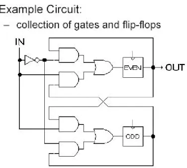
Field Programmable Gate Arrays are two dimensional array of logic blocks and flip-flops with a electrically programmable interconnections between logic blocks.
The interconnections consist of electrically programmable switches which is why FPGA differs from Custom ICs, as Custom IC is programmed using integrated circuit fabrication technology to form metal interconnections between logic blocks.
In an FPGA logic blocks are implemented using multiple level low fanin gates, which gives it a more compact design compared to an implementation with two-level AND-OR logic. FPGA provides its user a way to configure:
1. The intersection between the logic blocks and 2. The function of each logic block.
Logic block of an FPGA can be configured in such a way that it can provide functionality as simple as that of transistor or as complex as that of a microprocessor. It can used to implement different combinations of combinational and sequential logic functions. Logic blocks of an FPGA can be implemented by any of the following:
1. Transistor pairs
2. combinational gates like basic NAND gates or XOR gates 3. n-input Lookup tables
4. Multiplaexers
5. Wide fanin And-OR structure
Figure 11 - Simplified version of FPGA internal architecture
Routing in FPGAs consists of wire segments of varying lengths which can be interconnected via electrically programmable switches. Density of logic block used in an FPGA depends on length and number of wire segments used for routing. Number of segments used for interconnection typically is a tradeoff between density of logic blocks used and amount of area used up for routing.
The ability to reconfigure functionality to be implemented on a chip gives a unique advantage to designer who designs his system on an FPGA It reduces the time to market and significantly reduces the cost of production.
Every FPGA chip is made up of a finite number of predefined resources with programmable interconnects to implement a reconfigurable digital circuit.
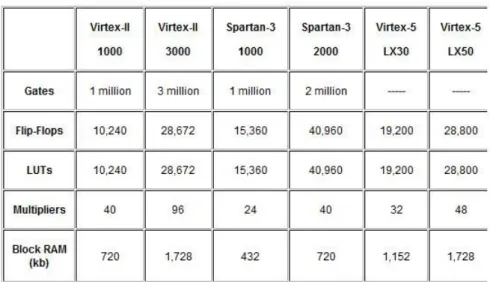
Figure 12 - the different parts of an FPGA
FPGA chip specifications include the amount of configurable logic blocks, the number of fixed function logic blocks, such as multipliers, and size of memory resources like
embedded block RAM. There are many other parts to an FPGA chip, but these are typically the most important when selecting and comparing FPGAs for a particular application.
At the lowest level, configurable blocks of logic, such as slices or logic cells, are made up of two basic things: flip-flops and look-up tables (LUTs). This is important to note because the various FPGA families differ in the way flip-flops and LUTs are packaged together
2.5.2 Why do we need FPGAs?
By the early 1980’s Large scale integrated circuits (LSI) formed the back bone of most of the logic circuits in major systems. Microprocessors, bus/IO controllers, system timers etc were implemented using integrated circuit fabrication technology. Random “glue logic” or interconnects were still required to help connect the large integrated circuits in order to :
• generate global control signals (for resets etc.)
• data signals from one subsystem to another sub system.
• Systems typically consisted of few large scale integrated components and large number of SSI (small scale integrated circuit) and MSI (medium scale integrated circuit) components.
Initial attempt to solve this problem led to development of Custom ICs which were to replace the large amount of interconnect. This reduced system complexity and manufacturing cost, and improved performance. However, custom ICs have their own disadvantages. They are relatively very expensive to develop, and delay introduced for product to market (time to market) because of increased design time. There are two kinds of costs involved in development of Custom ICs:
1. Cost of development and design 2. cost of manufacture
( A tradeoff usually exists between the two costs)
Therefore the custom IC approach was only viable for products with very high volume, and which were not time to market sensitive.
FPGAs were introduced as an alternative to custom ICs for implementing entire system on one chip and to provide flexibility of reprogramability to the user. Introduction of FPGAs resulted in improvement of density relative to discrete SSI/MSI components (within around 10x of custom ICs). Another advantage of FPGAs over Custom ICs is that with the help of computer aided design (CAD) tools circuits could be implemented in a short amount of time (no physical layout process, no mask making, no IC manufacturing)
2.5.3 Logic Block
Logic block in an FPGA can be implemented in ways that differ in number of inputs and outputs, amount of area consumed, complexity of logic functions that it can implement, total number of transistors that it consumes. This section will describe some important implementations of logic blocks.
2.5.3.1 Crosspoint FPGA
Consist of two types of logic blocks. One is transistor pair tiles in which transistor pairs run in parallel lines as shown in figure below:
Figure 14 - Transistor pair tiles in cross-point FPGA
second type of logic blocks are RAM logic which can be used to implement random access memory.
2.5.3.2 Plessey FPGA
Basic building block here is 2-input NAND gate which is connected to each other to implement desired function.
Figure 15 - The Plessey logic block
Both Crosspoint and Plessey are fine grain logic blocks. Fine grain logic blocks have an advantage in high percentage usage of logic blocks but they require large number of wire segments and programmable switches which occupy lot of area.
2.5.3.3 Actel Logic Block
If inputs of a multiplexer are connected to a constant or to a signal, it can be used to implement different logic functions. for example a 2-input multiplexer with inputs a and b, select , will implement function ac + bc´. If b=0 then it will implement ac, and if a=0 it will implement bc´.
Figure 16 - An Actel logic block
Typically an Actel logic block consists of multiple number of multiplexers and logic gates.
2.5.3.4 Xilinx Logic block
In Xilinx logic block Look up table is used to implement any number of different functionality. The input lines go into the input and enable of lookup table. The output of the lookup table gives the result of the logic function that it implements. Lookup table is implemented using SRAM. A k-input logic function is implemented using 2^k * 1 size SRAM. Number of different possible functions for k input LUT is 2^2^k. Advantage of such an architecture is that it supports implementation of so many logic functions, however the disadvantage is unusually large number of memory cells required to implement such a logic block in case number of inputs is large. Fig.14 shows 4-input LUT based implementation of logic block.
Xilinx - LUT based: LUT based design provides for better logic block utilization. A k-input LUT based logic block can be implemented in number of different ways with tradeoff between performance and logic density.
An n-lut can be shown as a direct implementation of a function truth-table. Each of the latch holds the value of the function corresponding to one input combination. For Example: 2-lut shown in figure below implements 2 input AND and OR functions.
Figure 18 - 2-LUT implementation table 2.5.3.5 Altera Logic Block
Altera's logic block has evolved from earlier PLDs. It consists of wide fan in (up to 100 input) AND gates feeding into an OR gate with 3-8 inputs. If floating gate transistor based programmable switch is provide any vertical wire passing near AND gate can be used as input to the AND gate. IF each input signal is present both original and complemented form functional capability of block increases significantly. The advantage of large fan in AND gate based implementation is that few logic blocks can implement the entire functionality thereby reducing the amount of area required by interconnects. On the other hand disadvantage is the low density usage of logic blocks in a design that requires fewer input logic.
Another disadvantage is the use of pull up devices (AND gates) that consume static power. To improve power manufacturers provide low power consuming logic blocks at the expense of delay. Such logic blocks have gates with high Threshold as a result they consume less power. Such logic blocks can be used in non-critical paths.
Altera, Xilinx are coarse grain architecture.
2.5.2.6 Tradeoff - Size of Logic block Vs Performance
Size of logic block plays an important role in deciding density of logic blocks and area utilization in an FPGA. It also effects the performance of the FPGA.
• A large size logic block implements more logic and hence requires less number of logic blocks to implement a functionality on the FPGA. On the other hand a large logic block will consume more space on the FPGA. So optimal size of logic block is one that optimally uses lesser number of logic blocks for functionality implementation while consuming as little space as possible.
• Active logic area is generally less than total logic area due to presence of programmable connections. Total logic area is sum of active logic area and area consumed by programmable connections.
• Routing area in an FPGA is typically more than the active area. It is 70 to 90 percent of total area in an FPGA.
• In case of Lookup table based FPGA, a 4-input lookup table gives best results in terms of logic synthesized and area consumed.
• Granularity of logic block has influence on performance of an FPGA. Typically higher granularity level results in lesser delay between input and output. As the granularity of logic block increases, number of levels of logic in critical path decreases, and hence delay in critical path decreases. On the flip side with increase in granularity level average fan out increases and number of switches also increases as each block has more pins. Also the length of wires increases with increase in size of logic block.
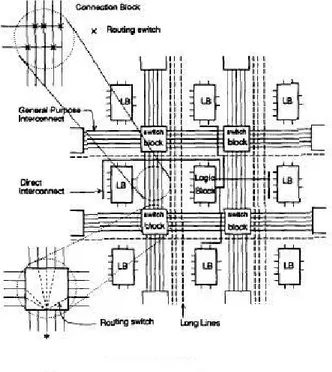
2.5.4 FPGA Routing Techniques
Routing architecture comprises of programmable switches and wires. Routing provides connection between I/O blocks and logic blocks, and between one logic block and another logic block.
The type of routing architecture decides area consumed by routing and density of logic blocks.
Routing technique used in an FPGA largely decides the amount of area used by wire segments and programmable switches as compared to area consumed by logic blocks.
A wire segment can be described as two end points of an interconnect with no programmable switch between them. A sequence of one or more wire segments in an FPGA can be termed as a track.
Typically an FPGA has logic blocks, interconnects and Input/Output blocks. Input Output blocks lie in the periphery of logic blocks and interconnect. Wire segments connect I/O blocks to wire segments through connection blocks. Connection blocks are connected to logic blocks, depending on the design requirement one logic block is connected to another and so on.
2.5.4.1 Xilinx Routing architecture
In Xilinx routing, connections are made from logic block into the channel through a
connection block. As SRAM technology is used to implement Lookup Tables, connection sites are large. A logic block is surrounded by connection blocks on all four sides. They connect logic block pins to wire segments. Pass transistors are used to implement connection for output pins, while use of multiplexers for input pins saves the number of SRAM cells required per pin. The logic block pins connecting to connection blocks can then be connected to any number of wire segments through switching blocks.
There are four types of wire segments available :
• general purpose segments, the ones that pass through switches in the switch block.
• Direct interconnect : ones which connect logic block pins to four surrounding connecting blocks
• long line : high fan out uniform delay connections
• clock lines : clock signal provider which runs all over the chip. 2.5.4.2 Actel routing methodology
Actel's design has more wire segments in horizontal direction than in vertical direction. The input pins connect to all tracks of the channel that is on the same side as the pin. The output pins extend across two channels above the logic block and two channels below it. Output pin can be connected to all 4 channels that it crosses. The switch blocks are distributed throughout the horizontal channels. All vertical tracks can make a connection with every incidental horizontal track. This allows for the flexibility that a horizontal track can switch into a vertical track, thus allowing for horizontal and vertical routing of same wire. The drawback is more switches are required which add up to more capacitive load.
Figure 20 - Actel FPGA routing architecture 2.5.4.3 Altera routing methodology
Altera routing architecture has two level hierarchy. At the first level of the hierarchy, 16 or 32 of the logic blocks are grouped into a Logic Array Block, structure of the LAB is very similar to a traditional PLD. the connection is formed using EPROM- like floating-gate transistors. The channel here is set of wires that run vertically along the length of the FPGA. Tracks are used for four types of connections :
• connections from output of all logic blocks in LAB.