POLITECNICO DI MILANO
School of Architecture Urban Planning Construction Engineering
Master of Science in Building Engineering
Master of Science Thesis:
BIM oriented design for concrete formwork
Comparison between conventional and advanced formwork
systems applied to residential buildings
Supervisor:
Prof. Ing. Marco Lorenzo Trani
Master of Thesis by:
Brillant Uwimana ID. 904247
1
Acknowledgements
I would like to acknowledge different people that have assisted me in the realization of this thesis work and thank the host company Faresin Formwork for the thesis internship opportunity they gave me. In particular, I would like to extend my sincere gratitude and appreciation to my thesis supervisor and my internship supervisor, who guided me and advised me during this research work. I also extend my grateful acknowledgement to my friends, university and internships colleagues who supported me during my academic carrier and all the enterprises for their invaluable cooperation in responding to the questionnaire survey conducted during this research.
Last but not least, I thank God and my family for their love and continuous financial and moral support during my studies.
3
Table of contents
Acknowledgements ... 1 Table of contents ... 3 Abstract ... 5 Sommario ... 6 Table of tables ... 7 Table of figures ... 8 1 Introduction ... 102 Formwork systems state of the art ... 11
3 Literature review ... 12
4 Types of formwork systems ... 16
4.1 Conventional systems (traditional) ... 16
4.1.1 Types and characteristics ... 16
4.1.2 Operational phases analysis ... 19
4.2 Advanced systems (modern) ... 21
4.2.1 Types and characteristics ... 21
4.2.2 Operational phases analysis ... 23
5 Formwork selection criteria’s ... 25
5.1 Regulations and standards overview ... 25
5.1.1 Resistance and stability ... 25
5.1.2 Planarity and surface finish quality... 27
5.1.3 Health and Safety ... 28
5.2 BIM for formwork planning and management ... 29
5.3 Formwork selection based on site management information ... 30
6 Design methodology ... 33
4
6.2 BIM based design methodology ... 34
7 Case studies ... 36
7.1 Introduction to the case studies models ... 36
7.1.1 Wall formwork system: Modulo S100 ... 39
7.1.2 Column formwork system: Poker 100 P100 ... 39
7.1.3 Slab formwork system: Aluflex Slab system ... 40
7.1.4 Conventional formwork systems ... 41
7.2 Used tools and methods ... 44
7.3 BIM library and model creation ... 45
7.4 Design process ... 50
7.5 Results ... 52
7.5.1 Time schedule analysis ... 52
7.5.2 Quantity and cost analysis... 62
7.5.3 Site safety analysis ... 69
8 Conclusion ... 74
9 Future work ... 75
10 Focus on slab systems ... 76
11 References ... 79
12 Annexes ... 82
12.1 Annex I: Time schedules ... 82
12.1 Annex II: Material and labor cost calculation tables ... 88
12.2 Annex III: Questionnaire survey ... 104
5
Abstract
In the residential construction sectors, contractors tend to reduce the costs of the construction phase. It is a logical choice, but this should be done with a long-term vision and putting resource optimization and safety of workers above all. The diffused belief is that advanced formworks are very expensive and should only be used for complex and huge dimension projects. Temporary works especially formwork have seen a lot of innovations in the technology used for the last decade. The same can be said for concrete structures and ultimately it is preferred a lot especially for seismic structures. The trend moved from an operational context in which the construction company decided the nature and methods for the formwork phase to a more advanced and transparent system that privileges the choice of the most appropriate and efficient technologies based on the type of project that is leading to higher productivity, quality and safety. The evolution has also been seen at a regulatory level where in Italy a technical standard has recently been published concerning the production of formwork and their optimal use. The management of the building process in terms of quality and safety is now mandatory. This must be achieved through the planning of works specifically at each individual site. It is therefore necessary to achieve the optimization of the use of formwork and the necessary workforce, to follow simplified and unified construction procedures which are also easily accessible with advanced formwork systems and to consider temporary works as an integral part of the design process and constructive in respect of the quality and safety of workers. For these reasons, taking advantage of the internship opportunity at an italian formwork manufacturer company, the possible advanced technologies applicable in typical small and medium residential buildings were analyzed, through two representative case studies, checking the impact of the choices in relation to time, costs and safety on site. BIM (Building Information Modeling) design technology was used and possible applications in the formwork design and construction process were evaluated. This was possible after the creation of a BIM library that then allowed the BIM modeling of the various building phases for the construction of two residential buildings with two formwork systems in comparison.
6
Sommario
In edilizia residenziale, le imprese costruttive tendono a ridurre il più possibile i costi della fase di costruzione. È una scelta logica, ma ciò dovrebbe avvenire con una visione a lungo termine e soprattutto l'ottimizzazione delle risorse e la sicurezza dei lavoratori. La convinzione diffusa è che le casseforme evolute siano molto costose e dovrebbero essere utilizzate solo per progetti di grandi dimensioni complessità. Le opere provvisionali, in particolare le casseforme, hanno visto tante innovazioni nella tecnologia utilizzata nell'ultimo decennio. Lo stesso si può dire per le strutture in cemento armato che sono sempre più preferite soprattutto per le ragioni dovuti alla resistenza sismica che conferiscono agli edifici. La tendenza è passata da un contesto operativo in cui l'impresa di costruzioni decideva la natura e i metodi impiegati nella fase della cassaforma a un sistema più avanzato e trasparente che privilegia la scelta delle tecnologie più appropriate ed efficienti in base al tipo di progetto che sta portando a una maggiore produttività, qualità e sicurezza. L'evoluzione è stata osservata anche a livello normativo dove in Italia è stato recentemente pubblicato una normativa tecnica relativo alla produzione di casseforme e al loro uso ottimale. La gestione del processo di costruzione in termini di qualità e sicurezza è ora obbligatoria. Ciò deve essere realizzato attraverso la pianificazione di lavori specifici per ogni singolo cantiere. È quindi necessario raggiungere l'ottimizzazione dell'uso delle casseforme e della mano d’opera necessaria, seguire procedure di costruzione semplificate e unificate che sono anche facilmente accessibili con sistemi di casseforme evolute e considerare le opere provvisionali come parte integrante del processo di progettazione e costruttive nel rispetto della qualità e della sicurezza dei lavoratori. Per questi motivi, sfruttando l'opportunità di tirocinio presso un'azienda italiana produttrice di casseforme, sono state analizzate le possibili tecnologie evolute applicabili a tipici edifici residenziali di piccole e medie dimensioni, attraverso due casi di studio rappresentativi, verificando l'impatto delle scelte in termini di tempi, costi e sicurezza in cantiere. È stata utilizzata la tecnologia di progettazione BIM (Building Information Modeling) e sono state valutate le possibili applicazioni nella progettazione della cassaforma e nel processo di costruzione. Ciò è stato possibile dopo la creazione di una libreria BIM che ha poi permesso la modellazione BIM delle varie fasi di costruzione per la realizzazione di due edifici residenziali con due sistemi di cassaforma a confronto.
7
Table of tables
Table 7-1: Work Breakdown Structure of study case 01 ... 52
Table 7-2: Work Breakdown Structure of study case 02 ... 53
Table 7-3: Productivity rates for the main formwork activities ... 56
Table 7-4: Effect of Reuse on Concrete Formwork Cost Based [10] ... 63
Table 7-5: Number of reuses of formwork elements ... 64
Table 7-6: Workers teams hourly costs ... 65
Table 7-7: Labor costs for case 01 ... 66
Table 7-8: Labor costs for case 02 ... 66
Table 7-9: Cost of material and labor per square meter ... 67
Table 7-10: Total cost per square meter ... 67
Table 10-1: Comparison between ALUFORT and ALUFLEX systems... 76
8
Table of figures
Figure 4.1: Wall formwork (Gmb Italy) ... 17
Figure 4.2: Column formwork (Officine Villalta) ... 17
Figure 4.3: Brick-concrete slab (gruppostabila.it) ... 18
Figure 4.4: Brick-concrete slab (CPT Milano) ... 18
Figure 4.5: Positioning of brick concrete slab (Libra Srl) ... 18
Figure 4.6: In slab beam formwork (baroccocostruzioni.com) ... 18
Figure 4.7: composite slab formwork (baroccocostruzioni.com) ... 19
Figure 4.8: Column timber formwork (https://www.youtube.com/watch?v=NYDtWEaSCu4&t=90s) ... 20
Figure 4.9: Plastic formwork ... 22
Figure 4.10: Modular wooden beam formwork ... 22
Figure 4.11: Metal sheathing formwork ... 22
Figure 4.12: Modular metal frame formwork with plywood sheathing ... 22
Figure 5.1: Concrete pressure distribution on the formwork - UNI 11763-1 ... 26
Figure 5.2: Determination of concrete pressure given the pouring speed for tE= 5h - UNI 11763-1 27 Figure 6.1: LOD for overhead handling machinery - tower crane – UNI 11337-4 ... 35
Figure 7.1: Case 01 floor plan ... 38
Figure 7.2: Case 02 floor plan ... 38
Figure 7.3: S100 wall formwork panels - (https://gruppoemac.it/noleggio/casserature/casseforme/casseforme) ... 39
Figure 7.4: S100 wall formwork panels - (https://www.faresinformwork.com/projects/residential/tour-C1/) ... 39
Figure 7.5: Column formwork Poker 100 – (https://www.faresinformwork.com/products/formwork-for-pillars/formwork-for-steel-pillars/) ... 40
Figure 7.6: Aluflex slab system (https://www.faresinformwork.com/products/slab-floor-systems/aluflex/) ... 41
Figure 7.7: Vertical stirrups and steel spacers (Officine Villalta) ... 42
Figure 7.8: Stirrup for column, wedge and complete column formwork (Officine Villalta) ... 42
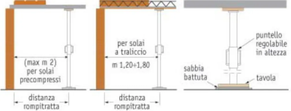
Figure 7.9:Design of the section of timber supports according to the weight of the structure ... 43
Figure 7.10:Design of the prop spacing according to the type of slab joists ... 43
Figure 7.11: Traditional slab formwork - Gruppo Emac ... 43
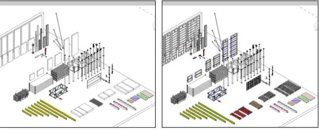
Figure 7.12: BIM library - Advanced system - 2D view ... 47
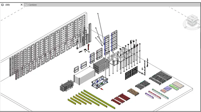
Figure 7.13: BIM library - Advanced system - 3D view ... 47
Figure 7.14: BIM library - Conventional system - 3D view ... 48
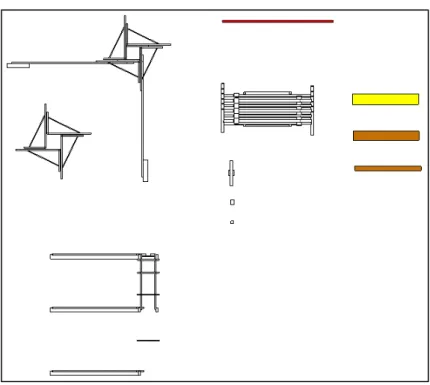
Figure 7.15: BIM library - Conventional system - 2D view ... 48
Figure 7.16: 3D view with LOD B ... 49
9
Figure 7.18: Information contained in wall panel family ... 50
Figure 7.19: Information contained in a slab panel container family ... 50
Figure 7.20: Information contained in a prop family ... 50
Figure 7.21: Mc Leamy curve (by Sanjin Gumbarević) ... 51
Figure 7.22: Case A1 time schedule (Microsoft Project view) ... 57
Figure 7.23: Case C1 time schedule (Microsoft Project view) ... 58
Figure 7.24: Case A2 time schedule (Microsoft Project view) ... 58
Figure 7.25: Case C2 time schedule (Microsoft Project view) ... 59
Figure 7.26:Example of floor plan view of case A1 vertical phase layout ... 61
Figure 7.27: Example of floor plan view of case A1 vertical phase layout ... 61
Figure 7.28: Revit to Excel export Dynamo Script ... 62
Figure 7.29: Comparison of Revit schedule and Excel output table ... 62
Figure 7.30: Alsipercha anti-fall system ... 70
Figure 7.31: Position of the Alsipercha system in case C1 ... 70
Figure 7.32: Walking platform in case A2 ... 70
Figure 7.33: In built safety of Aluflex system case A1 ... 70
Figure 7.34: Safety for vertical formwork case A2 ... 70
Figure 7.35: 4D model from Naviswork - Case A1 (scaffolding are hidden for visualization Unit costrpose) ... 71
Figure 7.36: 360° image produced for virtual reality through QR-code scanning ... 73
Figure 7.37: Screenshots of the VR images from a smartphone after scanning the QR-code ... 73
Figure 10.1: Continuous deck slab system (Alufort) ... 76
Figure 10.2: Grid deck slab system (Aluflex) ... 76
Figure 10.3: (1) prop position on a brick-concrete slab - (2) prop position on a full concrete slab - (3) planking for load distribution. ... 78
10
1
Introduction
Residential construction sector is characterized by a high need of the contractors to reduce the costs of the construction phase by all means. For this reason, construction companies tend to allocate very low resources to the temporary works planning especially the formwork phase. Since timber formworks are made by assembling timber elements on-site [1], the quality of the final work depends completely on the abilities and capacities of the carpenters. Common belief is that advanced formworks are very expensive and are not convenient for small residential building projects [2]. This is mainly because they focus on the high initial cost of the advanced formwork systems only instead of considering the whole process of the concrete structures phase [3]. Construction firms all over the world have been slow to adopt the innovation and changes [3]. One of the long-term problems of traditional timber formwork is their negative impact on the environment; since these systems use a large amount of timber in an inefficient way (large wastage of material) and have short life cycle due to the very low number of reuses [4]. On the other hand advanced formwork systems tend to optimize the use of timber and increase its life cycle by applying protection coating; in this way the number of reuse is increased [5] [6].
Safety is usually an optional especially in residential projects and in most cases it is absent. When laying the floor components for example, it is unfortunately the habit of working at heights without protections in the side areas and in the area below, with the dangers of falling from above. It is therefore essential to plan the sequences of the work phases in detail, to identify the risks and adopt the related preventive and protective measures. Usually the advanced formwork systems tend to be integrated with safety for workers; this facilitates the achievement of safety requirements. This research aim is to identify the advantages of shifting to the advanced formworks for residential buildings construction, in order to help constructors understand the benefits of these systems and adopt them for a more efficient, safe and sustainable concrete phase.
In addition, the thesis deals with the application of Building Information Modeling (BIM) in the ergo-technical design of the formwork phase and its advantages. This is because the BIM methodology is now being used and implemented in many projects for site planning and management. Since formwork systems layout is hugely impacted by the site characteristics and factors such as storage, transportation, assembly or erection are associated with it there is a need of an efficient method of managing these phases. BIM can be a solution since it provides necessary information on materials, site and tools to handle the tasks [7]. Previous studies have shown that BIM formwork layout improves the condition of construction factors like time, safety and sustainability through 3D visualization of constructability, 4D schedules, as-built discrepancies analysis and 5D cost analysis [8].
11
For this thesis two study cases projects were considered and analyzed during a 8 months internship in Faresin Formwork, an Italian formwork manufacturer. Using BIM methodology, the compared formwork systems were applied to both the cases in order to extract all the needed information and quantities for analysis. The design workflow has been analyzed and the advantages of advanced formwork over conventional formwork were investigated as well as the potentials of BIM for formwork design.
2
Formwork systems state of the art
The proper use of formworks as containment elements of other materials could be traced back to the second century B.C. when romans intuited the property of the cement conglomerate mixed with the sand [9]. This concrete was initially used as a filling material but then turned into an independent material suitable for the construction of walls and other structural elements, thanks to its ability to stabilize by solidifying. The concrete is a conglomerate obtained by mixing a hydraulic binder (lime, cement, etc.) and water. Since the arrival of the new way of building that exploits the compatibility between concrete and steel, there has been a development in the use of formwork consisting of planks or wooden panels with supporting substructure in beams and props for support. Over the years, the trend has been moving from systems consisting mostly of wooden boards set up on site without drafting calculations and/or layout drawings to systems specifically designed and composed of subsystems, components and prefabricated elements or made on site.
Formwork can be defined as a temporary structure whose main purpose is to provide support and containment for fresh concrete until it can support itself [10]. Formwork is a mould including all supporting structures, used to shape and support the concrete until it attains enough strength to carry its own weight. Formworks are considered as production factors and represent an essential part of concrete contractor’s work. These must be easy to assemble and disassemble. Cost-effectiveness is guaranteed by the ease of operation, assembly and disassembly of the elements (which must be continuously handled within the construction site). It is also achieved by increasing the number of reuses and reducing the assembly time. The formwork planning and execution process aspects involve:
• the manufacturer, who must place intrinsically safe products on the market, • the designer serving the client or the contractor company, which must choose the
appropriate system of temporary equipment according to the construction procedures needs and methodologies,
• the contractor whose task is to correctly realize on site what the project of the structure prescribes,
12 As for now, concrete is the most widely used material for construction because of its properties of fluidity and resistance [11]. Lately, reinforced concrete is preferred a lot even in residential construction, especially due to the increasingly restrictive seismic standards; therefore, formworks are fundamental in these times since there are no concrete works without formworks.
The formworks constitute a considerable part of the concrete construction cost. It has been estimated to about 30-60% of the total cost of the reinforced concrete works [10] of which around 40-60% is the cost of the material and the rest is labor cost [12]. The formwork manufacturer must therefore not only consider the maximum number of times that any formwork can be reused, but also produce a design that will minimize the time taken for erection and striking, thus reduce labor costs. Among many factors, formwork systems are key factors in determining the success of a building construction project in terms of cost, speed, quality and safety of work. It has been found that, in long run the cost of advanced formwork systems compared to the traditional ones can be optimized by 20% on average [1]. This research focused on the traditional timber formwork system, mostly used in residential buildings in Italy, and its alternative on the advanced formworks side.
3
Literature review
Previous research has focused largely on design of permanent components with minimal attention to temporary works such as formwork for reinforced concrete works and scaffolding especially for small and medium size residential buildings. The following table lists previous studies analyzed during this research. They are divided into three main topics based on their focus: Formwork, BIM and BIM for formwork.
Topic Author Contents
FORMWORK
K. Anitha et al. [1]
They compared merits and demerits of using a
conventional formwork systems and advanced formwork systems in terms of costs, time and quality of these systems for commercial buildings.
B. A. Sida [2] He conducted the study on thirty building projects in Addis
Ababa comparing steel and timber formwork with regarding to cost, quality and time of completion. T. A.
Mohammed et al. [4]
They compared the environmental performance of conventional and advanced formwork systems using questionnaire survey among experts.
A. Tarekegn [6] He assessed formwork construction practices in Ethiopia
13
safety and environmental effects. He then recommended the most suitable systems for Ethiopian constructions. N. A. Haron et al.
[13]
Cost comparison between conventional and industrialized building systems with a focus on formwork systems applied in a four-storey building in Malaysia. C. H. Ko et al.
[14]
They focused on adapting lean manufacturing techniques to formwork engineering in order to reduce waste by
developing a lean formwork construction model that establishes on-site quality control culture and rapid assistance to site problems.
M. S. Rahim et al. [15]
They assessed the cost of formwork systems using data generated from interviews and case study on 260 condominium units.
S. M. Karke et al. [16]
They compared merits and demerits of conventional timber formwork and advanced formwork systems in terms of costs, time and quality of the systems in India.
J. Gambatese et al. [17]
They mapped the life cycle of vertical concrete formwork on three construction sites, identified and evaluated the typical site environmental and operations impacts on formwork during its uses and reuses assessing the impact on structural capacity of formwork and the safety of workers.
R. M. Ghowiba [18]
He developed a model for formwork selection system that is not based on expert’s opinion and can output a purchase cost and detailed quantity take-off with reasonable
accuracy for the selected formwork system. He developed a cost equation and optimization algorithm in order to
compare all the formwork systems while considering all the parameters affecting that selection.
C. Lee et al. [19] After deriving from previous studies on formwork systems
differentiations and factors to be considered for formwork planning, they developed a flow chart and algorithm to apply the factors to formwork layout generation. BIM
K. Sulankivi et al. [20]
This research explores the chances for having 4D BIM as a center technology for site safety related planning activities. They developed procedures and use of BIM technology for
14 safety planning, management and communications, as part of the 4D-construction planning.
S. Azhar et al. [21]
They demonstrated how contractors and sub-contractors can utilize on site BIM technologies for safety planning, management, communication and workers training in real projects.
A. Ganah et al. [22]
They conducted a questionnaire survey to gather information on the embedment of health and safety planning with the BIM environment for site practitioners. M. L. Trani et al.
[23]
In this study, they assessed the efficiency of various BIM tools for site design through several tests finding both their strengths and weaknesses.
A. L. C. Ciribini et al. [24]
They defined a health and safety BIM based design, validation, rule checking workflow with minimum
requirement of site layouts and safety plans using from the Italian construction sites’ health and safety legislative decree law (n°81/2008).
R. Kannan et al. [7] [25]
Using a questionnaire survey on constructability of climbing formwork systems in India in order to compare it with the traditional ones applied on lift core wall of a 20 storey high-rise building using BIM. The comparison concerns cost, time, quality, safety and sustainability factors of both the systems.
BIM for formwork
R. Huang et al. [26]
Using computer simulation techniques, they developed models to study different formwork reuse schemes and assessed their impact on productivity and cost effectiveness using a case study.
M. M. Singh et al. [27]
They explored an approach to reduce the effort expended on formwork design for concrete structures using BIM for quantity take off, scheduling and visualization of
formwork. Z. Jin and J.
Gambatese [28]
They proposed a BIM based tool for planning and designing of formwork through the development of an Application Programming Interface (API) in Revit.
15
Traditional concrete formwork systems have been defined as labor-intensive and time-consuming [26]. K. Anitha et al. found that using advanced formwork systems in commercial buildings can reduce labor requirements by 40% and costs by 20% [1]. The formwork construction activity is often critical and affects the project in terms of time, cost, quality and safety. Findings include the fact that the duration and cost of projects using advanced formwork systems can vary substantially according to the different reuse schemes and the importance of formwork planning has been demonstrated [26]. Data collected through various survey show that one of the reason traditional formwork systems are used is that it allows great short term cost savings and flexibility where labor cost is low and due to their simple manufacturing process [13] [15]. It has been proven that advanced formwork systems provide greater precision and minimize waste in construction, reduce cost and time [1] [4] [16].
After carrying on a market analysis and comparison of formwork systems in India, Patil S. M. et al. recommended that a proper life cycle costing should be performed by contractors to accurately determine whether the advanced formwork system used in building projects will justify the higher initial cost when looked at over the lifespan of the forms [12]. The durability of the formwork in general depends on how it is treated during construction and on the type of material it is made of. If proper care is not given to forms, their number of reuses will decrease [6]. Methods available in literature have been analyzed in order to consider the effect of depreciation on the equipment during the life span [29].
Lee et al. used BIM to provide more specific information about shape, size and structure of buildings than those we can extract from existing 2D drawings [19]. This methodology can help improve productivity (reduced workload) and economic efficiency (reduction of types of formwork and selection of the size of the rational form). Once you have selected the size of the modules and installed the modules outside you can decide whether a weight should be or not taking into account the number of re-uses taking into account the cost and size of the shapes in terms of constructability. However, the exact procedure used for formwork optimization has been not shown. On the other hand, Kannan et al. proposed the use of BIM method to generate a rational formwork layout that includes the real site characteristics. In addition, they paper provided an overview of concepts and techniques required to adopt the BIM as a simplified and interesting tool to carry out 4D Schedule and 5D Cost for the concrete formwork phases [30].
In terms of safety,Gambatese et al. [17] conducted a survey and found that during formwork pouring the most activities associated with workers fatalities are erection and stripping activities and that most high severity accidents occurred during the use of horizontal formwork. It has been found that for commercial buildings the use of advanced formwork systems can reduce accidents by 90%.
16 On the other hand, BIM has proven to be useful for the improvement of health and safety on site. It has been found that BIM improves effectiveness and accuracy in identifying hazards and communicating safety to workers [21] [22]. In addition, falling protection plan can be produced with more details and improvement on site safety planning can be achieved [20].
It can be noted that, studies have been focusing a lot on the formwork systems improvement and comparison between traditional and advanced systems regarding cost, time, quality and safety. However, during the literature analysis, it has been noted a lack of attention to the study of the advantages of advanced systems compared to traditional systems specifically for residential building constructions. For this reason, the thesis tries to carry out that kind of comparison in residential buildings and, the benefits of BIM stated above, applied to formwork phase planning, will be investigated with a focus on construction design and site safety in residential buildings construction.
4
Types of formwork systems
Formwork is defined as a temporary structure whose purpose is to give the desired shape, provide support and containment for fresh concrete until it gains strength to support itself. Formwork system can be defined as the total system of support for freshly placed concrete including the mold or sheathing in direct contact with the concrete as well as supporting members, accessories and necessary bracings [10]. We can distinguish two main types of formwork systems conventional and advanced modular formwork systems. In the following section they will be analyzed focusing on the ones used in residential buildings construction in terms of characteristics and operational phases.
4.1
Conventional systems (traditional)
4.1.1 Types and characteristics
These systems are perceived as the cheapest due to their low initial cost. They allow flexibility since timber can be cut to make any shape. Timber is usually available everywhere and it is very accessible to contractors. Being composed of many small elements assembled on-site, it presents itself as a very light system to move manually. However, the installation of conventional systems requires skilled and experienced carpenters highlighting the potentially huge risk in time, money and materials should the formwork be constructed incorrectly. Just some of the problems that can arise include: material waste due to excessive timber used, failure due to inadequate timber elements used, lengthy construction and dismantling due to inexperience, high unnecessary transport costs, delays, work injuries due to the number of pieces to assemble,… etc. Traditional timber formworks can be classified based on their use (vertical structures or horizontal structures).
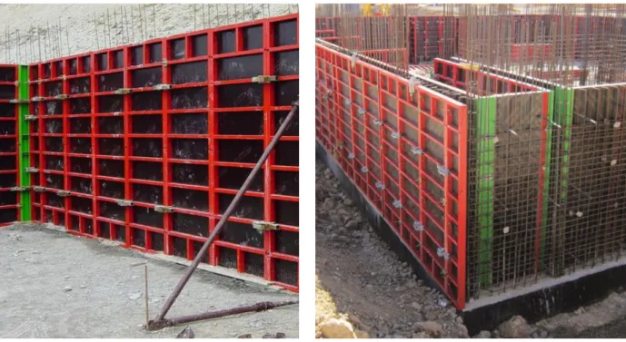
For vertical structures like concrete walls, timber formwork can be made of plywood panels, vertical wooden elements acting as braces, thin metal plates connecting the two faces of the
17
formwork placed horizontally and vertically connected by steel profiles acting as studs. The studs can be single connecting just two consecutive thin plates or continuous connecting more than two thin plates. The thin plates are blocked to the studs using locking wedges. Nails are used to fix the panel to the braces and to fix the thin plates to the panel during the stripping process. For column formwork instead, vertical panels are used usually for the total height of the column and they are positioned to form the column shape. They are tightened together with angular stirrups placed at given intervals and locked in their position with wedges. Timber bracings are used to maintain verticality and resist to lateral loads during the both the pouring phase and the concrete curing phase.
Figure 4.1: Wall formwork(Gmb Italy) Figure 4.2: Column formwork (Officine Villalta)
These panels have a certain number of reuses that can depend on the quality of the finished concrete surface and the frequency of the maintenance made to the panels. They can be reused approximately up to 20 times for high finishing quality and up to 50 times for low finishing quality; in the last case they can easily be used for concrete works where the surface will be covered with a finishing layer. Productivity rate for stripping, dismantling and cleaning the panels is estimated to be 0.40-0.50 h/m². This system is characterized by low level of safety for workers since it is not integrated with safety accessories like walkway brackets and parapets to use during the concrete pouring phase. With this system we can have heights up to 4 m.
18
Figure 4.3:Brick-concrete slab (gruppostabila.it)
Figure 4.4: Brick-concrete slab (CPT Milano)
On the other hand, we have horizontal structures like slabs. In this case we can have many types, but they can be classified in two main groups, concrete plates and composite slabs. Since this research focuses on residential buildings where composite slabs are used, specifically the brick-concrete slabs (Figure 4.4). Brick-brick-concrete slabs have been used since 1903 and they have had an extraordinary diffusion in Italian construction, especially in residential construction [31]. These consist of reinforced concrete longitudinal elements (concrete joists made on site or prefabricated) with mainly structural resistance functions, and lightening elements normally made of brick, simple plastic elements or expanded polystyrene (EPS). For concrete plates, we must have a continuous plywood sheathing surface but in case of brick-concrete slabs we just need supports at given intervals to reduce the span of the concrete joists.
Continuous sheathing must be place only under the beams for the complete concrete pouring. For safety purpose, safety designers can prescribe to contractors the installation of a continuous sheathing even in the brick-concrete slab as the risk of falling is obvious and high (Figure
Figure 4.5: Positioning of brick concrete slab (Libra Srl) Figure 4.6: In slab beam formwork (baroccocostruzioni.com)
19
4.5). This is due to the simple fact that joists are to be positioned alone in first place and void is left in between and if the installation is to be done from above, as it is usually preferred by many in order to speed up the process. In that case all the costs related to that request should be considered safety costs according to the Italian safety decree law [32].
Figure 4.7: composite slab formwork (baroccocostruzioni.com)
In general, the beam (joist) and clay block (brick) slabs consist of structural elements of reinforced concrete (beam) and brick elements with cavities or hollow blocks. The floor is usually completed with a concrete casting to fill the space between the slab components, with the aim of connecting them together and distribute the load between the joists. This structural slab system, in various forms, is widespread in Southern European countries as well as in South America mainly for residential buildings and has many advantages compared to other horizontal structures. In particular, it is very versatile from construction point of view to allow the execution of complex architectural shapes and the articulation of spaces and connections between different parts of the building. The final soffit finish is an easily plastered surface which therefore requires less time and material for the finishing works usually needed in residential buildings.
4.1.2 Operational phases analysis
Common practice for this system consists of sending all the needed materials to the construction site with no design drawings and let the worker (who is an experienced carpenter in the best case scenario) asking him to craft the formwork as quick and as cheap as possible. In this case the carpenter will do everything to the best of his ability but most of the time there is a room for errors since there are not many experienced carpenters nowadays. At the same time there are many
20 planning tasks that could be well carried out in the office in advance by the designers team (like formwork design, drawings for carpenters and material’s site phases and safety planning).
For the vertical concrete formwork, we have the following phases for wall formwork: • Phase 1: frame assembly consisting of an aligner strip and horizontal concrete stop and
vertical braced joist positioned at the joints between panels,
• Phase 2: plywood panels are nailed to the joists; thin plates spacers are placed between the panel,
• Phase 3: vertical steel joists are placed on the external side of the wall and fixed with locking pins,
• Phase 4: the internal side’s panels are subsequently placed and fixed with the help of the previously placed thin plate spacers,
• Phase 5: to conclude, steel studs are placed also on the internal side and fixed with the locking pin.
• Phase 6: bracings are placed to align and support form. Regarding column formwork, the phases are the following:
• Phase 1: positioning of the starting aligner bracket fixed on the floor,
• Phase 2: panels assembly using nails to fix the panels together (the rebars must be placed inside before closing with the fourth side panel),
• Phase 3: the panels are then tied together with steel brackets placed at appropriate intervals according to the concrete pressure distribution; the initial interval is small and increases from the bottom to the top of the column,
• Phase 4: adjacent column formworks are connected if possible and bracings are placed to align and support column form.
21
For horizontal formwork systems, the main phases are:
• Phase 1: positioning of the reference brackets on the column and nailing props to horizontal support on the ground,
• Phase 2: the props and horizontal support are raised, put on the right level and fixed to the reference bracket,
• Phase 3: the props are installed under the stringer (support) at appropriate intervals as specified in the layout design,
• Phase 4: after forming two parallel stringer rows, joists (transversal supports) are positioned at intervals depending on the thickness of the used plywood,
• Phase 5: plywood is then positioned to form a continuous surface for the beam, • Phase 6: positioning of the intermediate supports and its props,
• Phase 7: the intermediate supports are interconnected for bracing,
• Phase 8: lateral stop-end panel positioning and safety elements placement.
4.2
Advanced systems (modern)
4.2.1 Types and characteristics
Industrialized formworks are prefabricated elements and are often made in resistant materials hence reusable many times and as one unit without being disassembled and reassembled for each use. There are many types of industrialized formworks and we can distinguish plastic panel formworks, modular wooden beam formwork, metal sheathing formwork and modular frame formwork for vertical elements. In this study, we will focus on the modular frame formwork type since it is the most used type in residential building. The following images are used to help understand the various cited types.
22
Figure 4.9: Plastic formwork Figure 4.10: Modular wooden beam formwork
Figure 4.11: Metal sheathing formwork Figure 4.12: Modular metal frame formwork with plywood sheathing
Similarly, advanced horizontal formworks are of various types; we can have engineered wooden beam system, aluminum beam system, modular grid systems, aluminum frame panels and all these systems are covered with plywood panels. All these horizontal elements are supported by props at fixed distance s (depending on the system used and the thickness of the slab).
These types of formwork are gaining wide acceptance in the construction market especially for big projects. Since the market is very competitive and speed, efficiency in terms of cost and Productivity are of prime importance as well as high safety requirements, there is a need of adopting standardized elements, easy and quick to install in order to reduce required workers and duration of projects and with long life cycle to reduce impact on project cost.
Panels, beams, supports and often consist of a metal frame and a wooden sheathing. The frame material can be steel or aluminum and the used frame profiles depend on the function of the elements in the frame. The main characteristics of these formwork systems are:
23
• High resistance of elements: since metal frame is used with much strength than wood elements hence less needed materials to achieve great resistance capacity. This permits to reach high concrete pressure load with less deformations and fine tolerance values. Even the sheathing used is optimized for the various purposes in the system,
• High number of use (high durability of materials): The coating of the formwork components makes them more resistant to atmospheric agents and rust for metals. This is especially done to plywood sheathing with protection film that minimize moisture penetration increasing the lifetime. Since during installation formworks are not nailed and for that reason, they maintain their mechanical stability.
• Rapid installation hence savings on labor cost: this is because they are prefabricated and can be pre-assembled to form assemblies easily liftable together to cover bigger area. This is done following a systematic assembly sequence developed to ease and speed the task.
• Integrated safety: the formwork panels arrive on-site ready to receive the service walkways for access stairs, and in general for what is necessary to guarantee safety in all working phases and since they are installed from the ground in a safe position and they come with several accessories easily put in place. Formwork manufacturers always supply along with their products information like assembly and user manuals with safety instructions.
• Smooth surface finishing: the coated plywood used produces smooth and flat concrete finish allowing high levels of flatness.
• Limited wastage of materials: material resources are used intelligently since these formwork systems are industrialized and all the parts and elements are designed and optimized according to the specific function they have in the system.
• High initial investment: this is due to the high quality of material used and the industrialized production process, but the high number of reuses reduces the overall cost and makes them competitive.
4.2.2 Operational phases analysis
In general, the main phases of these systems are almost similar to those seen for the traditional systems with the only difference that in this case nails are reduced to the minimum if not absent, there is no cutting since they are modular and prefabricated and the weight of single elements is greater; for the last reason in order to achieve high Productivity with these systems it necessary to have a crane or other lifting equipment on site.
24 • Phase 1: once defined the modules that can be handled together as one, these have to be
assembled from the ground locked together using aligner clamps,
• Phase 2: the plumbing tubes for vertical stability are fixed on the panels while they are still on the ground
• Phase 3: service brackets are positioned on the panels and the whole system can be lifted to the mounting position using specific lifting hooks,
• Phase 4: consecutive panel modules are fixed together and aligned with clamps to form the desired shape and extension,
• Phase 5: tie rods are positioned with their respective nuts and plastic spacers before the other side of the wall formwork is positioned,
• Phase 6: the sides are tightened together with the nuts and the spacers maintain the desired distance between them.
The column assembly follows the following steps:
• Phase 1: the panels are prepared according to the dimensions needed they are assembled to form an L-shape, fixed together with nuts, and they can be lifted as one to the mounting position.
• Phase 2: after placing the reinforcements, the second L-shape module is positioned and they are fixed together to form the column shape.
• Phase 3: plumbers are used to ensure verticality and bracing, and service brackets can be placed if needed with access ladder.
• Phase 4: in order to reach desired heights module can be added on the top and fixed together with clamps.
Instead for the slab formwork, there are various ways and systems that can be used but the general steps can be the following:
• Phase 1: props with the appropriate heads are placed at given intervals and are temporally stabilized by tripods,
• Phase 2: in some cases, the panels can be placed directly on the prop heads and in others beams have to be placed before placing the slab formwork panels,
• Phase 3: for most systems, braced fields are created in order to ensure lateral stability of the entire system,
• Phase 4: In some cases, the plywood panels are to be positioned after and in others the plywood is pre-assembled with the panel frame.
25
5
Formwork selection criteria’s
5.1
Regulations and standards overview
5.1.1 Resistance and stability
According to the UNI 11763 – 1, the recently published Italian standard for temporary works equipment, in this case for vertical formworks, the formwork and temporary support equipment must be specifically designed for each project, referring to the specific configurations of use envisaged for the construction of reinforced concrete elements. It is up to the contractor to choose the provisional equipment capable of satisfying the prescriptions and requirements of the project specifications as well as the design drawings of the specific formwork and provisional support equipment project. The standard provides general requirements itself for design, assembly and use of the formwork. In addition, it provides a list of technical documentations that must accompany the formwork project in order to make it more comprehensive and informative to the workers. This standard provides methods that must be used to analyze loads applied on the formwork and how to consider concrete pressure on them. It also requires producers to provide the maximum design pression of fresh concrete on the wall formwork; this ensure more safety for the workers and for the project itself since the data is verified even though laboratory test to increase the reliability of the information provided. The respect of this pressure and all the configurations provided must allow the formwork stability in all phases.
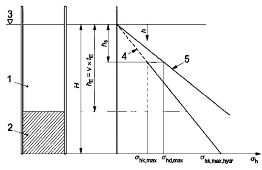
For a long period of time, concrete pressure has been determined based mainly based on the DIN 18218 standard which defined the pressure exerted by the concrete and was derived from the assumption of some boundary conditions like weight of concrete, casting time and temperature, vibration method and casting speed, placed in relation to the six concrete consistency classes of the Eurocode. The new Italian standard provides a method similar to this one for the calculation of the concrete pressure applied on the formworks. It provides diagrams that put into relation the above stated boundary conditions and they are a simple method that can be used for all the verification in all stages by both manufacturers, designers and contractors. The diagram used to determine the concrete pressure distribution is reported below.
26
Figure 5.1: Concrete pressure distribution on the formwork - UNI 11763-1
Where,
1: Hardened concrete 𝜎ℎ𝑑,𝑚𝑎𝑥: Design fresh concrete pressure (kN/m²)
2: Fresh concrete ℎ𝑠: Hydrostatic pressure height (m)
3: Concrete level ℎ𝐸: Fresh concrete height (m)
4: Hydrostatic concrete pressure(𝜎ℎ) 𝑣: Concrete placing rate (m/h)
5: Design concrete pressure(𝜎ℎ𝑑= 𝛾𝐹× 𝜎ℎ) 𝑡𝐸: Setting time - Hardening (h)
𝜎ℎ𝑘,𝑚𝑎𝑥,ℎ𝑦𝑑𝑟: Hydrostatic concrete pressure
(kN/m²)
𝛾𝐹: Safety amplification factor (Action)
𝜎ℎ𝑘,𝑚𝑎𝑥: Maximum fresh concrete pressure
(kN/m²)
Designers or manufactures will prescribe the maximum allowable pressure of the formworks and the contractor will decide the pouring speed based on the diagram provided on the design drawing. Designers can also prescribe the pouring velocity based on the configuration they chose and the work supervisor together with the site safety supervisor, based on the layout drawings, will verify if the contractors are respicting the prescription to ensure safety of worker and avoid any type of failure. Some contractors tend to pour concrete at speeds exceding the allowable in order to increse productivity and so it is important to make the verifications. At this point it is important to say that the big question here is related to the layout drawings for conventional systems; it is very hard to see contractors who provide planning for these systems. The law now requires a
pre-27
construction design before going to site and it is more easy to find this kind of design done for advanced systems even if they are more safe than conventional ones. This said, it becomes more convinient to chose the advanced systems since the design will be for sure done and it will be safer in terms of operational, structural and workers safety. This is even made easy and quick when BIM tools and methodology are used. Having the structural model available, designers can plan every stage of the concrete pouring phse up to the finnest detail in all aspects.
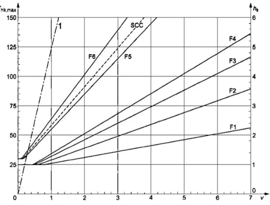
Figure 5.2: Determination of concrete pressure given the pouring speed for tE= 5h - UNI 11763-1
Where,
1: Concrete hydrostatic pressure up to 𝑡𝐸 F1 – F6: Concrete consistency classes
It can be said that fresh concrete pressure depends on the type of concrete and the pouring velocity (defined as average rate of rise of the concrete in the form); formwork systems with high pressure capacity will allow high pouring velocity hence savings in time of the pouring phase with all the related indirect costs and overall time and cost of the concrete works. (especially for vertical formwork).
5.1.2 Planarity and surface finish quality
The surface finish depends on the formwork type used, the characteristics of the concrete, the environmental conditions of the site and the casting methods and procedures. the formwork alone
28 cannot guarantee a surface finish class. The UNI 11763 standard provides indications on how to evaluate the classes related to flatness tolerances of the surfaces of floors, ceilings, and walls. It provides methods based on the DIN 18202 that was mainly used before the publication of the italian standard. The classes achievable by the formwork in given configurations and under specific casting conditions should be specified in the technical specifications made available by the formwork manufacturer. Formwork phase designers can prescribe the desired surface finish classes based on this standard responding to the requests of the structural or architectural designers and the class of use of the building.
5.1.3 Health and Safety
Usually, the choice of the formwork system is solely placed on the contractor. Instead, during the pre-construction phase, designers should be the ones to formulate their own method of construction and coordinate the design of permanent structures with the temporary structures that will be required in order to achieve a more efficient and cost effective construction using methods like geometry optimization.
Designers usually do not give much attention to safety for temporary construction structures and this results in many safety hazards. They are generally not clearly delineated on the building drawings [33]. Since by law [32], all the stakeholders of the construction process, at each level, must ensure the elimination or the maximum reduction of risk factors, for the safety of the workers on site, designers should consider and asses safety and constructability issues early in the project, and how the contractor will build structures safely [34]. Designers and contractors must make responsible choices of the technologies and equipment to be used on site for each project taking into consideration the knowledge and today’s evolution of the techniques in the construction market [32]. These choices will be specified in the Safety Coordination Plan by client designer side (Safety Coordinator) and in the Operational Safety Plan the contractor will specify how he chose to answer to the client’s safety requests through the works operational procedures. It becomes clear that, knowing the potentials of the available technologies and their safety aspects is a must for every participant to the process; this goes especially to those with the possibility and the autonomy of making propositions and choices of which system to be used. Systems integrated with safety must be chosen and the priority must be given to systems offering collective protection instead of those with individual protection [32]. Advanced formworks usually have safety systems integrated and many safety accessories that provide protection to the workers. Research indicated that formwork workers identified erection phase, stripping and assembly as the activities that contribute the most to the cumulative risk in the formwork installation phase. It also indicated that low frequency but with high-severity incidents have the greatest impact on the risk [17]. It has been found that the near miss
29
or collapsing of formwork can be highly avoided in advanced formworks and accidents can be reduced by 90% [1].
5.2
BIM for formwork planning and management
In Italy, Building Information Modeling is now mandatory in public procurement. Starting
from January 2020, BIM is a must for tender amount equal to or greater than € 50 million. This
progressive introduction will go up to 2022 when BIM will become mandatory for all public procurement projects. For this reason, BIM is gaining ground at national level. Abroad, they are also adopting rapidly BIM into national legislations, some countries more than others [35] [36]. The introduction of BIM concerns the whole life cycle of the building construction process. This means that, having building models already available for all the phases and disciplines, we can leverage them as a base to develop the formwork layout for the concrete phase by adding BIM objects and related information. The advantages of this are various as experienced by concrete construction companies that integrated BIM in their process [37]. It permits the accurate planning of formworks, during the preconstruction phase since it is a critical and very time-consuming stage. It also helps in formwork optimization in terms of time and quantity hence reduce costs and respect the project’s budget. AutoCAD tools have been created over the years trying to improve the efficiency of this phase. But, since it was limited to 2D blocks assembled to form a given layout without any information or connection to the intelligent model, errors reduction and optimization could not be achieved [38]. BIM methodology permits the use of time saving design techniques and optimization of the resources since it can be integrated with tools like plugins and other analysis and management tools able to utilize the huge amount of information contained in the BIM families.
Recently Italian BIM standard (UNI 11337) has been published and contains 9 parts up to now. This standard regulates the aspects related to digital management of building information
processes, and the BIM methodology is the way by which to obtain it. In particular, part 4 of the
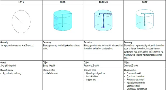
standard is about all the aspects related to the quantity and quality of information content of a digitalized management of the construction process that support the decision-making process. In fact this part establishes the objectives and purposes that must be achieved in terms of information during each phase of the process, in particular by marking the granularity of the information contained in the models through an entirely Italian LOD scale (Level Of Development). As defined by this standard, it is the level of detail and stability of the data and information of the digital objects that make up the models. These can be specified by the employer through the EIR (Employer’s Information Requirements) or agreed between the employer and the supplier. It is clear that this level must be calibrated based on the purpose of the model and its desired uses.
30 BIM has a big role in safety management on construction site. In Australia, It has been identified that there is a distinct lack of BIM objects for temporary construction works resulting in productivity loss during design and construction and the opportunities for improved safety practices with the design and construction of scaffolding and formwork [34]. To prevent site injuries, due to the temporary construction works, there has been considerable interest in improving worksite safety using BIM. Since designers and contractors must, by law, provide clear, complete and adequate information to each person involved in the design and construction process explaining any conditions necessary to ensure that the structure and its execution are without risks to health and safety for workers [32] [34], it is clear that BIM provides the necessary support to meet these requirements.
5.3 Formwork selection based on site management information
During the site design phase, the formwork system must be Unit costt into the site contest and analyzed according to the specific project. In this way the selection is made based on which formwork system is the most suitable for the considered site. It is important, not only to choose the right type of formwork to be used to get the requested results, but to also make sure that there are effective technical, organizational and management skills on-site needed to transform the potential of the chosen system into reality. To understand better formwork site phase management, we can make an analysis based on the six main site product life stages [39] [40]:
• Supply stage: This stage contains the necessary operations to provide the construction site with formwork materials needed to perform the concrete works. It’s about how materials are delivered on site and how they are packed and carried to the site. This includes the size of the vehicle used for delivery, its height and its weight according to the path it will take to arrive on site. It also includes the dimensions and weight of the single packages containing the formworks and their accessories. The other important aspect is about the schedule of the procurement; the site manager has to define when and how much material he will need and how long it takes for it to be delivered on site from the time he orders it; he might select a type of formwork due to its proximity to the site location since usually this implies also the availability of the customer support in case of need. Information regarding procurement (the availability of the product in given areas, the minimum quantity that can be ordered and the delivery time) can be associated to the formwork BIM families to be used in the decision-making phase. During delivery phase, carried materials must be well secured on the vehicle with appropriate accessories so that no damage is caused to the formwork components and to the workers who unload the materials. It is also important to have information on how much pieces are in a package since this will influence the number of handling needed to be carried out manually or by the site crane.
31
• Handling stage: It consists of manual, mechanized and aerial movement operations to be carried out to move materials from one point to the other by means of handling equipment. The lifting machines and capacity available on site: cranes are used for lifting or getting down shuttering materials, iron bars, bricks and other handheld tools etc. which can't be lifted manually to given heights. This stage can be divided into handling form delivery truck to storage, from storage to assembly zone, from assembly zone to installation zone and from installation zone to storage zone after dismantling. Every movement of the formworks and accessories, from the time they arrive on site, is a cost and must be reduced by placing formwork components as close as possible to the place of first use. When handling need to be done manually it is important to choose formwork systems with the lightest components to preserve health of the workers who will handle them as well as to increase productivity. Some formwork systems give the possibility of assembling panels together to move them as one to the installation zone; this must take into consideration the availability of crane or other lifting equipment on site and their load capacity. The more the system can be assembled to form larger parts and cover larger areas the more efficient it will be and the more high lifting capacity will be needed to exploit the system’s potential. Systems with quick and safe hooking devices should be preferred to allow time saving and safety on site and the handling must respect the manufacturer instructions in terms of lifted load and lifting angle.
• Storage stage: This stage consists of the accumulation and the ordered arrangement in appropriate prepared areas of the site, of formwork materials and accessories that arrive on site for the concrete work. This is very important to consider because according to the available space the site manager can decide how much material can be delivered at a time; for this reason, he can choose to use the formwork system that occupies less storage area on site than others. The area must be well limited and protected for the safety of site personnel and the materials must be arranged following supplier’s instructions. The bearing capacity of the storage area must be appropriate for the stored material. Formwork material storage area should be in a position such that it takes less time for workers to access it [41]. Formworks and their accessories should be stored in piles based on their sizes in order to minimize confusion for workers trying to find specific size and reduce waste of time. The packages should be grouped according to concrete schedule to avoid this confusion and the risk of using the wrong size elements. In this stage it is also important to consider the phase in which partially stripped formwork composition can be stored between one mounting phase and another to increase productivity.
• Transformation/assembly stage: This stage consists of assembling single parts to make a unique element or to pre-assemble components before installation. It also includes cutting
32 and joining operations needed to adjust dimensions from standard to personalized. In this stage formwork panels are coated with release oil to prevent concrete sticking on it as it dries. Formwork systems giving the possibility and assemble as much components as possible while being on ground level are preferable because they reduce assembling time since workers move freely and work in comfortable position. They also eliminate the risk of falling from a height being one of the leading causes of fatalities in construction sites [42] [43]. Systems that can be pre-assembled safely from the ground should be preferred for the above benefits. This must be done following producer instructions. Workers must be trained and the assembling area must be properly arranged.
• Installation stage: In this stage formwork elements are placed in their final positions in order to allow the concrete pouring phase to happen with quality and safety for the concrete workers and the future structure. For the vertical formwork, attention it is important to pay attention on the pouring phase where workers are at heights and the concrete pouring tube is in movement. The same for slab formwork systems, the risk increases if the workers have to install the panels from above; in this case protection systems and equipment are needed, and they might result in an increase in costs. Formwork systems that are designed for quick erection and removal facilitating their installation and reducing the need of controls from the workers are to be preferred to those needing instead a lot of care during installation. This helps to reduce time and increase quality and safety with reduced costs. Formwork systems that can be mounted from below or with safety already integrated reduce risks and installation time in this phase.
• Dismantling stage: The last stage comprises all the operations of stripping the formworks after the appropriate maturation time and taking them to the storage area or to the next working area. The maturation time depends strictly on the resistance class of the used concrete. There are some formwork systems that allow the early partial stripping especially for the slab systems. The advantage is that it reduces on-site material requirements; usually deck material can be reduced by half and only the props that must remain in place will be ordered full quantity. This phase includes also the cleaning activity. Choosing formwork easy to clean due to the type of material or treatment of the elements will reduce the duration of this activity. Prior to using the formwork these have to be coated and after the use before taking them off the site the release oil has to be removed; an appropriate area has to arranged on site in order to collect the oil for environmental purpose (protect the aquifer). Another thing to mention is that, during this phase a lot of handling is done manually and sometimes like in case of slabs where we have props in place, horizontal transportation of materials can
33
be a problem for workers; it is important to select systems that allow much spacing between the props or other elements that can be obstacles to workers movements.
6
Design methodology
The construction sector is characterized by a series of constraints deriving from the difficulty of modifying a wealth of rules and construction methods consolidated and shared by all the actors in the construction process. The innovation processes of building production are never presented in a revolutionary form, but rather in the form of slow transformations. In this chapter design method used by formwork phase planners are analyzed to understand the conventional workflow mostly used and the possible workflow using BIM methodology. Formwork design has various objectives. It should provide to designers the clear quantification of the materials and labor needed to complete work and help in the optimization of the layouts and sequencing of the pouring phases to find the perfect balance between quantities, costs and time. It also has to permit the analysis of the right technologies needed to perform all the work phases in operational and functional safety.
6.1 Traditional design method
Design task is generally delegated to the contractors and there is a lack of coordination with the client’s side designers in pre-construction phase. Actually, if design is done, majority of formwork planners use manual process based on Computer-Aided Design and Drafting CADD either 2D or 3D in some cases but limited only to the geometric representation. The method is time consuming since every element is drawn separately for each view and parametric objects are not used and the software used by most designers is line based hence changes are done manually on the views one by one. Quantities extraction is done by selecting elements and through blocks attributes extractions. This technique can present some precision limitations if the elements do not appear in the right views or if elements overlap. The representation is subject to the interpretation ability of the reader of the drawings. This can lead to misinterpretation and ineffective communication especially for safety instruction purpose. In addition, this method does not allow phasing tasks needed to perform concrete pour sequencing. Using 2D elements in form of CAD blocks, with no information associated to them, limits the utility of the drawn elements only to representation. This reduces the possibility to leverage the potential of information processing of the drawn elements. Technical information research is done by hand and can increase design time and slow down the decision making process; whenever designers need to access information related to the elements specifications, installation sequences, delivery to site information, safety instructions and others, they have to analyze user manuals and other documents available provided by the producers. These might be hard to find and maybe not up to date providing incorrect information.