UNIVERSITY
OF TRENTO
DIPARTIMENTO DI INGEGNERIA E SCIENZA DELL’INFORMAZIONE
38123 Povo – Trento (Italy), Via Sommarive 14
http://www.disi.unitn.it
AN EXPERIMENTAL REALIZATION
OF A FULLY-ADAPTIVE SMART ANTENNA
R. Azaro, L. Ioriatti, M. Martinelli, M. Benedetti, and A. Massa
June 2008
An experimental realization
of a fully-adaptive smart antenna
R. Azaro, L. Ioriatti, M. Martinelli, M. Benedetti, and A. MassaDepartment of Information and Communication Technology University of Trento, Via Sommarive 14, 38050 Trento, ITALY
Phone: +39 0461 882057; Fax: +39 0461 882093 E-mail: [email protected]
Key-Terms – Smart antennas, Adaptive Arrays, Antenna Prototype.
Abstract – In this letter, the structure of the prototype of a smart antenna
working in the 2.4 GHz band is described. The radiating structure is composed by a 8-elements linear array with a finite reflecting plane and its adaptive behaviour is obtained by means of a set of electronically-driven vector modulators that control the array weights. The antenna system is equipped with a control software based on a Particle Swarm Optimizer (PSO) algorithm that enables the system to adapt to the complex interference scenario. A selected set of numerical and experimental results are reported and discussed to assess the effectiveness of the proposed architecture.
Introduction
The adaptive control of antennas is one of the most promising solution to interference phenomena and saturation effects that verify in a more and more crowded electromagnetic environment. As a matter of fact, the growing diffusion of mobile devices, which employ wireless standards for data exchange, requires an efficient and complex exploitation of the
communication channels to guarantee a suitable quality of service (QoS). In such a framework, smart antennas [1]-[3] seem to be a very effective tool for the intelligent management of the physical layer since they provide space selectivity functions useful to enhance the signal-to-noise-plus-interference ratio (SINR) at the receiver. The technological difficulties arising in the experimental realization of fully-adaptive antenna systems [4] prevented their development and successive application in wireless systems. Consequently, simpler architectures, as reconfigurable [5][6] or switched-beam antennas [3], have been proposed and implemented. In this letter, the design of a prototype of a fully-adaptive antenna is described and validated through some representative numerical and experimental results.
Structure of the Fully-Adaptive Antenna
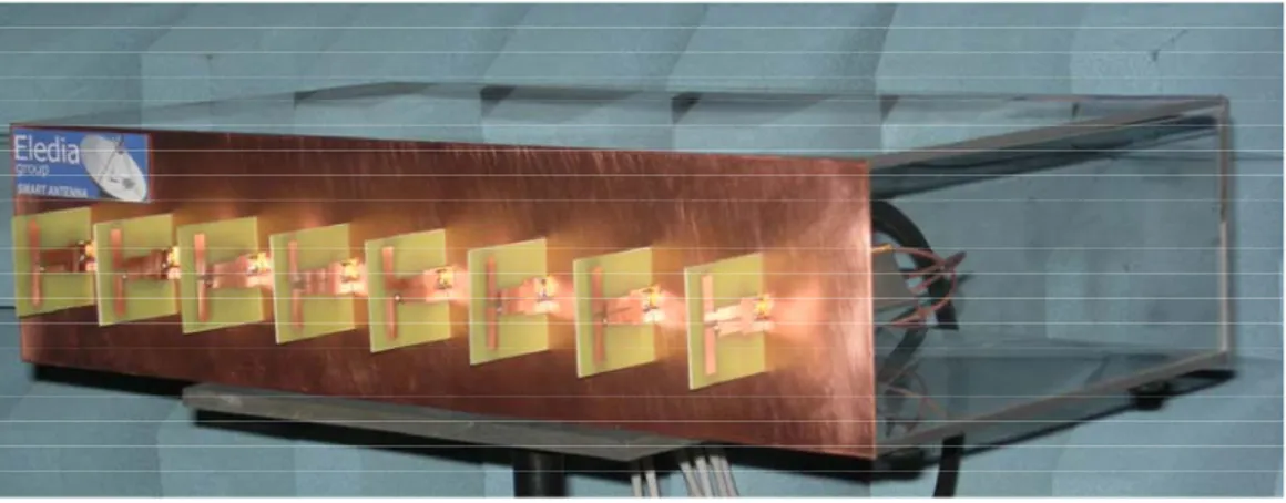
With reference to Fig. 1, the fully-adaptive antenna is composed by 4 different modules that provide the system with the necessary hardware and software functionalities: (a) the radiating module, (b) the HW control module, (c) the combiner of the RF signals, and (d) the software control module. More in detail, the radiating system is composed by a linear array of 8 equally-spaced
(d=λ02 ,
0
λ being the free-space wavelength at 2.4 GHz) elements and a
finite reflecting plane of extension 9λ0× parallel to the array at a distance of λ0
4 0
λ (Fig. 2). The dipoles equipped with integrated baluns have been
designed according to the guidelines given in [7] and printed on a dielectric substrate. A vector modulator working in the 2.4 frequency band has been used to introduce an attenuation in the range (-4.5 ÷ -34.5) dB and a phase
delay from 0 up to 360° with a value determined by a couple of low frequency differential voltages (-500 ÷ 500 mV). The outputs of the control module are then grouped in a passive RF power combiner (8 way, 0°), built on an Arlon dielectric substrate, which employs 7 microstrip Wilkinson power combiners. The combined signal is then processed by a spectrum analyzer that emulates a receiver able to estimate the SINR value. The whole system is controlled by a personal computer hosting the PSO-based software control. Starting from the current status of the system (i.e., the SINR value) and according to the particle swarm evolution strategy [8][9], such a module defines the array coefficients to maximize the SINR. Thus, the radiation pattern of the system is continuously modified by placing a maximum value of attenuation in the direction of arrival (DoA) of the interference signals. As far as the hardware interfaces are concerned, there is a GPIB interface between the PC and the spectrum analyser. Moreover, a digital to analog I/O interface has been used to drive the vector modulator with the required differential voltages. Finally, in order to avoid/minimize the electromagnetic interferences between the radiating elements and other HW components, the modules (a) and (b) have been placed just behind the rectangular reflecting surface (see Fig. 2) to shield the array elements and the RF modules.
Numerical and Experimental Results
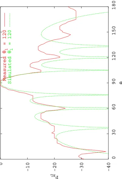
Both hardware and software modules have been separately tested and then integrated to assess the adaptive behaviour of the antenna system. The preliminary assessment has been aimed at verify whether the system is able to control the angular positions of the attenuation maxima in the radiation
pattern. Towards this end, an exemplificative interference scenario
characterized by a jamming signal coming from θ1= 120° and the desired
signal impinging at θdes = 0° has been considered. Figure 3 resumes the
obtained results in terms of radiation patterns. Both simulated and measured quantities are reported. As it can be noticed, the system prototype is able to
place a minimum of the beam pattern at θ1= 120° and, at the same time, to
maintain the main beam oriented along the DoA of the desired signal
(θdes = 0°).
Conclusions
In this letter, the prototype of a smart antenna composed by a 8-elements linear array with a finite reflecting plane and working in the 2.4 GHz band has been described. A selected set of preliminary numerical and experimental results have reported to assess the effectiveness of the proposed architecture in shaping the antenna beam pattern to maximize the reception performance of the system.
Acknowledgments
This work has been partially supported in Italy by the “Progettazione di un Livello Fisico ‘Intelligente’ per Reti Mobili ad Elevata Riconfigurabilità,” Progetto di Ricerca di Interesse Nazionale – MIUR Project COFIN 2005099984.
References
1 R. H. Roy, An overview of smart antenna technologies and its application in wireless communication systems, Proc. IEEE Conf.
Personal Wireless Comm., Mumbai, (1997), 234-238.
2 S. Bellofiore, C. A. Balanis, J. Foutz, and A. S., Spanias, Smart antenna systems for mobile communication networks. Part 1: overview and antenna design, IEEE Antennas Propagat. Mag. 44 (2002), 145-154. 3 S. Bellofiore, C. A. Balanis, J. Foutz, and A. S., Spanias, Smart antenna
systems for mobile communication networks. Part 2: beamforming and network throughput, IEEE Antennas Propagat. Mag. 44 (2002), 106-114. 4 S. P. Applebaum, Adaptive arrays, IEEE Trans. Antennas Propagat. 24,
(1976), 585-598.
5 M. D. Migliore, D. Pinchera, and F. Schettino, A simple and robust adaptive parasitic antenna, IEEE Trans. Antennas Propagat. 53 (2005), 3262-3272.
6 L. Petit, L. Dussopt, and J. M. Laheurte, MEMS-switched parasitic-antenna array for radiation pattern diversity, IEEE Trans. Antennas
Propagat. 54 (2006), 2624-2631.
7 H. R. Chuang and L. C. Kuo, 3-D FDTD design analysis of a 2.4-GHz polarization-diversity printed dipole antenna with integrated balun and polarization-switching circuit for WLAN and wireless communication applications, IEEE Trans. Microwave Theory Techn. 51 (2003), 374-381. 8 M. Benedetti, R. Azaro, D. Franceschini, and A. Massa, PSO-based
real-time control of planar uniform circular arrays, IEEE Antennas Wireless
Propag. Lett. 5 (2006), 545-548.
9 J. Robinson and Y. Rahmat-Samii, Particle swarm optimization in electromagnetics, IEEE Trans. Antennas Propagat. 52 (2004), 397-407.
Figure captions:
Fig. 1 Fully-adaptive antenna architecture
Fig. 2 Photograph of the prototype of the fully-adaptive antenna
Fig. 3 Radiation pattern of the fully-adaptive antenna when θdes = 0° and ° = 120 1 θ : ——— measured - - - simulated
IEEE 488.2 90° 90° 90° Vector Modulators Radiating Elements (c) Module Combiner (b) Module HW Control (a) Module Radiating (d) Module SW Control (NI−6723)
PSO Array Control
PC Interface Digital I/O Interface GPIB (Agilent ESA−E4404) Spectrum Analyzer ∆ϕ= ∆ϕ= ∆ϕ= RF Power Splitter/Combiner (8:1)
-40 -30 -20 -10 0 0 30 60 90 120 150 180 P RL θ Measured θ1 = 120 Simulated θ1 = 120