U
N
F
II
School of Polytechnic and Basic Sciences
Department of Chemical, Materials and Industrial Production Engineering
XXXI PhD Programme in
Industrial Products and Processes Engineering
Study of thermoplastic composite joining
technology by electromagnetic induction heating
PhD COURSE COORDINATOR
PhD CANDIDATE
Ch.mo Prof. Ing. Giuseppe Mensitieri
Ing. Barbara Palmieri
PhD SUPERVISOR
III
Acknowledgement
I would like to thank my supervisor, Professor Luigi Nele, because without his guidance, encouragement and patience I could have never obtained these results. I wish to thank him for his help and advice during my period of research.
I would also express here my acknowledgments to Dr. Francesco Galise, researcher at Fiat Research Center, who always supported me during my PhD programme. I would like to thank him for his precious knowledge contribution and for the technical support.
1
Table of contents
Acknowledgement ... III
Table of contents ... 1
List of Figure ... 4
List of Table ... 8
Abstract ... 9
Introduction ... 10
Introduction ...10 Objective ...12 Approach ...13State of the Art ... 14
Induction Heating ...14
2.1.1. Estimation of the generated Power ...15
2.1.2. Susceptorless Induction Heating ...16
2.1.3. Heating Mechanism in Susceptorless Induction Heating ...18
2.1.4. Influence of Induction Coil Geometry ...21
2.1.5. Skin effect ...22 2.1.6. Edge Effect ...23 Fusion Bonding ...24 2.2.1. Ultrasonic Heating ...30 2.2.2. Resistance Heating ...32 2.2.3. Induction Heating ...33
2
Modelling of Induction Heating ...35
Electromagnetic Heating for Adhesive Bonding ... 38
Introduction ...38
Three-Dimensional Finite Element Model ...41
3.2.1. Materials ...46
3.2.2. Geometry and Mesh ...46
Induction Heating Bonding Experiments ...47
3.3.1. Materials ...47
3.3.2. Specimens ...48
3.3.3. Experimental set-up ...49
Results and discussion ...53
3.4.1. Correlation ...55
3.4.2. Joint Performances ...56
3.4.3. Analysis of Variance ...60
Conclusions ...64
Effect of Current Frequency ... 65
Introduction ...65
Three-Dimensional Finite Element Model ...69
4.2.1. Material Properties ...71
4.2.2. Boundary Conditions ...72
4.2.3. Geometry and Mesh ...73
Induction Heating Experiments ...76
3
4.3.2. Experimental Setup ...76
Results and Discussion ...82
4.4.1. Influence of frequency ...84
Conclusions ...94
Future works and perspective ... 96
Conclusion ... 101
4
List of Figure
Figure 1: Volume resistivity (Ohm/cm) [19]...16
Figure 2: Heating Mechanisms of carbon fibre reinforced polymer composites 18 Figure 3: Fibre Heating as Intrinsic Heating ...19
Figure 4: Junction Heating-Dielectric Heating ...20
Figure 5: Fibre junction heating- contact resistance ...20
Figure 6: Edge Effect in induction heating ...24
Figure 7: Categorization of fusion bonding techniques by the heating mechanism ...26
Figure 8: Scheme of two surfaces in contact [38] ...28
Figure 9: USW schematic for lap joint (a), zoom of the joint (b) ...30
Figure 10: Energy directors ...31
Figure 11: Schematic Induction heating ...33
Figure 12: Relation between physical phenomenon and analysis model ...41
Figure 13: Pattern of the model ...42
Figure 14: Electrical circuit scheme ...43
Figure 15: Current values set for the case of the current value of 24 A ...44
Figure 16: a) CAD Model of ASTM standard D2344; b) CAD Model of ASTM standard D5868 ...46
5
Figure 18: Configuration and dimensions for the standard methods: a) ASTM
D2344 and b) ASTM D5868 ...49
Figure 19: Coil's shape and dimensions ...51
Figure 20: Experimental Set-up ...52
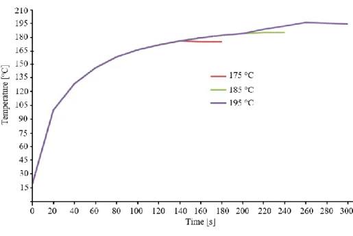
Figure 21: Profile temperature ...53
Figure 22: Temperature field at holding time at t=0s (a) and t=30s (b). ...54
Figure 23: Temperature field of Ertalon's support ...54
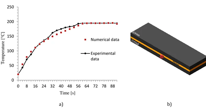
Figure 24: a) Comparison of the numerical and experimental temperatures. b) The reported surface is controlled using an optical pyrometer and is the set point adopted for the control of the induction bonding equipment. ...55
Figure 25: Temperature distribution into the adhesive layer: a) D2344 and b) D5868 for the same process parameters: I3, T2 and t2. ...58
Figure 26: Example of the fracture surface of a tested specimen realised according to D2344: a) adherends failure and b) failure at the adhesive-adherends interface ...59
Figure 27: Example of the fracture surface of a tested specimen realised according to D5868: a) cohesive failure, about 88% and b) adhesive failure, about 70% ...60
Figure 28: Interval Plot of Average D2344 ...61
Figure 29: Interval Plot of Average D5868 ...61
Figure 30: Main Effects Plot for D2344 results...63
Figure 31: Main Effects Plot for D5868 results...63
6
Figure 33: (a) Geometry of the FE model, with the composite laminate, ceramic
support and coil and mesh generated (b) ...75
Figure 34: Egma 30R generator panel control...77
Figure 35: Geometry of the coil used ...78
Figure 36: Experimental set-up for induction heating of CF/PPS ...79
Figure 37: Geometry of the Coil, realised to obtain the frequency of 130 kHz (a) and 150 kHz (b) ...81
Figure 38: Heating patterns of the surface of CF/PPS laminate ...82
Figure 39: Correlation between simulated temperature maps (a) and thermal camera image (b) at the heated surface coil current 20 A and frequency 200 kHz. ...83
Figure 40: Evolution of temperature for the CF/PPS during heating at 200 kHz and values of current from 10 to 30 A: comparison between simulated, N, and experimentally, E, measured values. ...84
Figure 41: Iso-power curve obtained by the numerical model ...84
Figure 42: A-scan of an unheated specimen ...86
Figure 43: Image of the measurement point for the NDI tests. ...87
Figure 44: A scan of samples heated at iso-power of 97 kW with 130 kHz and 15 (a), 150 kHz and 13 A (b) and 200 kHz and 10 A (c). ...88
Figure 45: A scan of samples heated at iso-power of 135 kW with 130 kHz and 22 (a), 150 kHz and 20 A (b) and 200 kHz and 15 A (c). ...89
Figure 46: A scan of samples heated at iso-power of 162 kW with 130 kHz and 27 (a), 150 kHz and 25 A (b) and 200 kHz and 20 A (c). ...90
7
Figure 47: Temperature-Time Diagram for the samples heated at 150 kHz 20 A
and 200 kHz 15A ...91
Figure 48: Temperature-Time Diagram for the samples heated at 150 kHz 25 A and 200 kHz 20 A. ...92
Figure 49: Capacitor scheme of the laminate ...93
Figure 50: New coil designed for the next experimental campaign. ...96
Figure 51: 3D Model of the conic shape coil ...97
Figure 52: Mesh realised for the conic coil simulation ...97
Figure 53: Temperature distribution of the conic coil ...98
Figure 54: Geometry of the coil with only the spires ...98
Figure 55: Temperature Distribution of the coil with the only spires. ...99
Figure 56: Heating distribution generated by the circular coil (a) and the new conical coil realised (b). ... 100
8
List of Table
Table 1: Input parameters of the FE model for CFRP, Ertalon’s support and Prodas
...46
Table 2: Summary of all simulations performed...50
Table 3: Results of the mechanical tests according to ASTM D2344 and ASTM D5868 for all the experiments performed ...56
Table 4: Maximum values of shear strength for the testing methods ASTM D2344 and ASTM D5868 for induction heated and Reference samples. ...57
Table 5: Input parameters of the FE model ...72
Table 6: Electrical Properties of Copper and air ...72
Table 7: Summary of the values of the frequencies and current imposed ...73
Table 8: Values of the frequency and the current for induction heating in the iso-power regime ...85
9
Abstract
The development of light structures in the transport field is closely related to the development of manufacturing and processing technologies. The thermoplastic matrix composite materials are very interesting also for the possibility of hot forming by deformation, and their use is continually increasing. Moreover, these materials allow the possibility of performing welded joints of the parts. The automotive industry and aerospace industry seem to be the industrial sectors that have the most significant potential for application of thermoplastic composite materials.
The joining of thermoplastic composites could be carried out using hot melt adhesives or with fusion welding of the thermoplastic matrix.
The heating of a hot melt adhesive, or the thermoplastic matrix could be carried out with electromagnetic induction technology.
This PhD thesis deals with the electromagnetic induction heating of thermoplastic matrix composite materials for adhesive bonding, and also study for the first time the influence of the current frequency on the heat penetration depth.
A numerical model was developed using two different Multiphysics Software, such as Jmag and COMSOL; then the models were validated using an experimental campaign.
The main original result of the work is that in the case of thermoplastic matrix composites, the higher the current frequency the higher is the depth of the heat penetration, unlike the case of the metal alloys.
10
Introduction
Introduction
The development of ever lighter and with high specific mechanical properties structures, at lower costs, is a crucial factor in the transport industry, mainly as to the automotive industry.
The quickest way to improve operational efficiency is the use of structural and semi-structural lightweight materials including advanced metals (high-strength steel, aluminium alloy) and continuous fibre-reinforced composites materials. The number of applications that require the use of thermoplastic matrix composites has increased considerably in the last years, due to their mechanical characteristic and their rapid and low-cost processing and manufacturing [1]; moreover, thermoplastic matrix composites (TPC) of more recent development have mechanical properties comparable to those of thermoset composite or even better [2].
The ideal solution would be to build a structure without joints, these being a potential source of weakness and extra weight.
However, in many practical applications, it is virtually impossible to create an entire structure in one piece, both because of the high costs, which this would imply, and both because of problems associated with the geometrical limitations. Different benefits of maintenance, accessibility, repair, transport or assembly show that the joints play an essential role in an engineering structure.
This aspect is particularly evident in the manufacture of composites, where the high viscosity of the molten resin and the constraints imposed by the presence of reinforcements limit the production components at relatively simple geometry which must then be joined together to form more complex structures [3, 4]. The joining of the various component is a critical step in the manufacturing process of TPCs products because it could introduce some irregularities in the structure that can result in weakening of the properties [5].
Traditional joining technologies, such as mechanical fastening, are not directly transferable to composites [6]; consequently, the joining techniques, alternatives
11
to the classic mechanical joints, are extremely interesting for these types of materials.
A composite laminate is formed by joining itself more laminae on each other, and the use of mechanical joints in the realisation of composite structures involves several problems such as:
- stress concentrations around holes; [7]
- possible delamination caused by drilling operations [8];
- temperature induced stresses caused by the different thermal expansion coefficient of composites and fasteners [9].
- the possible presence of galvanic corrosions at joints [8].
The continuous joining techniques, such as welding, and bonding are preferred over discontinuous joining techniques, or mechanical.
During the lifecycle of composite materials, a heat source is often necessary. It is generally provided by thermal transfer from the material’s outer surface (heat transfer, autoclave, etc.). These processes are characterised by high cycle time since heat needs time to propagate in the volume of the material.
Additionally, the cycle time depends only on the material’s physical properties and geometry and is not controllable by the heating process. These involve productivity losses.
Induction is an alternative technique to supply heat directly the composite material if the reinforce is an electrical conductor.
The main advantages of induction are the following:
- Core or surface heating, based on the generator’s frequency; - Lack of contact allowing dynamic elaboration;
- Global or localised heating; - High transmitted power density;
12
Objective
Due to the complex nature of the induction heating process and processing condition a large process design, based on experimental works, is necessary. This is expensive and time-consuming. For this reason, modelling can be a good way for a better understanding of the process characteristic and improving the process design of induction welding.
Three-dimensional models could be useful to predict the spatial temperature distribution, during the entire fusion bonding process. Additionally, coil design, that is a fundamental aspect for this kind of application can also be improved. Moreover, process optimisation and assessment of the significance of the parameters involved in the process can be achieved fast and in a very cost-efficient way.
The objectives of this study are:
1. Study the heating behaviour of high-performance carbon fibre reinforced thermoplastic composites;
2. Development a coupled electromagnetic and thermal finite element models of the induction heating process, applicable both for the adhesive bonding and for welding;
3. Analysis of the role of the process parameter for the application of the induction heating, focusing in particular on the current frequency.
13
Approach
In the following, the approach to the work is shown.
Chapter 2 summarises state of the art in induction heating of carbon fibre reinforced thermoplastic polymers. Selected aspects relevant to the objectives above are discussed, starting from the basics of the fusion bonding process and induction heating. Furthermore, fundamentals for modelling the process, focusing on the heating step, are presented.
Chapter 3 contains the part dedicated to the application of the electromagnetic induction heating for the adhesive bonding of thermoplastic composites. The numerical model developed, using JMag software was explained. Then materials and experimental procedures used for induction heating and bonding experiments, respectively, are illustrated. Additionally, the results of the mechanical tests performed are reported and are analysed.
In Chapter 4 the induction heating of thermoplastic composites was studied. Also, in this case, a numerical model was developed, with a different software, COMSOL Multiphysics, with the aim to assess the influence of the process parameters on heating. Moreover, the influence of the current frequency on the depth of heat penetration through the thickness was for the first time studied, keeping the power constant. The numerical model has been verified with experimental tests. The influence of current frequency was investigated using the different ultrasound energy absorption of the amorphous or semi-crystalline structure of the thermoplastic matrix: the study has highlighted that as the current frequency increases, heat penetration in the thickness of the material, at the same power supply, increases, unlike the case of metal alloys.
Chapter 5 summarises the main achievements of this work and gives suggestions for further development of the induction heating process, reporting the new results obtained changing the coil shape. Additionally, a new improved shape coil has been realized.
14
State of the Art
Induction Heating
Induction heating is a contactless heating process used to heat an electrically conductive or ferromagnetic material through electromagnetic induction. This technology is widely used in industry, and the underlying physics is widely described [10].
The electromagnetic induction’s basic principle was described by English physicist Michael Faraday [11] in 1830 during a laboratory experiment, later Heinrich Lenz and J. Henry gave essential contributions on this research, and finally, C. Maxwell [12] evaluated the equations mathematically for electromagnetic phenomena.
When an alternating voltage is applied to an induction coil, resulting in an alternating current in the coil circuit, a time variable electromagnetic field in coil surrounding is generated. The alternating electromagnetic field generated has the same frequency as the coil current. If the adjacent material is conductive, the electromagnetic field induces eddy currents; instead, if the material is ferromagnetic, the electromagnetic field creates magnetic polarisation. In case of material characterised by a dual nature, both conductive and ferromagnetic, a combined effect may take place; heating can be obtained by Joule losses and magnetic polarisation effect respectively [13]. Conductive materials generate heat due to Joule effect and ferromagnetic materials by magnetic hysteresis loss, thanks to the friction of magnetic dipoles [14].
In conductive fibres filled composites heating occurs due to induced eddy currents flowing along conductive loops, and in each conductive loop, a drop-in voltage occurs due to the electrical impedance. This volumetric heat generation depends on intrinsic properties of the composite.
Heating of carbon fibre reinforced thermoplastic composites is a very complex phenomenon due to different mechanisms of heating generation [15].
15
Due to this complexity, the current distribution is non-uniform within the inductor and the workpiece, resulting in a non-uniform distribution in the workpiece [10].
2.1.1. Estimation of the generated Power
A coil connected to an alternating voltage will carry an alternating current in the coil that produces a time-variable magnetic field of the same frequency in its surrounding [10].
The power P generated during the induction heating can be evaluated only from numerical computations. The power depends on the surface power density and the workpiece surface exposed to the magnetic field, an approximation is given by the equation (1)
𝑃 =4𝜋
2∙ 𝑓2 ∙ 𝜇2∙ 𝐻2∙ 𝐴2
𝑅 (1)
Where P is surface power density, H is magnetic field intensity at the surface, A is the area of the surface, 𝝁 is relative magnetic permeability at the surface, R is electrical resistivity, and 𝒇 is frequency.
The magnetic field intensity 𝑯 of a current carrying a thin conductor can be calculated with the Bio-Savart law, is given by:
𝐻 = 𝑖 4𝜋∙ ∫ 1 |𝑟⃗|2∙ ⌊𝑑𝑙⃗ × ( 𝑟⃗ |𝑟⃗|) ⌋ (2)
Where 𝒊 is the coil current, 𝒅𝒍 a section of the coil length, and 𝒓 is the distance between the coil and some point p [16].
Then, to perform iso-power analysis and experiments, it is necessary to vary the values of the current and the frequency; in particular, increasing the frequency must decrease the current and vice versa.
16
2.1.2. Susceptorless Induction Heating
Materials can be classified as insulator and conductors basing on their resistivity. Polymeric materials are characterised by high resistivity and act as insulators, while metals have very low resistivity, and act as conductors. Some fillers can be introduced in polymers to reduce their resistivity. The intrinsic conductivity of fillers, their aspect ratio, interactions between polymer and filler surface, their distribution and orientation are critical parameters to obtain the conductivity and their percolation threshold [17, 18].
Figure 1: Volume resistivity (Ohm/cm) [19]
Figure 1 shows the volume resistivity of various materials. Unfilled polymers are insulation, and as the filler concentration increases, resistivity decreases. Electrostatic discharge (ESD), electromagnetic interference (EMI) and radiofrequency interference (RFI) shielding also need electrically conductive materials. Finally, pure metal has very low resistivity. The electrical conductivity of composites depends on the intrinsic conductivity of polymer and fillers. Polymers have very low electrical conductivities in the range of 10-14 to 10-17
17
black has a conductivity of 102 S/cm, graphite 105 S/cm and pitch-based carbon
fibres have 103 S/cm [20, 21].
Usually, neat polymers cannot be heated by electromagnetic induction because they are neither electrically conductive nor electromagnetic. So, it is necessary to apply susceptors to convert the magnetic energy into thermal energy. Susceptor generally are in form of particles [22, 23], metallic [24, 25] or carbon fibre fabric [26, 27]. The presence of susceptors can introduce stress concentrations and lower the possible strength [28]. Ahmed et al. [29] have defined the term “susceptorless induction heating”; in this case, the workpiece already consists of a type of material, like carbon fibre fabric reinforcement, which enables induction heating to occur. Carbon fibres are electrically conductive, so they can be used as heating element [15, 16, 30–32], though this causes the heating of the whole composite [7].
In carbon fibre reinforced materials, the fundamental conditions for the generation of eddy currents are the formation of closed electrical loops as demonstrated in the works of Miller et al. [30] and then later by Fink et al. [27]. To obtain the electrical loops in the composite is primary to use fibres in woven form; electromagnetic induction cannot be applied for the heating of unidirectional laminates.
Additionally, Miller et al. [30] have shown that the eddy currents induced in the workpiece are a mirror image of the coil [29]. Consequently, the current produces its magnetic field which nullifies the magnetic field in the deeper regions of the material. The extension of this nullification depends on the intensity of the induced current on the surface closest to the inductor. The current can only flow through a conductive electric field, or along the conductive fibres. An image more like the coil shape has appeared in the fabrics, probably due to the high incidence of the electrical contacts within the fabric [15].
18
2.1.3. Heating Mechanism in Susceptorless Induction Heating
As reported by Bayerl et al. [33], three mechanisms co-occur for volumetric heating in conductive fibre fabrics: (i) heating by Joule losses along the fibres, (ii) dielectric heating at fibre junctions [27] and (ii) heating by contact resistance at junctions [15]. The first (i) occurs along the carbon fibres, the latest ones at fibre crossover junctions, as shown in Figure 2.
Figure 2: Heating Mechanisms of carbon fibre reinforced polymer composites
Fibre Heating
The fibres heating is the result of losses for Joule effect due to the internal resistance of the fibre.
The induction parameters and reinforcement architecture determine the amount of Joule heating in the conductive fibre; electrical resistance (𝑹𝒇) and heat generation (Pf) are dependent on the cross-sectional area (Af), fibre resistivity
(𝝆𝒇), and length (lf), as reported by the (3) and Figure 3. 𝑅𝑓 = 𝜌𝑓
𝑙𝑓
19
Figure 3: Fibre Heating as Intrinsic Heating
Junction heating
Junction heating occurs at the fibre junctions, and it dominates when the carbon fibres are not in good contact (contact resistance > 103- 104 [15]).
Dielectric heating at fibre junctions occurs when applying an alternating electric field, a potential difference is created between the fibres, which, being separated by a thin matrix layer, act as a capacitor [15, 27]. The dielectric heating can be modelled as a conductive circuit with a resistor (Rhd) and a capacitor (Chd) in
parallel.
The resistance between the fibres can be calculated as: 𝑅𝑑ℎ =
ℎ
𝜔𝑒0𝑘𝑑𝑓2𝑡𝑎𝑛𝛿 (4)
where h is the distance between the fibres, 𝒆𝟎 the permittivity of the vacuum, k and δ, respectively, the dielectric constant and the dissipation factor of the polymer, while df is the diameter of the fibre, and 𝝎 the angular frequency. Heat generation depends on the frequency as well as on matric dielectric properties and fibre-fibre separation distance [15].
On this basis it was concluded that to maximize the effect of the dielectric heating of the "cross-ply" or "angle-ply" laminates, the thickness of the layer above and below the interface and the volumetric fraction of the fibres must be maximized; while the diameter and thickness of the resin between the layers must be minimized, as studied by Gillespie et al. [27].
In Figure 4, the dielectric heating scheme can be seen, the presence of polymer between fibre-fibre cross-over results in the capacitive effect. The effect of dielectric properties of polymers ion heating was investigated by Fink et al. [34].
20
Figure 4: Junction Heating-Dielectric Heating
They have also considered that the heat generation can be written as:
𝑊(𝑥, 𝑦)∆𝐴= 𝜔 ∙ 𝑡𝑎𝑛𝛿 ∙ 𝐶(𝑥, 𝑦)∆𝐴∙ 𝑉(𝑥, 𝑦)2 (5)
There 𝒕𝒂𝒏𝜹 is the imaginary part of the complex dielectric constant for the polymer; 𝑪 is the capacitance at the point (𝑥, 𝑦) and V the potential difference that exists between the plates of the capacitor.
As a further demonstration of this heating mechanism, Fink et al. have observed that different polymers heat up differently and this difference depends on the dielectric properties of the matrix’s polymer.
The last heating mechanism occurs when there is intimate contact between the fibres. (Figure 5)
In higher fibres volume, heating due to the contact resistance becomes predominant and depends on the value of the contact resistance of the nodes and the potential drop across these.
Figure 5: Fibre junction heating- contact resistance
Because of the contact, the resistance to the nodes, which generates heat, is strongly dependent on temperature and pressure. However, direct contact between the fibres is not necessary, but it is sufficient that the distance between the fibres is small enough to allow electrons to pass through this thickness.
21
Although many studies have been conducted to understand which heating mechanism is predominant, that depends on different parameters.
In some studies, it has been shown that fibre heating is prevalent only if the contact resistance of the fibres is very low. The type of mechanism heating depends not only on the type of fibres being heated but also on the structure of the workpiece. For the “pre-preg” and the "cross-ply", the heating at the junctions dominates because the contact resistance is very high.
For the fabrics, the heating of the fibres dominates because of a full contact area between them and therefore a low contact resistance.
Furthermore, process paraments can affect heating mechanisms. When a piece heats up, the viscosity of the matrix decreases and, applying the right pressure, the squeezing of the matrix occurs; this implies a greater contact between the fibres, and therefore the heating of the latter prevails.
2.1.4. Influence of Induction Coil Geometry
In induction heating, a fundamental aspect is the coil’s shape, that must be designed according to the component geometry [30]. Generally, the induction heating coils are developed using an empirical approach, but due to the complexity of the problem, a computer-aided approach is necessary.
The eddy currents induced in the workpiece is a mirror image of the coil, but for the carbon fibre reinforced composites, currents can only flow along electrically conductive paths, and the heating pattern may deviate from the expected shape. For woven reinforcements, fibres in the two directions are in electrical contact, so they can provide a network of electrically conductive paths, creating a mirror image of the coil.
The coil design is one of the most critical factors affecting the heating performance.
It is possible to design the induction coil focusing the magnetic field onto the specific zone that needs to be heated.
For the final coil geometry designed it needs to be considered several design considerations, to produce the most efficient and uniform heating effect.
22
The coil should be as close to the workpiece, and fully over the heating area as possible, to optimise the energy transfer. [13, 30].
Moreover, it is fundamental that the rest of the coil needs to be designed to prevent magnetic field cancellation [35][36].
Generally, for heating application on composites three different shapes of the coil have been considered a pancake coil, a solenoid coil and a single turn coil. The pancake coil can heat large flat areas; the solenoid can heat larger cylindrical areas that pass through its centre; finally, the single turn coil is characterized by a magnetic field that is concentrated around its diameter and is therefore used where the heating of circular areas area is required.
2.1.5. Skin effect
When an electric or magnetic wave flows through a conductor, a non-uniform current distribution can be observed; its amplitude value decreases according to the e-αz. The α factor is therefore called "attenuation constant", Np/m.
This phenomenon is typical for metals and is called “skin effect”, it can be obtained by Maxwell's equations, the formula of which is as follows:
𝛿 = √ 1
𝜋𝑓µ𝜎 (6)
where 𝝈 is the electrical conductivity of the material [S], μ is the magnetic permeability [H/m] and 𝒇 is frequency [Hz].
The skin effect is dependent on the induced currents, and it is generated by electromagnetic fields. Therefore it is related to frequency, the electrical resistivity, and the magnetic permeability of the absorbing material.
Generally, based on metal behaviour, the higher the frequency, the lower is the heat penetration depth [37].
The current density along a round workpiece thickness can be estimated by the equation (7) [10]:
23
Where J is current density at the distance y from the surface, 𝑱𝟎 is current density
at the workpiece surface, y is the distance from the surface, and 𝜹 is penetration depth.
2.1.6. Edge Effect
One of the main problems associated with induction welding is the effect deriving from the geometry of the welding area, called "edge effect". This effect derives from the proximity of the inductor to an edge of the workpiece. For example, if we consider a simple circular coil, the eddy currents induced in the piece also have a circular pattern. (i) shows the path of the eddy currents produced by this coil and the corresponding temperature profile through the line A-A, for a piece that is larger than the coil.
At the edges, and especially at the corners, there is a large area that allows eddy currents to flow; this results in low current densities in these regions, resulting in less heat generated, as shown by the lowest temperature profile at the edges of the workpiece [30].
If the piece size is reduced, as shown in Figure 6 (ii) and (iii) the currents can follow the coil shape; the eddy currents are therefore forced to travel along the edge of the laminate in the area closest to the coil to create closed loop paths. In these regions, there will be a higher current density and consequently higher temperatures.
As a result, as indicated by the temperature profiles, the highest temperatures occur on the edge of the workpiece; this effect is trying to eliminate, and many efforts have been made to minimise it, or to avoid them altogether. The simplest and most common method is to use models to predict where excessive overheating of the edges occurs.
24
Figure 6: Edge Effect in induction heating
Fusion Bonding
The fusion bonding of thermoplastic composite is a heating joining process, able to melt (or soften) the polymer at their common interface [7, 38].
This phenomenon is defined as “fusion bonding”, as the fusion of the outer layers occurs, realising the joint of the extremity layers.
The fusion bonding, or welding, is a settled technology in the thermoplastic industry where the efficiency of the welded joint can get close to most of the properties of the adhesives. Although welding can induce residual thermal stresses if carried out without adequate control, however, it eliminates the stress concentrations from the holes, generated using mechanical joints. Also, welding reduces the processing time and surface preparation. However, for the presence of carbon fibre reinforcement (CF) in TPCs, with consequent electrical and thermal conductivity, there are some difficulties such as irregular heating, delamination and laminates’ distortions; these problems become more difficult when they must join large components. Also, while the volume fraction of the fibres increases, the amount of resin available at melt and reconsolidation in a molten joint is reduced and this can affect the welding quality.
25
The joining techniques have been classified according to the technology used for heating, basing on it is possible to identify four categories, bulk heating (co-consolidation, hot-melt adhesives, double resin bond), frictional heating (spin welding, vibration welding and, ultrasonic welding), electromagnetic heating (induction welding, microwave heating, dielectric heating, resistance welding) and two-stage techniques (hot plate welding, hot gas welding, radiant welding). Bulk heating techniques such as autoclave, compression molding or membrane forming are available to perform co-consolidation. Co-consolidation is an ideal bonding method since no weight is added to the final structure, none external material is introduced to the contact, essentially none surface preparation is required, and the strength of the bond is potentially equal to that of the original laminate. However, the whole part reaches the melting temperature, and this generally implies to work with complex tools to carry out the pressure on the entire part and prevent de-consolidation.
The adhesive films molten thermoplastics can be inserted into the contact to improve the filling between the parts. The insertion of an intermediate layer of amorphous polymer reduces the dispersion of resistance.
The double bond of resin, or amorphous bonding, involves modelling of an amorphous TP film with a TP matrix composite laminate semi-crystalline. During the union, the amorphous film can be melted at a temperature above its transition temperature glassy, which is lower than the melting temperature of the semi-crystalline polymer, avoiding any deterioration of the bound structure.
In two-stage techniques, the heat source must be removed from the substrate surfaces between the heating and the forming phases. This aspect implies limitations on the size of the component since the entire welding surface must be heated in a single step. Heating times usually are long given the low heat conduction of heat through the polymer. Between the heating and the forming levels, the surface temperature decreases and the region where the temperature is maximum is located below the surface of the laminate. The high pressure required to consolidate the area contact may cause a flow in the inner region of higher temperature.
26
Frictional heating was used extensively in the plastic industry but is less suitable for merge TPCs because the movement of the substrates relative to each other can cause deterioration of the microstructure, such as fibre breakage.
The microwave and dielectric welds are suitable for joining of thermoplastics but the fact that heating occurs volumetrically and that the multi-layered compounds are excellent screens for microwaves makes these techniques not an ideal solution for welding of TPCs when CF reinforces them.
The three most promising fusion bonding techniques are: welding an ultrasound, induction welding and resistance welding. In these techniques, only the welding interface reaches the melting temperature, minimising the effect on the rest of the structure. The welding times are very short. Large-scale welding can
be made with sequential methods and online control it is possible.
There are many heating methods available for welding of composites [7]; these methods are divided by the heating mechanism [9, 38, 39], Figure 7.
Figure 7: Categorization of fusion bonding techniques by the heating mechanism
The most interesting ones are all welding processes where only the surface near the welding interface is heated enough to melt or soften the polymer. It is more efficient to heat and melts a small area than a larger one; additionally, due to the
27
low thermal conductivity of polymer materials,’ it is faster to melt the polymer near the joint area than to wait to melt by convection or conduction. Heating is usually considered the most critical phase in the welding process because this is not possible without the formation of a thin layer of melted or softened material on each part. This layer is necessary for the flow on the interface to reach an intimate contact and for the intermolecular diffusion and the entanglement of the chains to be possible.
As might be expected, the amount of incoming heat and the temperature required for melting and softening is different for amorphous and semi-crystalline polymers. For amorphous polymers, it is necessary to exceed the glass transition temperature to promote diffusion; but, if the polymer softening temperature is very close to the glass transition temperature, then diffusion can take a long time. To reduce the time required to perform the welding process, the recommended heating temperature of most amorphous thermoplastics is about 100 ° C above their glass transition temperature.
For semi-crystalline polymers, the melting temperature must be exceeded; this usually requires high amounts of incoming energy to overcome the latent heat of melting. For temperatures below the melting temperature but above the glass transition temperature, many molecules are still bound in crystalline regions, and therefore intermolecular diffusion is not possible. It is necessary to exceed the melting temperature of at least 50 ° C, to ensure the polymer melting along the entire interface surface. In both cases, semi-crystalline and amorphous polymers are fundamental to prevent thermal degradation of the resin during high-temperature welding successfully. The heating rate and heat transfer are critical because they affect the welding speed and the thickness of the melted or softened material. In general, internal mechanical heating methods are characterised by a high heating rate, but a shorter working time and a thinner melt or softened layers [38].
The methods of the electromagnetic heating show a moderate increase in temperature and the same apply to thickness and cycle time.
The external heating methods generally have a lower heating speed, a longer cycle time and a greater welding thickness. [38]
28
The process can be divided into five different steps that can be sequentially or simultaneously [38].
Surface preparation is the first step required to prepare thermoplastic composite materials for welding. This phase is particularly important when performing manual or semi-automatic processes since the level of manual handling needed in these processes increases the possibility of contamination. Typically, the preparation of the surface involves machining or cleaning. [38]. In the automatic welding process, the surface preparation is very rare, in fact, compared to thermoset adhesives the surface preparation is less critical.
After heating of the bonding line, pressure must be applied to ensure intimate contact between the parts to be welded.
This phase can be divided into two: (i) First, the surface asperities are deformed, and the intimate contact between the parts is reached. (ii) Secondly, a layer of molten material is squeezed out, and any entrapped gas and contaminated polymer are removed from the joint area [38, 40].
During welding, it is preferable that the “squeeze flow” phenomenon occurs as soon as possible [38]. As the high temperature can degrade the thermoplastic material, it is necessary to maximise the contact area and minimise the viscosity when the pressure is applied.
Figure 8: Scheme of two surfaces in contact [38]
This aspect is especially important when considering composite materials with high reinforcement volume contents; during the welding, a high viscosity value can affect the welded joint performance [38]. However, when the problem only concerns the surface asperities’ and the molten layer, the viscosity can be reduced by a resin rich surface or a polymer film on the surface.
The presence of a resin rich allows the formation of polymer-polymer bond [40] and favouring the intimate contact between the parts.
29
Additionally, there are considerable differences in behaviour between semi-crystalline and amorphous thermoplastics. Semi-semi-crystalline materials flow more smoothly, considering that the temperature is higher than the melting one; while the fluidity of amorphous polymers depends on being heated above the glass transition temperature.
Once the intimate contact between at the interface of the polymers is reached, the entanglement and the intermolecular diffusion it is necessary to obtain a welded joint [38]. The interface and its mechanical strength change [7]. The phenomenon that describes the intermolecular diffusion and the entanglement of the chains through the interface of the thermoplastic polymer is defined as “autohesion”. While the adhesive bonding is based on surface energies, autohesion basing on chain agglomeration and secondary bonds for polymer chains of similar materials, for ideal conditions, the intermolecular diffusion is complete when it is impossible to differentiate the interface by the single substrates.
The autohesion process can be divided into five phases [38]: (i) surface rearrangement, (ii) surface approach, (iii) wetting, (iv) diffusion, and (v) randomization. During the welding, the first three phases occur during the pressing step, while the last two (iv) and (v) during the intermolecular diffusion step.
The type of structure of thermoplastic polymer affects the intermolecular diffusion process. In fact, for semi-crystalline polymers it is necessary that the crystals be entirely fused; this is possible only when Tmelt has been exceeded.
Above the Tmelt, intermolecular diffusion is very rapid.
For amorphous thermoplastic, intermolecular diffusion is possible only at a temperature above Tg. The intermolecular diffusion of the long polymer
molecules occurs due to the intimate contact of the interface surface.
The final step in the fusion bonding process is the cooling and the subsequent resolidification. During this phase, the semi-crystalline materials re-crystallise to obtain the final microstructure, while amorphous polymers retain the previously induced molecular orientation. Also, residual thermal stress and distortion remain partially frozen in the component [38]. For semi-crystalline polymers, the
30
cooling rate affects the crystallisation rate and the formation of spherulites near the welding zone [7].
Experiments and the theoretic determination of the residual stress level caused by welding are problematic due to the viscoelastic nature of the polymer and the complexity of residual stress measurement in general.
2.2.1. Ultrasonic Heating
Ultrasonic heating is the most common welding process used for thermoplastic with applications that include disks, medical devices, battery housings and many automotive parts. In ultrasonic heating, the parts to be joined are held together by pressure and are subjected to ultrasonic vibrations perpendicular to the contact area (Figure 9). High-frequency vibrations produce the heat in the material, and if the components are properly designed, this heat can be generated selectively at the interface as a combination of friction and hysteresis.
Ultrasonic welding, a possible application of ultrasonic heating, can be operative at various distances, from a fraction of the millimetre up to several centimetres, with the control process that is more sensitive to the greater distances.
Figure 9: USW schematic for lap joint (a), zoom of the joint (b)
The application to flexible polymers is limited because they absorb energy. However this problem does not occur in their composites. In ultrasonic welding, the vibratory energy is concentrated usually around the surface bumps that
31
dissipate heat. Artificial asperities, called energy directors, or promoters, in shape of triangular projections, Figure 10, are modelled on the part to stimulate the fusion.
Figure 10: Energy directors
Tateishi et al.[41] proposed the use of bonding layers, avoiding the use of energy directors in ultrasonic welding. A layer of bond is an intermediate layer consisting of the substrate material which has been modified to promote preferential fusion lowering the melting temperature. Ultrasonic welding of TPCs has been studied by Benatar et al. [40]. Meanwhile, welding an APC-2 ultrasound using various configurations and various susceptors is was explored by Pires et al. [42], by Silverman et al. [43], by Hodges et al. [44], from Davies et al. [45].
Large-scale welding was made possible through sequential approaches. The absence of susceptors or the absence of the intermediate layer has made the process complicated. For continuous reinforced fibre materials, the primary limit to the use of ultrasonic welding is the difficulty of to introduce ultrasonic energy managers on the components of the layer and the consequent risk of breaking the fibre at the interface, linked to a large deformation necessary to obtain a satisfactory bonding.
Benatar et al. [40] showed that in ultrasonic welding the impedance of the composite interface was connected to the flow of the molten polymer giving the potential for online control of the welding operation.
32
2.2.2. Resistance Heating
The resistance heating process based on inserting a conductive mesh between the two parts to be joined. The electric current is distributed in the mesh and its temperature increases for the resistance heating.
Atkinson et al. [46] have shown how resistance heating can be used for joining biaxially oriented polyethene pipes. One disadvantage of resistance welding for TPCs is that the element resistance heater must be insulated from all conductive constituents of the composite. The introduction of resin films, as intermediate layers, not only favours the diffusion process, developing a region rich in resin as in the whole fusion bonding process but also provides thermal and electrical insulation of the laminate. Other intermediate layers, such as fibre-reinforced PEI prepreg of glass (GF) can be introduced to the contact when the insulation electric turns into a problem.
Dubè et al. [47] conducted comparative studies among the elements metal heating elements and the heating CF prepregs for the welding of APC-2. Metal mesh can improve heating efficiency, but they can also induce shear stress concentration, the added weight, the lower resistance corrosion. Also, the bond between the metal and the matrix can be reduced, and this weakens the joint. Arias et al. [48] showed that impulse resistance welding (IRW), where heat is introduced using high electrical pulses power up to 600 kW/m2, the main
advantage is the reduced heating time, about five times less than traditional resistance welding. The reduced heating time is due to fewer problems of de-consolidation that have been attributed to heating conduction through the laminates. A similar choice to generate the current was operated by Wise et al. [49] for resistance welding of joints APC-2/aluminium. IRW simulations confirmed that the welding times had been significantly reduced.
However, a not uniform distribution of temperature at the welding interface was generated. In resistance, welding processes more suitable for long welding, with thin thickness.
Sequential resistance welding (SRW) has been proposed as an alternative method for large scale.
33
The SRW allowed the resistance welding of double joints length up to 1.2 m. The experiment demonstrated the feasibility of resistance welding for large-scale using SRW and identified the functions to be improved, including the alignment of the part, the pressure application using bagging with vacuum practice.
The cost and processing times were also successful be a problem in SRW, which could be overcome only by adopting a total redesign of the system.
2.2.3. Induction Heating
Induction heating occurs when the materials are subjected to an induction field produced by a coil. The induction field generates eddy currents in conductive materials (or ferromagnetic materials), and the heating happens above all for the joule loss effect Figure 11.
Figure 11: Schematic Induction heating
While the frequency of the induction field increases, the eddy currents are increasingly generated in the outer layer of the conductor. For polymer applications that are usually non-conductive or magnetically they have high permeability, the induction fields apply to the thermoplastic filled with iron particles, micrometric particles of iron oxide, stainless steel, ceramic, ferrite or graphite, acting as susceptors.
The magnetic field generated by a coil of induction is not uniform and generates uneven heating.
34
Possible Defects in Induction Heating Process
Fibre reinforced polymer composites are characterised by an anisotropic structure that affects both the mechanical behaviour and the heat transfer properties, that, often, causes temperature gradients during the heating process. Moreover, during the heating of the top laminate, can occur delamination effects, that change the way of heat transfer from conduction mode to convection one. A heating process involves chemical and physical changes in solid polymeric materials. Although thermoplastic materials can be softened by heating without irreversible changes, it is necessary that the heat input be lower than the degradation threshold [50]. While in welding of composites the melting is an essential change, thermal degradation and thermal decomposition that occur above the degradation threshold, are undesired.
Thermal degradation, caused by elevated temperature, decreases physical, mechanical or electrical properties. Instead, thermal decomposition involves a change of chemical species, such as chain scissoring, splitting-off of substituents and oxidation. Commonly, the threshold temperature for thermal decomposition is about 370 °C for CF/PPS.
An essential factor to obtain a reasonable value of adhesion between two carbon fibre reinforced laminates is the process temperature of matrices, as demonstrated by Villegas and Rubio [51], which presented a procedure to prevent thermal degradation of the resin during high-temperature welding successfully. The laminates must be heated above the melting temperature Tm,
for semi-crystalline matrices, and the glass transition temperature Tg, for
amorphous one; on the other hand, the maximum temperature must be lower than the degradation temperature of the matrix.
35
Modelling of Induction Heating
Induction heating of fibre-reinforced composites represents a very complicated Multiphysics process, which is characterised by the electromagnetic and heat transfer physics. The prediction of the temperature evolution during induction heating is of utmost importance to optimise the process parameters and to obtain high resistance joints.
Most of the studies available, overviewed by Ahmed t al. [29], focus on the heat generation mechanism and only limited work has been published on modelling of the process on the macro-level to cover design aspects of induction welding systems such as coil design or tooling. Rudolf et al. [52] showed the adequacy of the Finite-Element-Method using a monolithic material model for the induction heating process [31, 52]. Bensaid et al. [53] modelled the inductive heating of a multi-axial CF/PPS laminate.
For analysis of electromagnetics on a macroscopic level, Maxwell’s equation needs to be solved as given by Equation (6) to Equation (9),
∇ × 𝐻 = 𝐽 + 𝜕𝐷 𝜕𝑡 (8) ∇ × E = − 𝜕𝐵 𝜕𝑡 (9) ∇ ∙ D = 𝜌 (10) ∇ ∙ B = 0 (11)
where H is magnetic field intensity, J is current density, D is electric flux density,
E is electric field intensity, B is magnetic flux density, and ρ is electric charge
density.
Changes in time of currents and charges imply a change of electromagnetic field. The electromagnetic fields are delayed to the charges of the sources linked to the finite speed of propagation of electromagnetic waves. However, if the variations in time are small and the geometries are smaller than the wavelength, a quasi-static approximation is valid.
36
∇ × 𝐻 = 𝐽 (12)
Being fibre heating the dominated heating mechanism of composites, due to the Ohm’s law:
𝐽 = 𝜎 ∙ 𝐸 (13)
where J is current density, σ is electrical conductivity, E is electrical field intensity. Considering an external current density Je, Equation (12)(12 became:
∇ × 𝐻 = 𝜎𝐸 + 𝐽𝑒 (14)
Magnetic field intensity H and magnetic flux density B can be coupled using magnetic permeability µ, as reported in Equation (15):
𝐵 = 𝜇𝐻 (15)
𝜇 = 𝜇0𝜇𝑟 (16)
where µ0 is permeability of vacuum and µr is relative magnetic permeability. Using the definition of the magnetic vector potential A:
B = ∇ × 𝐴 (17)
moreover, combining with Equation (15) and Equation (16) yields Equation (17):
∇ × (μ−1∇ × 𝐴) = 𝜎𝐸 + 𝐽𝑒 (18)
After the magnetic model, a thermal model must be solved.
The heat equation is based on the first law of thermodynamics, rewritten in terms of temperature. For a solid, the resulting equation is given by:
𝜌𝑐𝑝(𝜕𝑇
𝜕𝑡 + (𝑢∇)𝑇) = −(∇𝑞) + 𝑄 (19)
where ρ is density, cp specific heat capacity at constant pressure, T is absolute temperature, t is time, u is velocity vector, q is heat flux vector, and Q is a heat source. The velocity vector u is used to model translational movement, such as a moving heat source.
The Fourier’s law describes the relationship between the heat flux vector q and the temperature gradient:
37
𝑞 = −𝑘∇𝑇 (20)
where q is the heat flux vector, k is thermal conductivity, and T is absolute temperature. For anisotropic materials, k becomes a vector [86].
Heat fluxes, e. g. from convection and radiation are estimated by boundary conditions. The heat flux across a boundary can be described by:
𝑛 ∙ (𝑘∇𝑇) = 𝑞0+ h(𝑇𝑖𝑛𝑓 − T) + 𝜀𝑒𝜎𝑆𝐵(𝑇𝑎𝑚𝑏4 − 𝑇4) (21)
where n is the vector normal to the boundary, q0 is heat flux entering the domain,
h is heat transfer coefficient, Tinf is the temperature far away from the modelled domain and heat transfer coefficient, Tamb is ambient bulk temperature, εe is surface emissivity, σSB is Stefan-Boltzmann constant, and T is absolute temperature. The heat flux q0 is interpreted in the direction of the inward normal whereas convection and radiation terms are in the direction of the outward normal.
38
Electromagnetic Heating for Adhesive
Bonding
Introduction
Adhesive bonding has allowed the development of construction of lighter structures, replacing the rivets in the joints, above all in the automotive industry; moreover, has permitted avoiding welding where temperature gradients could damage materials.
However, the mechanical properties of two surfaces joined with an adhesive depend on many parameters, such as their pre-treatment, their wetness by the liquid adhesive and adhesion forces, bonding between the substrate and the solidified adhesive, and by the cohesion, bonding forces acting the adhesive within itself.
Hot-melt adhesives are made up of adhesives based on thermoplastic polymers, elastomers, (polyurethanes) and thermoplastic terpolymers and styrene-olefins, ethylene or propylene or butadiene: these polymers liquefy for heating and solidify for subsequent cooling.
As soon as the softened hot-melt adhesive is put in contact with the surfaces to be joined, a heat transfer gradient is generated throughout the substrate’s area. The high difference between the masses of the two materials, adhesive and adherends, allows to rapidly decrease the temperature to the value at which the adhesive restores its solid state by acquiring a cohesive force that holds the two adherends’ surfaces firmly bonded together.
Several methods can obtain the heat required for the liquefaction of hot-melt adhesive.
In this part of the work, an alternative heating process for adhesively bonded joints, based on Induction Heating (IH) was investigated. Electromagnetic induction heating is a process that it requires no contact between the induction coil and the workpiece, and if the inductor is well designed no heating is produced
39
outside of the working area. This process is not an innovative technology, as is very frequently applied for heating magnetic susceptible metals [25].
Usually, thermoplastic adhesives are neither magnetic nor conductive, but it is possible to heat the adhesive heating the adherends using IH.
Moreover, recently, this technology has also been employed for heating carbon fibre-based composites; in fact, induction joining of thermoplastic carbon fibre reinforced polymer composites (CFRTP) is proving itself to be a very effective method.
Several authors investigated the principle of induction heating of carbon-fibre-reinforced thermoplastics, as reported in the previous chapter.
Recently, some authors have investigated the possibility to apply IH for the thermosetting adhesives curing process: Sanchez et al. [54] have investigated an IH curing process using CFRTP adherends and a two-component epoxy paste adhesive. In this study, they demonstrated how in this process the energy consumption is approximately 25% less than traditional curing techniques. Additionally, Severijns et al. [28] have studied the curing and mechanical behaviour of a mix of iron particles and two component epoxy paste adhesive, demonstrating that adding iron particles to the adhesive results in a reduction of the lap-shear strength.
Induction Heating can be considered a very complicated Multiphysics process requiring understanding both the electromagnetic and the heat transfer phenomena in the laminates. The prediction of the temperature evolution during induction heating is of utmost importance to optimise the process parameters and to obtain high strength joints.
Recently, O’Shaughnessy et al. [55] have developed a three-dimensional finite element model of the induction welding of CFRTP; in their study, they have considered a stainless steel wire mesh, named heating element, located at the interface of the adherends, demonstrating that the presence of this kind of element does not affect the mechanical characteristics of the joint.
Instead, in this work, thanks to substrate’s heating by electromagnetic induction, the adhesive was heated up to the liquefying temperature range, at which the adhesive is liquid and hence can wet the adherends.
40
In this first part of the study, a numerical model capable of predicting the temperature increase of the hot-melt adhesive and the composite adherends by induction heating was developed.
As evidenced by careful bibliographic research, there is a lack of studies concerning a numerical model predicting the heating trend during the curing process of a hot-melt thermoplastic adhesive to join carbon-fibre-reinforced thermoplastic (CFRTP).
Experimental activities were also performed to validate the developed model. Additionally, the different parameters that affect the final performances of the induction heated adhesive bonding were optimised. Mechanical tests according to two different ASTM standard methods, single lap shear and short beam shear tests, confirmed the effectiveness of the optimised parameters. The single lap joint shear (SLS) test is one of the most used methods to measure the joint performance [56]; the principal advantages of this test method are its simplicity and low cost, but several disadvantages characterise it.
As demonstrated by Luo and Tong [57] the stress distribution is strongly non-uniform and depends on the geometry, as reported by Silva et al. [58]. De Castro and Keller [59] demonstrated how the joint strength depends on the overlap length; Reis et al. [60] investigated the effect of the rigidity of the adherends on joint strength.
The short beam shear (SBS) test has been used for evaluating composite laminates, and as demonstrated by Pahr et al. [61], the SBS test is more accurate than the SLS.
A comparative study of the two different standard methods, SLS and SBS, is finally conducted. The fracture surface and the results obtained from the SLS tests are compared with those obtained from the SBS tests.
41
Three-Dimensional Finite Element Model
The Software used for the simulation of the induction adhesive bonding was JMag Designer. JMag was released for the first time in 1983 as a tool to support the design of devices such as actuators and circuit components. Mathematical equations describing the electromagnetic part are based on Maxwell's equations; a quasi-static approximation was used [62].
The software divides the physical phenomenon analysis into two analyses. The first one is related to the joule loss model, where a magnetic field analysis is used to handle the phenomenon produced by the eddy current and the magnetic field in the workpiece when current flows through the coil.
This analysis aims to obtain a distribution of Joule effect losses within the specimens, which makes it a source of heat in the analysis of electromagnetic induction heating. The second one is the temperature analysis model where the thermal analysis is used for the heat transfer phenomenon that occurs within the workpiece.
The relationship between the physical phenomenon and the analysis model is shown in Figure 12.
42
Figure 13 shows the pattern of the simulation model developed. The model was developed for each analysis. In this case, two models were created, for the joule loss analysis and temperature analysis. After the models tuning, a two-way coupled analysis was completed iteratively using the results of the Joule loss analysis for the processing of the Thermal analysis and vice versa. Thermal analysis results were used to know the temperature trend during the process in the adherends and the adhesive.
Figure 13: Pattern of the model
In the case of the Joule Loss Analysis the software allows five different types of magnetic field analysis:
- Static analysis (3D, 2D, AX); - Transient analysis (3D, 2D, AX); - Frequency analysis (3D, 2D, AX); - Section analysis (3D, 2D);
- Analysis of iron loss (3D, 2D, AX).
An analysis of the frequency response is performed since the waveform of the supply current and the electromagnetic field in the circuit is sinusoidal.
The next step was to create a model of the electrical circuit (Figure 14), which simulates the induction machine generator. The circuit model was simulated by organising, and then connecting, the elements of the circuit. The analysis of the circuit is performed simultaneously with the analysis of the magnetic field.
43
Figure 14: Electrical circuit scheme
For this analysis, the "Power Supply Current" element was used as it simulates a sinusoidal current flowing inside the inductor.
The "FEM Conductor" element is used when the distribution current must be considered in a conductor. The conductor is connected to the circuit by this element. The resistance of the FEM conductor is determined by the geometry of the model and by the electrical conductivity, so no other parameters must be set. The third element of the circuit is represented by "grounding", that is connected to the opposite side of the FEM conductor, no parameters are necessary for grounding.
Once the electrical circuit model has been created, the boundary conditions must be set for the analysis of induction heating; these conditions are:
- Symmetry Boundary; - FEM conductor; - Frequency control; - Coupling analysis; - Circuit parameters.
The symmetry boundary condition is used to specify the distribution of the magnetic field within the coil. The magnetic field flows in parallel, and the current is perpendicular to the face in which this condition is set.
The "FEM Conductor" condition is linked to the element in the circuit. When the amplitude is positive, the current flows from the input face to the output face; when it is negative, it flows backwards.
The value of current imposed, e.g. case of 24 A, in the model has been set according to the trend shown in the graphic reported in Figure 15 to keep constant the maximum temperature during the holding time,
44
Figure 15: Current values set for the case of the current value of 24 A
Frequency control is used to specify the frequency value used in the analysis. The number of "steps” specifies the number of values used.
The frequency of the inductor, in this case, is 145 KHz and is constant, so the number of steps is equal to one. A coupling analysis was chosen , to perform both a magnetic field analysis and a thermal analysis.
Subsequently, the thermal analysis has been set. Model geometry in thermal analysis can be simplified by eliminating parts that do not affect temperature distribution, such as air and coil, in fact during the experimental part it is taken at a constant temperature by a refrigeration system. The analysis is performed efficiently even with a simplified model as the calculation time is reduced. In this analysis the heat transfer from the coil to the specimens is not considered since the heat is generated only by the eddy currents inside the specimens. Also, in this case, the software proposes different types of thermal analysis:
- Stationary analysis (3D); - Transient analysis (3D).
The type of analysis is determined by the result to be obtained: a constant temperature (stationary analysis) or a temperature profile (transient analysis). In this case, transient thermal analysis was chosen to obtain the temperature variation inside the specimens with the time.
0 5 10 15 20 25 0 5 10 15 20 Curr en t [A] Step
![Figure 1: Volume resistivity (Ohm/cm) [19]](https://thumb-eu.123doks.com/thumbv2/123dokorg/2764632.1126/19.892.180.728.399.793/figure-volume-resistivity-ohm-cm.webp)