RICERCA DI SISTEMA ELETTRICO
Rapporto di dettaglio sulla progettazione e realizzazione dell’impianto
LiFus6 per prove di corrosione da litio
A. Aiello, S. Mannori, P. Favuzza, A. Tincani, M. Muzzarelli, G. Fasano
Report RdS/2012/260
Agenzia nazionale per le nuove tecnologie, l’energia e lo sviluppo economico sostenibile
RAPPORTO DI DETTAGLIO SULLA PROGETTAZIONE E REALIZZAZIONE DELL’IMPIANTO LIFUS6 PER PROVE DI CORROSIONE DA LITIO
A. Aiello, S. Mannori, P. Favuzza, A. Tincani, M. Muzzarelli, G. Fasano (ENEA UTIS)
Settembre 2012
Report Ricerca di Sistema Elettrico
Accordo di Programma Ministero dello Sviluppo Economico - ENEA Area: Governo, gestione e sviluppo del sistema elettrico nazionale
Progetto: 1.3.2 Fusione nucleare: attività di fisica e tecnologia della fusione complementari a ITER Responsabile del Progetto: Aldo Pizzuto, ENEA
3
Indice
Abstract ... 4 List of figures ... 5 Introduction ... 6 Past experience ... 6Loop configuration and test setup ... 7
Lifus 6 loop design ... 7
Thermal Dimensioning ... 9
Thermal insulation ... 9
Heating power ... 9
Pre heating time ... 10
Fluid dynamic analysis of the loop ...10
Pressure drops ... 10
Mechanical design ...16
Thermomechanic analysis ...19
Test section design ...22
Instrumentation ...26
Control System ...26
Safety systems ...26
Test and Evaluation Program ...26
Short term test ... 26
Mid and Long term tests ... 27
Loop operations ...27
Lithium filling ... 27
Start of Li circulation ... 27
Draining of the loop ... 27
Conclusion ...28
References ...29
Abstract
This document describes the engineering design of the LiFus6 experimental loop under construction in ENEA Brasimone.
It deals with the following topics:
Background of the ENEA in corrosion experiments in lithium;
Design description of the LiFus6 loop;
5
List of figures
Figure 1: Lifus 3 loop front view with the original canned pump... 6
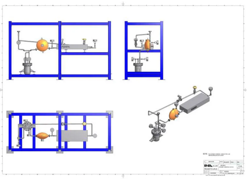
Figure 2: general layout of Lifus 6 loop ... 8
Figure 3: Lifus 6 piping and components ... 17
Figure 4: loop and support skid ... 18
Figure 5: nodalisation of the longest pipe, with material selection ... 19
Figure 6: displacement of pipe at 400°C ... 20
Figure 7: stress configuration at design temperature (400°C) ... 20
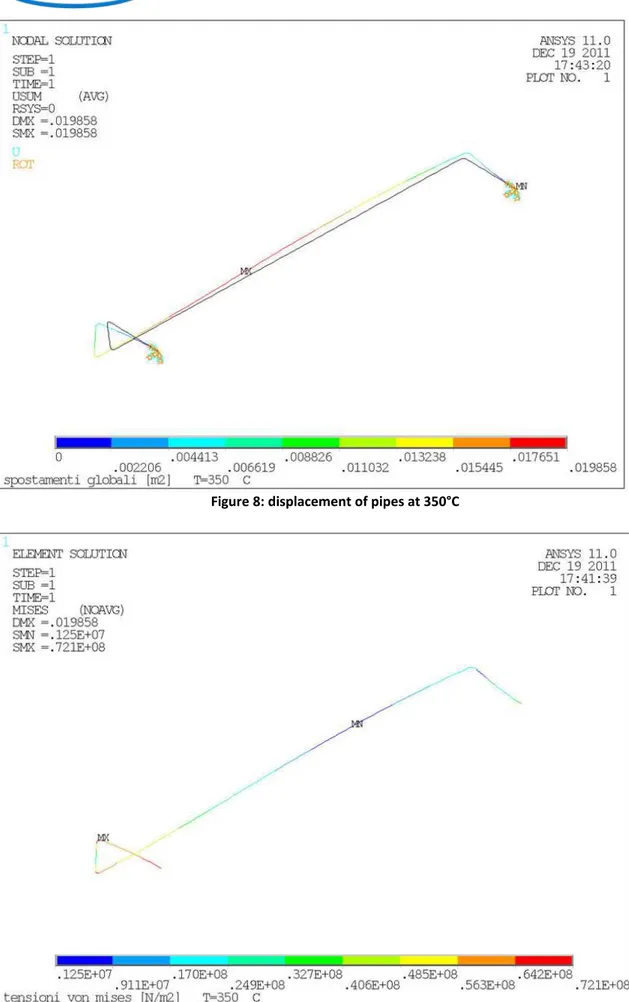
Figure 8: displacement of pipes at 350°C ... 21
Figure 9: stress configuration at 350°C ... 21
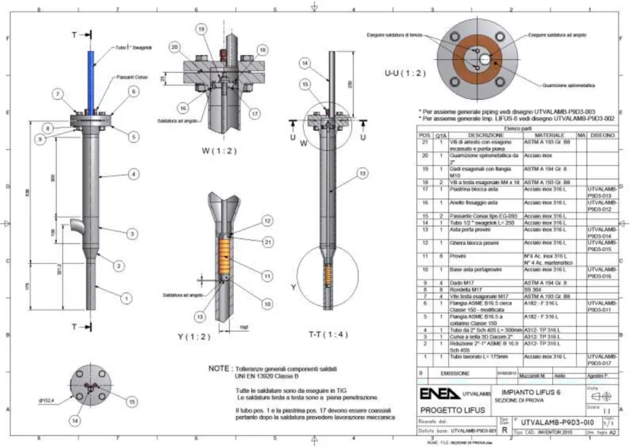
Figure 10: test section external view ... 24
Introduction
The evacuation of a large amount of heat (10 MW deposited beam power on a section of 0.01 m2) from the beam foot print area and the prevention of the lithium boiling necessitates a flow of lithium at a velocity of 10 to 20 m/s in the IFMIF target. The investigation of a possible subsequent corrosion/erosion effect is of importance for the EVEDA phase in order to assess the lifetime of the exposed target components; in particular of the nozzle and the backplate. Local shape modifications due to erosion/corrosion could give rise to flow instabilities leading to uncontrolled Li film thickness or massive spills, leading to a beam trip off and stop of IFMIF’s operation.
In the reference design for the IFMIF target [1] limits of the erosion/corrosion rate have been specified as:
1 µm per year in the target
50 µm over 30 years in the loop
The goal of the current PA is to measure the erosion and corrosion rates of selected materials in relevant conditions, with the aim to provide evidence that these values can be achieved with the materials and operating conditions selected.
Past experience
The Lifus 3 loop (fig. 1) was designed and constructed in 2001/2002 in ENEA, to evaluate the corrosion behaviour of Fusion reference structural materials, and in particular AISI 316 and Eurofer, in lithium environment in IFMIF relevant conditions. The original mission was to examine how the corrosion behaviour of the selected materials is affected by the impurities (C, N, H, etc.) which were said to be capable of playing a significant role in influencing the corrosion rate [1].
The LIFUS 3 loop work was focused on corrosion tests over EUROFER 97 and AISI 316L steels, as well as on lithium purification and monitoring experiments.
The operation of the loop was affected by several problems, mainly due to the complexity of system hydraulics, with the main circuit and the purification circuit working in parallel using only one pump, and the original commitments were not fully accomplished.
For this reason it was decided in 2010 to build a new experimental facility, simplified from the hydraulic point of view, capable to perform the set of tests required by the IFMIF community. This new loop, named Lifus 6, is hereafter presented.
7
Loop configuration and test setup
A series of erosion/corrosion tests shall be performed in the LIFUS 6 test loop (see Figg. 2, 3 and 4) at constant temperature of 350°C and Li flow velocity up to 16 m/s, impurity level, temperature, exposure duration and specimen materials with the goal to validate the choice of material made in the IFMIF reference design. The materials to be tested are mounted in a test section specially designed to achieve the specified Li flow velocities.
The Lifus 6 loop, in its operational configuration appears as a ring installed on a steel frame. The loop is not accessible during the operational phases and it is made of the following components:
Drain/storage tank mounted on mobile supports to compensate the thermal expansion of the pipes. It is complete of electric tracing, thermocouples for regulation, safety and measure of the wall temperature, nozzles for connection to the piping. The tank also acts as hot trap at a temperature of 600°C during the off line purification of lithium from nitrogen impurities. In normal operation the storage lithium is maintained melted at about 300°C.
Electromagnetic pump type GAAA IP 121 provided of air cooling system.
Two flow meters:
o The first one is a Vortex volumetric type, calibrated for a minimum flow velocity of 0.08 m/s and maximum 2.7 m/s corresponding to 0.40 – 5.4 m3/h
o The second one is a Coriolis mass flow meter, with a range of 0-4000 kg/h of liquid metal. Test section, in which the liquid metal reaches the foreseen testing conditions of velocity.
The Lifus6 loop is designed to perform corrosion/erosion tests in the following conditions:
Lithium velocity up to 16 m/s
Constant temperature along the loop of 350°C
According to fig.2, the Lithium flow at the pump outlet is divided in two parts. The main flow is driven to the test section and come back to the pump. A limited flow, about 1% of the total flow, enters instead the dedicated purification loop (subject of the Deliverable LF 4.4.1), where it passes through the Cold Trap (operated ad 200°C) to be continuously purified, essentially from carbon and oxygen. Materials to be tested are Eurofer 97 and AISI 316 Stainless Steel.
In the next paragraphs the design of the loop is presented.
Lifus 6 loop design
As mentioned, the plant has a ring structure whose layout is shown in figure 2.
Two separate circuits can be easily identified: the liquid metal circuit, piping 1" and the gas lines made entirely with Swagelok pipes ½”.
The liquid metal circuit is characterized by the following components:
Electromagnetic pump model IP 121 manufactured by the GAAA Company. The best operational point is reached at 12 m3/h of volumetric flow rate with a head of 2.5 bar;
Pneumatic Control Valve 1 ";
Vortex Flowmeter, Rosemount model 8800;
Test section, in which are reached the test conditions of fluid velocity;
Coriolis mass flowmeter, Emerson Micro Motion DT65;
Pressure gauges Gefran FO53732 in direct contact with liquid metal;
Piping in AISI 316 L 1" Schedule 40;
Storage tank.
The main purpose of the gas circuit is to maintain safety conditions during operation and plant stops, and therefore the strong control of oxygen and water in all possible loop conditions and in particular in loading and drainage phases. The liquid metal circuit is electrically heated and thermal insulated to guarantee a constant and uniform temperature of 350°C during operation.
H5 H5 H-4 H-3 H-1 H-1 H-1 E-2 E-1 DO L-1 DO L-2 DO L-3 DO L-4 DO L-5 AO PT-5 R-2 P-6 AO PT-1 P-33 P-5 AO PT-3 V-8 P-19 P-13 P-16 P-14 V-7 V-6 AO PT-4 P-36 P-3 P-2 P-4 P-7 P-9 P-15 P-24 V-9 P-25 P-21 P-20 P-23 P-26 V-10 P-27 P-28 P-31 P-29 V-3 V-12 F F-3 P-34 V-2 V-1 P-22 V-14 E-4 P-41 P-42 P-43E-5 P-44
ü Gas lines (argon) ü Gas lines (air)
ü Vacuum lines ü Lithium lines ü Lithium purification system ü Heathing cables V-15
Lithium loading line
F F-1 P-11 F F-2 R-1 V-13 V-17 V-16 V-18 P-45 P-46 V-5 K TC2 K TC3 K TC5 K TC8 K TC10 AI/AO I-27 AI/AO AT3 DI/DO AT4 H-15 DI/DO I-30 DI/DO AT2 DI/DO AT1 K TC4 K TC6 K TC7 K TC-11 K TC13 K TC14 K TC15 K TC16 K TC17 K TC18 K TC1 K TC-37 K T C -1 2 DI/DO I-50 DI/DO I-51 DI/DO I-52 DI/DO I-53 DI/DO I-54 DI/DO I-55 DI/DO I-56 DI/DO I-57 K TC21 K TC22 K TC19 K TC20 K TC23 K TC24 P-29 K TC9 P-29 P-9 P-10 E-3 P-1 H-8 K TC-56 K TC-52 PP-02 PP-03 PP-05 PP-04 AO PT-2 K TC-25 K TC-26 K TC-27 HRM K TC28 K TC-30 K TC-29 K TC-31 K TC34 K TC33 COLD TRAP (200°C) PP-06 PP-07 K TC-47 K TC-46 K TC-40 K TC-41 K TC-38 K TC-39 GP-01 H-16 K TC-44 K TC-45 V-11 H-15 H-14 PV-01 R-01 HV-03 HV-02 SAMPLER VP-01 SP-00 VP-01 SP-01 SP-02 SP-03 H-17 H-17 H-17 K TC-43 K TC-42 H-2 H-2 H-15 RESISTIVITY METER H-6 H-6 H-5 H-10 H-11 H-12 H-13 K TC-35 K TC-36 P-40 H-7 E-1 FAN-E K TCE-5 K TCE-6 K TCE-1 K TCE-2 K TCE-3 K TCE-4 In Out STATOR HE-1 HE-2 EMP E-1 K TC-49 K TC-50 S-7 S-3 K TC-54 K TC-55 P-30 K TC-51 K TC-63 K TC-64 K TC-53 DI/DO I-107 PP-01 VS-12 DI/DO I-108 VS-3 DI/DO I-109 V-4 DI/DO I-110 DI/DO EMG DI/DO ALM-OUT EMERGENCY BUTTON ALARM BELL DI/DO FIRE FIRE / FUME ALARM
LIFUS6 – P&ID
9
Thermal Dimensioning
The system is entirely electrically traced to ensure the operating temperature and prevent freezing of the liquid metal in the circuit in any possible accidental and ordinary condition. The installed thermal power and thermal insulation have been determined as follow.
Thermal insulation
To reduce as much as possible thermal losses the loop is thermal insulated. The thermal insulation is designed to maintain a maximum surface temperature lower than 50°C.
The general equation to determine the surface temperature is:
*
U
S
P
T
T
th is es
In which: U*((sacc/kacc)(sthi/kthi) )1
P
th is the thermal power globally exchanged with the environment
T
is is the temperature of the pipe surface, assumed as equal to the one of flowing lithium(conservative assumption) 350°C.
The thermal power Pth can be estimated using the formula:
T
S
U
P
th
In which: 1 )) / ( ) / ( ) / 1 (( hext sst kst sthi kthi
U
h
d
S
ext
)
(
T
sT
rT
Considering that the largest part of the loop is realized with 1” steel pipes, the evaluation can be conducted assuming a uniform pipe diameter.
The general parameters adopted are: Tr: 10°C
hext: 7,5 W/m2 K kst: 25 W/m K kthi: 0,05 W/m K
Using an iterative calculation procedure, the minimum thermal insulation thickness to respect the imposed outer temperature is 30 mm. To further reduce the thermal losses a thickness of 70 mm is selected.
The same procedure can be applied to the thermal insulation of the storage tank, that will be operated at 600°C during the purification phase. In this case, using the same equations, the thickness of the thermal insulation is 150 mm.
Heating power
Fixed the thermal insulation, the thermal power dispersed in the environment can be determined using the general correlations reported in the previous paragraph.
Per 1 meter length of tube the surface to be heated is about 0.5 m2.
Assuming that the insulator surface is at 50°C and the air constantly at 10° C it can be assumed, simplifying, that each meter of pipe has a dispersion of about 100 W. This value represents the minimum power that should be provided to the tube, per unit length, to maintain the pipe surface at 350°C with the selected insulation and the surface of the insulating material at 50°C.
To operate the loop in the best conditions of safety and reliability and to reduce the risk of breakage of the heating cables, the installed thermal power is more than doubled, thus limiting the maximum power
required to compensate dispersions below 50% of the one available, and giving an adequate reserve to be used in abnormal conditions.
Performing the same evaluation on the storage tank, the minimum thermal power results about two times higher, per surface unit, with respect to pipe, coherently with the maximum storage temperature of 600°C during purification.
Pre heating time
To reduce the thermal stresses on pipes during the heating phase, the temperature increase is usually fixed to a value of 10°C/h. To verify the respect of this condition, the heating time can be determined with the equation: i disp i elet r f p i P P T T c M t , , ) ( where i
M
mass of the i pipe
p
c
specific heat of steel: 460 J/Kg °C
f
T
final temperature to be reached: 350°C
r
T
room temperature: 10°Ci elet
P ,
electrical power of the heating cable;
i disp
P ,
thermal power dispersed in the environment.
Considering the installed thermal power, the preheating time is lower than 4 hours, corresponding to a ramp of almost 100°C/h. The thermal power available allows to have times of pre heating much lower than required.
The same evaluation should be made for the storage tank, filled of lithium before charging the loop. Also in this case the condition is perfectly respected, considering the low density of lithium and the fact that about 50 kJ are necessary to increase the temperature of lithium up to 350°C, negligible with respect to the dispersed thermal power.
Fluid dynamic analysis of the loop
Pressure drops
The general equation to determine pressure drops in a hydraulic system is:
2
ρv
K
Δp
2
(1) In which: T c a r MK
K
K
K
D
L
f
K
(2)
M 10 MRe
f
2.51
3.7
ε
2log
f
1
(Colebrook equation) (3) μ D v ρ Re Reynolds number (4)11
M
f
→ Distributed pressure dropsr
K
→ Pressure drop coefficient in case of reduction of pipe section = 0.5a
K
→ Pressure drop coefficient for pipe enlargement =1c
K
→ Pressure drop coefficient for bended tube = 0.75T
K
→ Pressure drop coefficient in a T joint = 0.4D → Pipe internal diameter
→ Fluid viscosity
→ Fluid densityRe → Reynolds number
L → Pipe length
→ Pipe roughnessDividing the loop separating each part with different pressure drop characteristics, the fluid pressure in the loop can be draftly evaluated:
Bent C1 Δp [Pa] 8,6605E+01 kc1 0,49435
Bent C2 Δp [Pa] 8,6605E+01 kc2 0,49435
Bent C3 Δp [Pa] 8,6605E+01 kc3 0,49435
Bent C4 Δp [Pa] 8,6605E+01 kc4 0,49435
Bent C5 Δp [Pa] 8,6605E+01 kc5 0,49435
Bent C6 Δp [Pa] 8,6605E+01 kc6 0,49435
Bent C7 Δp [Pa] 8,6605E+01 kc7 0,49435
Bent C8 Δp [Pa] 8,6605E+01 kc8 0,49435
Bent C9 Δp [Pa] 8,6605E+01 kc9 0,49435
P [Pa] T [°C] ρ [ kg/m3] Internal Diameter [m] Velocity [m/s]
Point 1 4,0000E+05 350,00 499,85 0,02664 0,8372 Point 2 3,9997E+05 350,00 499,85 0,02664 0,8372 Point 3 3,9988E+05 350,00 499,85 0,02664 0,8372 Point 4 3,9981E+05 350,00 499,85 0,02664 0,8372 Point 5 3,9973E+05 350,00 499,85 0,02664 0,8372 Point 6 3,9969E+05 350,00 499,85 0,02664 0,8372 Point 7 3,7874E+05 350,00 499,85 0,02664 0,8372 Point 8 3,7863E+05 350,00 499,85 0,02664 0,8372 Point 9 3,7806E+05 350,00 499,85 0,02664 0,8372 Point 10 3,7783E+05 350,00 499,85 0,02664 0,8372 Point 11 3,7775E+05 350,00 499,85 0,02664 0,8372 Point 12 3,7768E+05 350,00 499,85 0,02664 0,8372 Point 13 3,7759E+05 350,00 499,85 0,02664 0,8372 Point 14 3,7755E+05 350,00 499,85 0,02664 0,8372 Point 15 3,1471E+05 350,00 499,85 0,02664 0,8372 Point 16 3,1470E+05 350,00 499,85 0,02664 0,8372
Point 17 2,9375E+05 350,00 499,85 0,02664 0,8372 Point 18 2,9373E+05 350,00 499,85 0,02664 0,8372 Point 19 2,9365E+05 350,00 499,85 0,02664 0,8372 Point 20 2,9362E+05 350,00 499,85 0,02664 0,8372 Point 21 2,9354E+05 350,00 499,85 0,02664 0,8372 Point 22 2,9348E+05 350,00 499,85 0,02664 0,8372 Point 23 2,9339E+05 350,00 499,85 0,02664 0,8372 Point 24 2,9337E+05 350,00 499,85 0,02664 0,8372 Point 25 2,9328E+05 350,00 499,85 0,02664 0,8372 Point 26 2,9324E+05 350,00 499,85 0,02664 0,8372 Point 27 2,9315E+05 350,00 499,85 0,02664 0,8372 Point 28 2,9312E+05 350,00 499,85 0,02664 0,8372 Point 29 2,8157E+05 350,00 499,85 0,02664 0,8372 Point 30 2,8156E+05 350,00 499,85 0,02664 0,8372
13 P ip e N o d es Leng th [m] Intern. Diameter [m] Extern. Diameter [m] Rou gh n es s [m ] Average Pressure
[Pa] Averag
e T [° C] Average Density [kg/m3] Average Viscosity [Pa*s] Velocity [m/s] Re Friction coeff. Pressure drop [Pa]
P-3 1-2 0,22 0,02664 0,03340 5,0E-05 4,00E+05 350 499,85 4,08E-04 0,8372 2,7345E+04 2,3466E-02 33,950 3-4 0,43833 0,02664 0,03340 5,0E-05 4,00E+05 350 499,85 4,08E-04 0,8372 2,7345E+04 2,3466E-02 67,642 5-6 0,22912 0,02664 0,03340 5,0E-05 4,00E+05 350 499,85 4,08E-04 0,8372 2,7345E+04 2,3466E-02 35,357 7-8 0,69734 0,02664 0,03340 5,0E-05 4,00E+05 350 499,85 4,08E-04 0,8372 2,7345E+04 2,3466E-02 107,612 9-10 1,50625 0,02664 0,03340 5,0E-05 3,79E+05 350 499,85 4,08E-04 0,8372 2,7345E+04 2,3466E-02 232,440 11-12 0,448 0,02664 0,03340 5,0E-05 3,78E+05 350 499,85 4,08E-04 0,8372 2,7345E+04 2,3466E-02 69,13 13-14 0,28292 0,02664 0,03340 5,0E-05 3,78E+05 350 499,85 4,08E-04 0,8372 2,7345E+04 2,3466E-02 43,659 15-16 0,1 0,02664 0,03340 5,0E-05 3,78E+05 350 499,85 4,08E-04 0,8372 2,7345E+04 2,3466E-02 15,432 17-18 0,1 0,02664 0,03340 5,0E-05 2,94E+05 350 499,85 4,08E-04 0,8372 2,7345E+04 2,3466E-02 15,432 19-20 0,14943 0,02664 0,03340 5,0E-05 3,78E+05 350 499,85 4,08E-04 0,8372 2,7345E+04 2,3466E-02 23,0596 21-22 0,36887 0,02664 0,03340 5,0E-05 3,15E+05 350 499,85 4,08E-04 0,8372 2,7345E+04 2,3466E-02 56,9230 23-24 0,14943 0,02664 0,03340 5,0E-05 2,94E+05 350 499,85 4,08E-04 0,8372 2,7345E+04 2,3466E-02 23,0596 25-26 0,26897 0,02664 0,03340 5,0E-05 2,94E+05 350 499,85 4,08E-04 0,8372 2,7345E+04 2,3466E-02 41,5067 27-28 0,19924 0,02664 0,03340 5,0E-05 2,93E+05 350 499,85 4,08E-04 0,8372 2,7345E+04 2,3466E-02 30,7462 29-30 0,07591 0,02664 0,03340 5,0E-05 2,93E+05 350 499,85 4,08E-04 0,8372 2,7345E+04 2,3466E-02 11,7142
Pressure drops are concentrated in the test section and in valves. Appling the same procedure to valves on the main loop, the results are: Valve V2 Valve V4 Cv 3 K1 Cv 3 K1 Gf 0,49985 K2 Gf 0,49985 K2 N1 0,865 KB1 N1 0,865 KB1 d [mm] 26,64 KB2 d [mm] 26,64 KB2 N2 0,00214 Σk N2 0,00214 Σk
Fp 1,0000 Δp [Pa] 2,0950E03 Fp 1,0000 Δp [Pa] 2,0950E03
Max flow rate Max flow rate
FF 0,96000 K1 FF 0,96000 K1
FL 0,90000 FLP FL 0,90000 FLP
15
Pressure drops in the loop, excluding the test section, are lower than 0.5 bar. The test section is the main source of pressure drops as hereafter calculated:
Test section Pipe internal diameter Dsp [m] 0,021 Asp [m2] 3,4636E-04 vsp [m/s] 1,34734 Specimen diameter Dp [m] 0,02 Ap [m2] 3,2201E-05 vp [m/s] 14,49216 Test section inlet ki 0,49435 Δp [Pa] 8,6605E+01 Test section outlet
kip 4,5351E-01 Δp [Pa] 2,0576E+02
Specimens inlet
kip 8,2270E-01 Δp [Pa] 4,3184E+04
Specimens outlet
kip -3,0464E-01 Δp [Pa] -1,3821E+02
Distributed pressure drop Length [m] Intern. Diameter [m] Roughness [m] Average Temperature [°C] Average Density [kg/m3] Average Viscosity [Pa*s] Velocity [m/s] Re Friction coeff. Pressure drop [Pa]
0,075 0,021 5,0000E-05 350,0 499,85 4,08E-04 1,3473 3,4689E+04
2,2030E-02
3,5697E+01
0,12 0,001 5,0000E-05 350,0 499,85 4,08E-04 14,4922 1,7767E+04
2,3194E-02
1,4609E+05
0,075 0,021 5,0000E-05 350,0 499,85 4,08E-04 1,3473 3,4689E+04
2,2030E-02
3,5697E+01
ACCORDO DI PROGRAMMA MSE-ENEA
Pressure drops in the circuit are lower than 2,5 bars, compatible with the pump head, giving an adequate margin to operate the cold trap branch.
Mechanical design
In fig. 3 the entire loop is represented, while in fig. 4 the supporting structure in shown. The reference design parameters of the loop are:
T= 400°C (650°C for the storage tank) P= 0.4 MPa
The dimensioning of pipes has been made according to ASME B31.3 while the storage tank has been designed applying PED rules.
According to 1” pipe diameter, the reference schedule value given by ASME B31.3 is 10. We decided to use only sched 40 pipes, with a very high safety margin.
The same evaluation can be made for the storage tank. Also in this case the thickness is largely higher than the minimum allowed value.
ACCORDO DI PROGRAMMA MSE-ENEA
Thermomechanic analysis
The only fixed points of the loop are represented by the pump and the storage tank. Therefore, the pipes are free to expand, and mechanical stresses are negligible. To check in any case the real stress/strain situation a analysis of the longest pipe using Ansys was performed and results are show in figg. 5 to 9.
Figure 6: displacement of pipe at 400°C
21
Figure 8: displacement of pipes at 350°C
Ansys input parameters Material: AISI 316 STEEL
TEMPERATURE EXPANSION COEFFICIENT YOUNG MODULUS POISSON
[°C] [1/°C 10-6] [GPa ] 25 15.97 192.0 0.3 100 16.40 185.9 0.3 200 16.95 177.7 0.3 300 17.45 169.6 0.3 400 17.91 161.4 0.3 500 18.33 153.3 0.3 600 18.17 145.2 0.3
In fig. 5 the geometry and nodalization of the system is represented, at room temperature, with the assumed knots of no rotation or translation at the ends.
In fig. 6 the total elongation passing from room to 400°C temperature, the reference for design, is represented while in fig. 7 the stress is reported. The total elongation is about 23 mm with a stress of 7,21 MPa. At 350°C, fig. 8, the elongation is 19.8 mm with a stress of 7,21 MPa in fig. 9. The stress is almost the same due to the decrease of Young modulus increasing the temperature.
This value is very low, one order of magnitude lower than the basic allowable stress given by ASME B31.3, and in any case pipes are free to move thanks to flexible suspensions.
Test section design
For what concerns the test section, a detail of this is shown in fig. 10, while the assembly is in fig.11. The specimens have a cylindrical shape and are mounted on a rod fixed in the upper part to a removable centering plate, and supported on top and bottom of specimens assembly with centering systems. The centering plate is completely uncoupled with respect to the upper flange, to maintain the possibility to easily remove the upper flange and to use an extraction system to remove the specimen assembly, that will be surely stuck due to the presence of lithium.
With this solution it is realized a meatus in which the lithium flows at the design speed of at least 15 m/s. The triple anchoring of the support rod prevents the occurrence of vibrations in turbulent flow conditions. The outer diameter of the specimens is 20 mm, with a central hole of 3 mm, for the rod, and a height of 8 mm. The channel that hosts them has a diameter of 21 mm, with an external diameter corresponding to the one of a 1" standard pipe. The upper part of the test section, for a height of about 300 mm, is filled with Ar, in order to prevent any contact between the lithium and the sealing area of the flange. The pressure during operation will be about 2 bar, to compensate the pump head at test section inlet maintaining a constant level of lithium also during the start up of the pump. A double-level sensor is installed in the test section to control any accidental level climbs. The samples can be extracted by draining the system, opening the flange while maintaining the circuit in an inert atmosphere and removing the rod sample holder. This procedure ensures a limited contamination of the circuit and the maximum safety for the operators, reducing downtime for the replacement operations.
There is the possibility that lithium will reach the sealing area. That is the reason why the use of spiral wound sealing was preferred to ring joint, giving a higher guarantee on the clearness of the sealing area.
The connection with the circuit piping at inlet is made with a saddle-shaped coupling with 2” diameter to reduce the fluid velocity and the turbulence in the upper part of the test section about 5 cm of lithium are foreseen upper the joining to realize as much as possible calm fluid conditions and static free surface. This is necessary to avoid the transport of gas bubbles that should promote specimens erosions and pump cavitation.
23
The gas volume will act also as expansion tank in case of thermal expansion of lithium increasing the temperature or when launching the pump.
Instrumentation
The instrumentation system consists of:
Standard type K thermocouples, mounted on pipes surface;
Vortex Flowmeter Rosemount Model 8800, Scale 0.08 - 2.7 m/s;
Mass Flow Meter Coriolis type Micro Motion DT 65, scale 0-4000 kg/h
Liquid metal pressure gauge Gefran IE2-S-6-M-B01D-4-4-D-0-0, piezoelectric type, scale 0-10 bar;
Conductive level sensors in the storage tank and test section.
Instruments have been selected to be safe and suitable for use in lithium, at temperatures up to 350 ° C, and are provided with analog or Modbus type output, obviously excluding the thermocouples, or digital output.
Control System
The control system is based on National Instruments products. In particular for the PLC have been selected modules of the family CompactRIO able to guarantee the required performances.
The CompactRIO system is comparable to the market standard Siemens S7 on small systems such Lifus6, in which it is requested the management of a limited number of points. It has a greater ease of use being able to be fully programmed by NI LabView Real Time.
The loop will be remote controlled connecting the PLC via a standard TCP-IP address. Moreover, as happens on all PLC systems, in case of loss of network connection the system will maintain the last safe configuration set with a full management of abnormal situations and alarm.
The accurateness of the control system will be verified performing a series of tests in water, to determine the time of response of the pump/test section/ flow meter system.
Safety systems
To prevent injuries to personnel due to lithium leaks several safety measures have been adopted:
1. The experimental hall is completely isolated with safety doors during loop operations. The presence of personnel is not foreseen when the lithium is circulating, and the loop is remotely controlled. 2. A smoke reveal system can fastly identify the gaseous products of a reaction between lithium and
environment.
3. Pipes are protected with a leak detection system based on the use of electrical contacts. 4. Valves are protected with a leak detection system.
5. Steel tanks are installed under the loop to avoid contact between lithium and concrete.
Test and Evaluation Program
The test section is designed to perform three different corrosion test durations, hereafter presented:
Short term test
The first experimental campaign will have a duration of 2000 hours. The test matrix is given below. Four specimens, two per each material, will be extracted, while four will be leaved in the test section.
Run Material Velocity [m/s] Temperature [°C] Time [h] Nitrogen [wppm]
Roughness Ra [µm]
27
Analysis of the specimens comprises:
Cleaning of one sample and determination of the weight loss per unit of exposed surface (resolution 0.1 mg)
Cutting and metallography of the specimen surfaces, not cleaned, by optical and scanning electron microscopy, measuring the variation in inner diameter and roughness at three different heights along the specimen;
Elemental analysis of the residual metallic matrix by EDX;
Li will be analyzed at the end of the first run for impurity content determination.
Mid and Long term tests
After the end of short term test one half of the specimens will be substituted and a 4000 hours run will be performed. The total test duration in this phase will be about 6,000 hours. The test program is given below. Run Position Velocity [m/s] Temperature [°C] Time [h] Nitrogen
[wppm] Roughness Ra [µm] 2 SS/EF 16 350 4000 < 30 < 0.3 3 SS/EF 16 350 6000 < 30 < 0.3
Loop operations
Lithium filling
The Lifus6 loop will be full of lithium in its storage tank connected to the circulation pipes by two lines, one for the ordinary charging of the loop and the second one for the drainage. The tank is partially filled with titanium acting as nitrogen getter. To perform the purification of lithium before each charging the storage tank will be heated at 600°C. After this purification phase the storage tank will be cooled down at 300°C, and the system will be ready to be charged. The loop will be filled under vacuum. This is necessary to avoid the presence of gas in contact with pressure sensors. For this reason the inert gas in the loop will be evacuated using a vacuum pump. When the pressure is significantly lower than the atmospheric one, at least 10-1 mbar, the connection valve V2 between the storage tank and the loop will be opened. If necessary, to speed up the loop charging inert gas will be gradually injected in the storage tank until a complete filling is reached. The loop will be considered fully filled when the level sensor in the test section will be reached by liquid metal. The V2 valve will be closed. At the end of this phase the test section will be filled with high purity Ar gas at over atmospheric pressure to prevent lithium contamination form external atmosphere.
Start of Li circulation
After the lithium filling, the inner pressure in the test section is set at 2.05 bar.
Then the pump will be started at the lower possible power to start the circulation. The EMP voltage is progressively raised up to 235 V in order to assure a minimum flow rate of 28 l/m in the main loop. After temperature stabilization, it is necessary to verify the pump current. Since the current of each phase of the pump must not exceed 20 A, it is necessary to perform a check of all the three phases of the pump at regular time intervals. The operational pressure in the storage tank is regulated at 1.05 bar, the pressure in the loop is set at 1.1 bar to obtain a fast drainage in emergency.
At the same time the circulation in the main loop is started, the flow-rate in the purification line (in parallel) should be regulated to 5 cc/s. In order to respect the minimum residence time in the trap, the bypass flow rate can be regulated by operating the inlet pneumatic valve.
The operation should be necessary in normal operations or in emergency case. In the first case, after pump stopping, the intercepting valve V2 is opened remotely by the operator, and the test section and the storage tank are connected to have a continuous pressure equilibrium and the drainage by gravity of the loop. Then the heating cables of the loop are switched off. In case of emergency, the drain operation is automatically activated and the test section pressurized to have a fast drainage. The drain conditions are: lithium leak and smoke detection.
Conclusion
The construction of the loop in being completed, coherently with the presented design. The first tests with water are scheduled in November 2012, while the charging of lithium is foreseen in January 2013. Experimental activities will start at the end of the start up phase, approximately in March 2013.
29
References
1. IFMIF- KEP International Fusion Materials Irradiation Facility key element technology phase report, JAERI (2003)
2. A. Aiello, ‘Selection and development of materials for the monitoring and control of non-metallic impurities in liquid lithium’, ENEA Report IM-A-R-02 (2003)
List of Acronyms
Lifus 6 Experimental lithium flowing loop DACS Data Acquisition and Control Systems
IFMIF International Fusion Materials Irradiation Facility PLC Programmable logic controller
hext Convective
kst Thermal conductivity of steel
kthi Thermal conductivity of thermal insulation
h Convection factor
Ts e Tr Surface and room temperature
Tes e Tis External and internal surface temperature sst Steel thickness