STUDY OF A MICROCAR FOR ON-WHEELCHAIR DRIVERS
Devid GandiniDepartment of Mechanical Engineering University of Brescia Italy [email protected] Marco Gadola Stefano Uberti Gabriele Baronio Department of Mechanical Engineering
University of Brescia Italy [email protected] [email protected] [email protected]
ABSTRACT
The main purpose of this article is the feasibility study for a microcar with pneumatic suspension and facilitated access modality expressly designed for the disabled. Disabled people are potentially self-sufficient if they are endowed with aids necessary to overcome their own handicap. Driving aids allow the disable only to drive in autonomy but the real problem is represented by the access in the car such as entry/exit operations. The object of this work is to design a special car that can be driven in complete autonomy directly sitting on the wheel-chair and above all with an access modality without ramps or robotized arm. In this way the car can be used independently of the grade of disability of the driver because other systems of access are only good for certain type of disabilities but bad for others. The car developed in this work belongs to the family of the so-called microcars, small city-cars with 4 kW engines that can be driven beginning from 14 years old (in Italy).
KEYWORDS
Microcar, disability, autonomy, pneumatic suspension, aluminum chassis, wheelchair
1. INTRODUCTION
Since 1997 the Department of Mechanical Engineering of the University of Brescia has developed various plans about driving and transport systems for disabled people. The new philosophy that guides this work is to develop a car that can be driven in complete autonomy, independently from
the disability degree of the driver. Following this way, it is fundamental to avoid the current problems in the access operations, so the first thing that has been carried out in the plan definition has been the choice of the access modality.
2. PROJECT DEFINITION
The planning hasn’t been carried out in sequential way, but in parallel way and moreover it has been facilitated from the employment of 3D modeling, that has allowed to verify how the modification of a component influenced the entire layout of the car. The main points at the basis of this work are following:
Realization of a microcar conceived specifically for a disabled customer
To assure the maximum usability of the car for the disabled customer
To assure the maximum autonomy independently from the disability degree of the driver
To resolve problems concerning access modality with ramp or robotized arm
Possibility of maximum vehicle customization in function to the specific requirements of the customer
Planning of a modular chassis in extruded aluminum
Feasibility study of the pneumatic system for the raising and lowering of the car
Reduction of the cost of the plan
The first phase that has been carried out in the plan definition has been the choice of the access modality.
2.1. Access modality
There are essentially three different access modalities such as rear, front and lateral.
The access through a rear door is to be preferred substantially because there is no opening in the front zone which is fundamental for the torsional rigidity of the chassis. One of the main points at the basis of this work is to resolve problems concerning access ramps or robotized arms. These systems are only applicable for certain type of disabilities but bad for others. For example an access ramp, during entry introduces the problem of the slope and during exit must be run backwards and this is very difficult for some disable. Moreover, the solution without ramp is better for car parking, as shown in the following figures:
1520 mm
(A) With ramp
(B) Without ramp
920 mm
Figure 1 Comparison between the two constructive solutions
It has been decided to design the vehicle with lowerable bodywork. To allow for the lowering of the chassis it has been decided to adopt a pneumatic suspension device that will be explained afterwards. The next step in the vehicle project definition has been the choice of the engine, transmission and other
components because overall dimensions are important to define the chassis.
2.2. Engine and Transmission
European directive on the light quadricycles (92/61/CEE) limits installed horsepower to 4 kW. It has been decided to install a diesel engine Lombardini LDW 502 coupled with a CVT automatic transmission produced by Coram S.p.a.
Figure 2 Engine and transmission 3D models
2.3. Wheel Assembly
In order to reduce manufacturing cost it has been decided to use front and rear wheel assemblies produced by Coram S.p.a.
Front wheel assembly is expressly designed for McPherson kinematics. As will be explained, in order to reduce variations of wheel-track during lowering/raising it has been decided to employ a double wishbone suspension because with this kinematics it is easier to achieve the design laws of motion. So it has been necessary to design a strut in order to adapt the McPherson wheel assembly to double wishbone kinematics.
2.4. Setting out of overall dimensions
for the vehicle
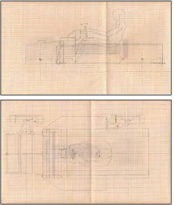
Beginning from scratch it has been studied the lay-out, chassis, kinematics suspensions and pneumatic suspension device for the lowering/rising of the bodywork. The overall dimensions for the vehicle has been set by drawing the chassis around the on wheelchair driver and the transmission assembly, as shown in the following picture representing the preliminary sketch of the vehicle ad chassis.
Figure 3 One of the preliminary sketches of the vehicle
Figure 4 One of the preliminary sketches of the chassis
Figure 5 Preliminary sketch of aluminum extruded joints
After quite a few iterations, the following overall dimensions have been defined:
Vehicle length (approx.): 2700 mm Vehicle width (approx.) : 1600 mm Vehicle height (approx.) : 1770 mm Minimum static height : 180 mm Front wheel-track : 1416 mm Rear wheel-track : 1400 mm Wheelbase : 1812 mm
Height of center of gravity (approx.) : 500 mm Height of center of gravity in running conditions
(approx.) : 620 mm
Yaw moment of inertia : 271 Kg.m2
Yaw moment of inertia in running conditions: 321 Kg.m2
Dry vehicle mass distribution : 66%Front - 34% Rear
Vehicle mass distribution in running conditions: 56%Front – 44%Rear
Dry mass : 350 Kg (prescribed mass)
Mass in running conditions (approx.) : 450 Kg
3. VEHICLE DESCRIPTION
The vehicle is a microcar expressly designed for on-wheelchair driver. The chassis is a monocoque in extruded aluminum jointed with an aluminum honeycomb floor. On the upper part the chassis is closed with a carbon steel roll-cage while there are two steel side frames that has the function to support rear suspensions. Front suspensions adopts double wishbone kinematics with upper rocker arm, in-board pneumatic springs and anti-roll bar. Rear there are independent longitudinal arms, in board pneumatic springs and anti-roll bar.
Wheel rims are 13” diameters, 5” width and 21,95 mm lateral offset. The engine is the Lombardini LDW 502 twin cylinder diesel engine coupled with an automatic CVT transmission by Coram S.p.a. Bodywork is made from fiberglass and it is fixed to the chassis by means of silent-blocks. Rear hatch is made from fiberglass too with structural function. In order to transmit shear action, during the closing of the hatch, there are some taper pins that fit in conical bushes fixed on the roll-bar.
3.1. The chassis
The chassis has been developed in two different versions: the first is entirely made of extruded aluminum, the second with the same extruded aluminum cockpit but with a front steel cage to support the engine and front suspensions.
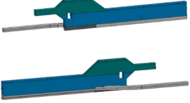
The lateral beams are arranged longitudinally and are parallel to make the structure of the cockpit. The distance between the lateral beams is 800 mm. Lateral beams are constituted overlapping 3 extruded of which two has the same section.
Figure 6 Perspective view of the lateral beam
In order to support the engine in front it has been decided to connect across the car the two extensions of the main beams with some extruded beams that, beyond constituting the eventual support for engine silent-blocks, they act as attacks for inferior arms of the front suspensions. The two lateral beams then are connected frontally to a beam (modular too) always realized with the same extruded sections, that in short determines the separation wall between the engine space and the cockpit.
Figure 7 View of front beam and assembly
On the upper side the two lateral beams, are jointed with a roll-cage made with carbon steel that in addition to protect the driver in the case of a roll-over, has a structural function because it determines the rear closing of the chassis contributing therefore to the torsional stiffness. In the lower part the chassis is closed with an aluminum sandwich panel fixed, through epoxy resin and structural rivets, to a groove in the inferior element of the lateral beams and the front beam. This aluminum sandwich panel, apart from contributing to the torsional-stiffness of the chassis, constitutes also the base of the cockpit.
Figure 8 Perspective view of the chassis.
The front has been conceived to install the following reinforce structures :
Triangular reinforcement that connects the upper element of the lateral beam with the folded inferior beam
adjustable strut braces for the connection of the two upper beam.
Inside the upper element of the lateral beams it has been decided to insert an aluminum reinforcement that can be built up with extrusion or with machine tools.
Two frames made of low-carbon steel are fitted laterally. These have the main function of supporting the oscillating arms of the rear suspensions; not to forget also the function about protection they offer to the driver in the case of a lateral crash.
The second solution that has been studied, differs from the first because, instead of an integral chassis, there is an auxiliary frame made up of low-carbon steel which supports the engine and the front suspension lower arm.
Figure 9 View of the second solution of the chassis
3.2. Front suspension kinematics
It has been decided to adopt a double wishbone, with upper arms far apart from lower one, in order to transfer low forces to the chassis. Upper arm, for kinematics requirements, is relatively short and this, considered the high excursion of the suspension, determines a large rotation of the same one.
88.6 9° 68.91 ° 83.62 ° 118 .79°
Figure 10 Front suspensions on 60 millimeters rebound conditions 48.25° 10 1.4° 41.8° 168. 54°
Figure 11 Front suspensions on 180 millimeters bump conditions (chassis totally lowered)
Therefore the upper ball-joint must rotate about 77° but this value is too large for commercial ball-joints. So it has been decided to disengage the degrees of freedom of the "upper ball-joint” in order to solve the problem of the excessive angle of rotation. Therefore the kinematics disengagement has been realized in the way represented in figures 12 and 13:
Figure 12 Front suspension kinematics with upper rocker arm and disengaged upper ball-joint.
Figure 13 View of the disengaged upper ball-joint
In order to disengage the rotational degree, that allows the steering, it is decided to integrate in the strut a double row angular contact ball bearing. In order to allow the recovery of Caster during suspension bump, two rubber-metal bushes are mounted inside the pivot, so through their elasticity it is possible to achieve the d.o.f desired.
The kinematics study has been carried out within the program of simulation, specific for groups suspension, "MLK Race" developed inside the Department of Mechanical Engineering of Brescia University. Particular attention has been placed about the behavior of the suspension in three different situations:
Bump(shaking of the wheel in vertical direction) Steer(wheel steering at a fixed angle)
Bump-Steer(wheel steering induced during bump)
Figure 14 Snapshot of “MLK Race” : front suspension kinematics
Through Bump analysis the static parameters characteristics of the front suspension (Caster, Kingpin, Caster offset, Kingpin offset) have been tuned and how these parameters change during the wheel movements. In other words, it has been
possible to study how all the geometrical parameters of the suspension change during bump or rebound. During the dynamic operation of the suspension from –60 mm to +80 mm, Camber angle change from – 0,41° to –1,40° starting from 0° static Camber.
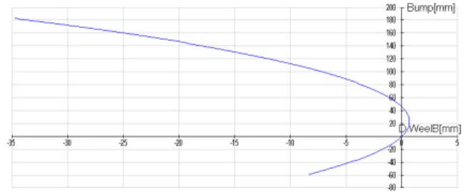
Figure 15 Bump analysis: Lateral scrub on the single wheel
The diagram of figure 15 is has strongly influenced the design of the front suspension, because the main purpose was to reduce the value of the lateral scrub on the single wheel. High lateral scrub could result in very difficult(or impossible)car lowering. After a great number of optimization iterations, lateral scrub, during lowering , has been reduced approximately to 3,6mm towards the outside and 2,4mm towards the inside. Such values should be compatible with the deformation of the tire shoulder and probably during the lowering no lateral slip between wheel and ground should occur. However given the peculiarity of this vehicle, it is advisable to fit tyres with fairly flexible shoulders, with /70 aspect ratio for instance.
3.3. Rear suspension kinematics
It has been decided to adopt independent suspension kinematics with longitudinal arms fixed to an auxiliary steel frame, rigidly assembled to the lateral chassis beam. The rear suspension has been defined through an accurate study that allows to have a good behavior of the suspension. The connection of the oscillating arm with the lateral frame, cannot be of rigid type (realized by means of bearings) but necessarily it must be an elastic connection to filter the vibrations that, through the suspension, would be transmitted to the chassis, therefore reducing the level of comfort.
Figure 16 Rear suspension : oscillating arm
Figure 17 Rear suspension: mounting to lateral frame
Figure 18 Snapshot of “MLK Race” : rear suspension kinematics
In this case only a bump analysis has been made. It has been decided to adopt an "anti-lift" geometry. The static percentage of anti-lift is 11% with an angle of the oscillating arm, of approximately 3,45°. At percentage of 100% anti-lift geometry the angle is approximately 29°, and in this case the rear part of the car is not raised but the suspension remains "locked". In order to give the driver the brake feeling
is better to have suspension with low percentages of anti-lift.
Figure 19 Rear suspension : Anti-lift percentage.
This geometry produces no lateral scrub but in this case, because the pivot arm is transversal, during bump or rebound suspension there is an high variation of wheelbase, so it is important to mount the emergency brake on the front axis, in order to permit the lowering/raising of the vehicle.
Figure 20 Rear suspension : Wheelbase variations
3.4. FEM Analysis
A FEM analysis has been done on the main structural members of the chassis, applying the following load cases:
Load produced by a vertical acceleration of 4g. Load produced by a lateral acceleration of 0,6g. Load produced by a braking deceleration of 1g The results of FEM simulations have confirmed that the structure is sufficiently strong, with a good safety factor, for common street use.
In the pictures below there are some results obtained with FEM analysis.
Figure 21 Cornering at 0,6g : displacements
Figure 22 4g bump: Von Mises stress on the upper arm of the front suspension
Figure 23 Cornering at 0,6g : Von Mises stress on the oscillating arm of the rear suspension
3.5. Pneumatic suspension assembly
In this paragraph the pneumatic suspension system is explained. It has been studied in order to perform the ride function and above all in order to allow the lowering of the bodywork down to the pavement. Every pneumatic suspension has a curve with a non linear behaviour: small force variations correspond to small displacements around the static position; Then the curve becomes steeper up to a vertical asymptote when the bump-stop comes into play.The philosophy of the pneumatic system developed in this work is to integrate the spring and damper functions in a single component.
As a matter of fact a monotube shock absorber is a system which contains a damper and an air spring:
Di Fo Oil Oil Dst Air
Figure 24 Layout of a monotube shock absorber
However, in order to counteract the suspension loads a high pressure or a large diameter floating piston is necessary. But the air pressure should be low (< 15 bar) because this is the maximum value of 12V air compressors. Moreover a large diameter piston is not compatible with the overall dimension of the vehicle.
For this reason a device based on a differential cylinder has been developed. The oil pressure generated by the load is transferred to the remote oil chamber. In this case in order to equilibrate the forces on the piston a low value of air pressure (
~
6bar) is enough and this value is compatible with
the project specifications.
Two different feasibility studies have been developed for the above reasons.
In the following picture the layout of the first pneumatic suspension assembly is shown.
Floating piston
Di Fo Oil Oil Dst Oil Air in pressure Dsts Dps Patm Shock absorber
Figure 25 Layout of the first pneumatic system developed
The aim of the idea is to create an alternative pneumatic system different from those already existing on the market, in such a way to have a suspension system created “ad hoc” for this particular type of vehicle. The system is essentially composed of two components:
Simple shock-absorber.
Separated tank with differential cylinder with function of pneumatic spring.
The working principle is based on the differential cylinder, that allows to reduce considerably the pressure of the compressed air necessary to counteract the suspension loads. The pressure generated by the load will be transmitted also to the chamber containing oil in the separate tank. But in this case the pressure goes to act on a different area. As a matter of fact in this case the relevant area is the stem area of the piston separator. A calculation sheet has been made in order to determine the geometrical parameters of the pneumatic suspension assembly. These are the values obtained:
Shock-absorber stroke, 180 mm bump: 115 mm Shock-absorber stroke, 80 mm bump: 49 mm Shock-absorber stroke, 60 mm rebound: 32 mm. The correspondents strokes of the piston separator in the separated tank are the following:
Stroke, 180 mm bump: 68 mm. Stroke, 80 mm bump: 29 mm. Stroke, 60 mm rebound: 19 mm.
The characteristic curve that is obtained for this type of pneumatic spring is the following:
Front suspension characteristic
0 2000 4000 6000 8000 10000 12000 14000 -40 -15 10 35 60 85 110 X [m m] F n et [ N ]
Figure 26 Pneumatic front suspension characteristic
The front suspension is non-linear and features a progressive stiffening characteristic in bump. As for the stiffness, the calculation sheet supplies, for every movement of the shock-absorber, the correspondent value of the suspension frequency. In the normal range of the suspension, between -60mm and +80mm, the frequencies are around 1,2 Hz.
Figure 27 The prototype of the separated tank (first solution)
Figure 26 show the layout of the pneumatic spring: observing the section view the piston separator that divides the air pressure chamber from the atmospheric air pressure is clearly visible.
The second solution has been thought with the attempt to improve the sealing by means of a membrane system and is represented in the figure below:
Piston separator
Stem guide
Air pressure Oil
Remote oil chamber
Oil Oil Oil H Hm D d r* R* Air pressure Patm F Shock absorber Membran Helper Spring dsts dst
Figure 28 Layout of the second pneumatic system developed
Figure 29 The prototype of the separated tank (second solution)
Figure 28 shows the layout of the pneumatic spring with separated tank: there are two aluminum flanges. One has a stem guide function and separates the pressure chambers. Observing the section view the rubber membrane that contains the pressurized air is clearly visible. The principle of construction and the design are the same for the rear suspension.
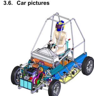
3.6. Car pictures
Figure 30 Front perspective view
Figure 31 Rear perspective view
Figure 32 Lateral view
Figure 33 Top view
4. CONCLUSIONS AND FUTURE
DEVELOPMENTS
This work has faced the main problems that are encountered in the design of a special car, proposing the solutions adopted in the specific case and developing, in a generalized manner, the entire “iter” that leads to the final definition of the car. The feasibility study has been therefore completed. However this is just a starting point for the complete design. This work doesn’t constitute the final design of the car. Before the manufacturing phase further developments are required, such as:
Feasibility study of the bending of the chassis lower beams.
Study of the rear structural hatch, the assembly to the roll-bar and the pneumatic opening mechanism.
Study of the wheelchair fastening devices to the floor of the car.
Study of a device integrated to the hatch that constitutes a valid back-rest and head-rest for the driver in order to increase safety in case of crash, coupled with a valid seat-belt.
Design study of the bodywork and cockpit, to be carried out by a design center or a school of industrial design.
Detailed analysis of the production costs. Elasto-kinematics and frequency analysis.
REFERENCES
Magnani, P., Cambiaghi, D.,Villa, V., (1999), “Devices for tetraplegic people: an innovative mechanical system for climbing aboard the driver car seat”; Tenth World Congress on the Theory of Machines and Mechanisms (IFToMM), Oulu, Finland, June 20–24, 1999.
Cambiagli, D., Faglia, R., Gadola, M., Vetturi, D., Villa, V., Arenghi, A., (1998), “On the design of an auxiliary device for disabled people”; IV International Congress of Project Engineering, Cordoba, Spain, 7-9 October 1998.
Cambiaghi D., Gadola M., Uberti S., Villa V., (2001), “Morphological Study of Man-Machine Interfaces in a Completely New Type of Car”; 12th ADM International Conference on Design Tools and Methods in Industrial Engineering, Rimini, September 5-7, 2001.
Gandini, D., (2005), “Studio di fattibilità per microvettura con sospensioni pneumatiche e modalità d’accesso agevolata”, Graduation thesis, University of Brescia, academic year 2004/2005.
Leone, L., Resentera, M., and Chignola, S., (2001), "Studio di fattibilità e progetto di una autovettura monoposto da competizione con struttura in lega leggera", Graduation thesis, University of Brescia, academic year 2000/2001.
Copeta, A., (2000), "Studio di fattibilità di un veicolo leggero per disabili. Modalità d’accesso e guida", Graduation thesis, University of Brescia, academic year 1999/2000.
Orlandi, G.L., Tomasoni, A., (2004), "Studio, progetto e realizzazione di una vettura da corsa di categoria sport prototipi slalom", Graduation thesis, University of Brescia, academic year 2003/2004.
Guiggiani, M.,(1989), "Dinamica del veicolo",Città Studi Edizioni.
Morelli, A., (2000), "Progetto dell’autoveicolo-Concetti di base", Celid.


