Università Politecnica delle Marche
Scuola di Dottorato di Ricerca in Scienze dell’Ingegneria Curriculum in Ingegneria Meccanica
Numerical study of cold rolling
process with variable thickness
Ph.D. Dissertation of:
Ing. Luca Maria Mattucci
Advisor:
Prof. Marco Sasso
Coadvisor:
Prof. Dario Amodio
Curriculum Supervisor: Prof. Ferruccio Mandorli
Università Politecnica delle Marche
Scuola di Dottorato di Ricerca in Scienze dell’Ingegneria Facoltà di Ingegneria
To my sons,
Elia and Sole
Acknowledgments
The author would like to express sincere gratitude to his supervisor, Prof. Eng. Marco Sasso, machine design professor at Università Politecnica delle Marche, for his guidance, support and encouragement throughout the course of this research.
The author is also deeply grateful to all the staff of machine design research group, an ING/IND-14 family rather than a working group. They really de-serve to be mentioned one by one, starting from Professor Dario Amodio, Marco Rossi, Edoardo Mancini, Gianluca Chiappini, Attilio Lattanzi, Massimo Natal-ini and last but not least Emanuele Farotti. He wishes to thank them all for the support, help and all the formidable shared moments throughout academic circumstances and not only.
Acknowledgement is also given to his parents for the enthusiastic support and continuous encouragement throughout these years.
The author would like to express sincere thanks to his darling wife Caterina, for her love, continuous encouragement and her patience during the Ph.D study. He hopes that she will be proud of this dissertation and finish line and that this will provide some sort of satisfaction after her many sacrifices such as living in Ancona... joke! Thanks to his children Elia and Maria Sole, thanks for being there, thanks for giving him such pleasure with their presence or funny pictures, videos and audio messages when being away from home!
Thank you all indeed! Ancona, November 2017
Abstract
The buzz word is metal replacement. Replacing those heavier older compo-nents with a plastic or composite is surely a logical exercise for anyone wanting to shed a few kg. Cars today, for example, are reportedly 50% by volume one type of plastic or another, but that represents only 10% of the overall weight. So, with all this talk about metal replacement where does the aluminium in-dustry fit in? While many associate exotic materials with weight reduction, the aluminium industry is keen to remind engineers it is also part of the solution.
Figure 1 – Aluminium diamond plate examples
The present research activity starts from the idea of an alluminium producer who intends to develop an innovative cold rolling technology able to incentivize the use of alluminium alloy in the automotive world, through the distribution of different thickness areas on the finished product. A very common aluminium diamond plate (shown in Figure 1) can be used to explain the concept of this kind of cold rolling process. However, the over-height related to the diamond is contained in a small area of 1÷2 cm2 .
The research activity set out hereinafter aims to validate the opportunity to vary shape and dimensions of those diamonds until remarkable size zones with increased thickness are obtained.
So after sharing all the cold rolling process information, i.e. cold rolling pa-rameters, rolling mill data and part of the study materials (Cold Rolling Hand-books, [1, 2]) the aluminium producer requested scientific support to validate the feasibility of this kind of technology and to identify limits or criticalities.
Contents
1 Introduction 1
2 The cold rolling process 5
2.1 Introduction . . . 5
2.2 Calculation of stresses distribution . . . 7
2.2.1 Simplifying assumptions . . . 7
2.2.2 Distribution of roll stresses along the arc of contact -“Slab Analysis” . . . 8
2.2.3 Solution of the Von Kármán differential equation . . . . 10
2.3 Cold rolling mills - a brief mention . . . 14
2.3.1 Sendzimir reversing rolling mills . . . 17
3 Aluminium and its alloys 23 3.1 Introduction . . . 23
3.2 Heat treatments . . . 26
3.3 Main aluminium alloys . . . 27
3.3.1 AA 5182 alloy . . . 29
3.3.2 AA 5754 aluminium alloy . . . 30
3.3.3 AA6016 aluminium alloy . . . 31
3.4 Hybrid aluminium composites . . . 32
3.4.1 DIBOND® . . . 33
3.4.2 HYLITE ® . . . 34
4 Characterisation of materials 37 4.1 Introduction . . . 37
Contents
4.1.2 The forming limit diagram . . . 41
4.1.3 Influence of material properties on formability . . . 44
4.1.4 Anisotropy of sheet-metals . . . 45
4.1.5 Influence of anisotropy on sheet-metal forming . . . 47
4.2 Experimental research activity . . . 48
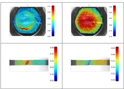
4.2.1 Experimental techniques . . . 49 4.2.2 Optical methods . . . 51 4.3 Results . . . 56 4.3.1 AA 5182 . . . 56 4.3.2 AA 5754 . . . 59 4.3.3 AA 6016 . . . 62 4.3.4 Hylite . . . 65 4.3.5 Dibond . . . 66
4.4 Choosing the material . . . 67
5 Preliminary numerical modeling 71 5.1 Introduction . . . 71
5.2 2D and 3D analysis . . . 72
5.2.1 State of art . . . 72
5.3 Finite Element Method analysis . . . 74
5.3.1 Aluminum plate 1200x1500 with 3 patches . . . 78
5.3.2 Aluminum plate 1200x1500 with 4 patches . . . 81
5.3.3 Aluminum plate 1200x1500 with 6 repeated patches . . 82
5.3.4 Aluminum plate 1200x1500 with full width patch . . . . 83
5.3.5 Aluminum plate 1200x1500 with arch patch . . . 85
5.4 Balance of the lengthwise deformation . . . 86
5.5 Hypothetical real case application . . . 91
6 Design Of Experiments and analysis of the results 95 6.1 Identification of the process parameters . . . 95
6.2 A brief reference to the Design Of Experiments . . . 98
6.3 Implementation of a Design of Experiments . . . 100 xiv
Contents
6.4 Analysis of the results . . . 107
6.4.1 Analysis of the thinning areas . . . 107
6.4.2 Analysis of the shear deformation . . . 118
7 Real case application 131 7.1 Small scale experimental test . . . 136
7.1.1 Test n.1 . . . 139
7.1.2 Test n.2 . . . 140
7.1.3 Test n.3 . . . 141
7.1.4 Test n.4 . . . 141
7.1.5 Test n.5 . . . 142
7.2 Full scale experimental test . . . 143
List of Figures
1.1 Ashby diagram, elongation VS specific strenght . . . 2
1.2 Technological scheme ofprofile rolling . . . . 3
2.1 Friction forces . . . 6
2.2 Unitary forces acting on the infinitesymal element object of study 9 2.3 Friction hill . . . 13
2.4 Influence of several parameters on the amplitude of the friction hill . . . 14
2.5 Tandem rolling scheme . . . 15
2.6 Reversible rolling mill scheme . . . 15
2.7 "Two High" cold rolling mill scheme . . . 16
2.8 "Four High" cold rolling mill scheme . . . 16
2.9 "Six High" cold rolling mill scheme, version 1 . . . 17
2.10 "Six High" cold rolling mill scheme, version 2 . . . 17
2.11 "ZHi" Sendzimir rolling mill scheme . . . 18
2.12 "20 Hi" Sendzimir cold rolling mill scheme - whole mill . . . 19
2.13 "20 Hi" Sendzimir cold rolling mill scheme - upper half (rolls) . 19 2.14 "20 Hi" Sendzimir cold rolling mill scheme - whole mill . . . 20
2.15 “Shifting” of first intermediate tapered rolls scheme . . . 21
2.16 . . . 21
3.1 Pure aluminium . . . 23
3.2 Aluminium hybrid composite . . . 33
3.3 DIBOND®layers detail . . . 33
List of Figures
4.1 Safe zone, failure zone and marginal zone in FLD . . . 42
4.2 Test conditions in FLD . . . 43
4.3 Strain effects. Respectively: negative strain effects and positive strain effects . . . 43
4.4 Some major and minor strain configurations . . . 44
4.5 Plastic anisotropy factor . . . 46
4.6 Normal and planar anisotropy . . . 47
4.7 Earing in deep drawing . . . 48
4.8 Tensile test set-up . . . 49
4.9 Nakazima test . . . 50
4.10 Specimen used in tensile tests with and without speckle pattern application . . . 52
4.11 Standard format specimens for aluminium formability test . . . 53
4.12 Intersection identification process . . . 54
4.13 AA5182 0° flow plastic curves . . . 57
4.14 AA5182 45° flow plastic curves . . . 57
4.15 AA5182 90° flow plastic curves . . . 58
4.16 AA5182 summary and characteristic parameters . . . 58
4.17 AA5182 Forming Limit Diagram . . . 59
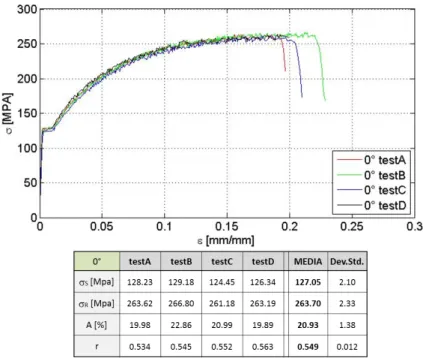
4.18 AA5754 0° flow plastic curves . . . 60
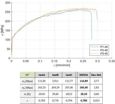
4.19 AA5754 45° flow plastic curves . . . 60
4.20 AA5754 90° flow plastic curves . . . 61
4.21 AA5754 summary and characteristic parameters . . . 61
4.22 AA5754 Forming Limit Diagram . . . 62
4.23 AA6016 0° flow plastic curves . . . 63
4.24 AA6016 45° flow plastic curves . . . 63
4.25 AA6016 90° flow plastic curves . . . 64
4.26 AA6016 summary and characteristic parameters . . . 64
4.27 AA6016 Forming Limit Diagram . . . 65
4.28 HYLITE flow plastic curves . . . 65
4.29 HYLITE Forming Limit Diagram . . . 66
4.30 DIBOND flow plastic curves . . . 66 xviii
List of Figures
4.31 DIBOND 2mm Forming Limit Diagram . . . 67
4.32 DIBOND 3mm Forming Limit Diagram . . . 67
5.1 2D model of profile-rolling mill . . . 71
5.2 Position of neutral point in profile rolling . . . 72
5.3 3D model of patch-rolling mill . . . 73
5.4 3D geometry of FE analysis . . . 74
5.5 AA5754 piecewise linear law . . . 75
5.6 Detail of the mesh in the thickness direction . . . 75
5.7 Eight-node, isoparametric, arbitrary hexahedral n.7 element type 76 5.8 Contact settings between upper and lower rolls and workpiece . 76 5.9 Detail of the front surface boundary condition applied . . . 77
5.10 . . . 78
5.11 Lengthwise component of plastic deformation . . . 79
5.12 . . . 80
5.13 Lengthwise component of plastic deformation at the end of rolling loadcase . . . 80
5.14 Lengthwise component of εp and side view after forces removal 81 5.15 . . . 81
5.16 Lengthwise component of εp of 2 patches model . . . 82
5.17 . . . 83
5.18 Lengthwise component of εp of 6 patches model . . . 83
5.19 . . . 84
5.20 Lengthwise component of εp of profile rolling . . . 85
5.21 . . . 85
5.22 Lengthwise component of εp of profile rolling with arch . . . 86
5.23 Discretization of a plate with overthickness . . . 87
5.24 . . . 88
5.25 . . . 89
5.26 . . . 90
5.27 . . . 91
List of Figures
5.29 Ideal full-balanced patch . . . 92
5.30 Full-balanced patches distribution . . . 92
5.31 Particular of the sketch enveloped on the cylinder . . . 93
5.32 Lengthwise component of εp of real application case profile rolling 94 6.1 Real case application example of the patch rolling process . . . 96
6.2 Graph of all the process variables . . . 97
6.3 First three analyses settings . . . 102
6.4 . . . 106
6.5 Location of the paths for ε22 and εV onM isesevaluation . . . 107
6.6 . . . 108 6.7 . . . 109 6.8 . . . 110 6.9 . . . 111 6.10 . . . 112 6.11 . . . 113 6.12 . . . 114 6.13 . . . 115 6.14 . . . 116 6.15 Principal effects on ε22 . . . 117
6.16 Principal effects on length of the thinning area . . . 118
6.17 Location of the paths for ε31=γ231 evaluation . . . 118
6.18 . . . 119 6.19 . . . 120 6.20 . . . 121 6.21 . . . 122 6.22 . . . 123 6.23 . . . 124 6.24 . . . 125 6.25 . . . 126 6.26 Principal effects on ε31 . . . 127
6.27 Principal effects on the amplitude of shear deformation range . 128 xx
List of Figures
6.28 . . . 128
6.29 2D geometric deformation of an infinitesimal material element . 129 6.30 . . . 130
7.1 Basic frame of the considered sliding door . . . 131
7.2 Over-thickness areas identification . . . 132
7.3 Ideal patch distribution on the welded blank . . . 133
7.4 Patch distribution according to the symmetry . . . 133
7.5 Definitive patch shape and distribution . . . 134
7.6 Patch sketch to be enveloped on the base cylinder . . . 134
7.7 Views of the obtained work-roll . . . 135
7.8 . . . 136
7.9 Cold rolling mill for small scale tests . . . 136
7.10 3D CAD of the work-roll . . . 137
7.11 . . . 138
7.12 Preliminary test result . . . 138
7.13 . . . 140
7.14 2nd test result with thickness measure . . . 140
7.15 3rd test result with thickness measure . . . 141
7.16 4th test result with thickness measure . . . 142
7.17 5th test result with thickness measure . . . 142
7.18 Technical drawing of the full scale work-roll . . . 144
7.19 Patch sketch to be enveloped on the base cylinder . . . 144
7.20 Dimensional drawing of all the patches . . . 145
7.21 Particulars of the A-B patch pair . . . 145
7.22 Particulars of the C-D patch pair . . . 146
7.23 . . . 146
7.24 Three moments of the full scale test . . . 147
7.25 . . . 147
List of Tables
3.1 AA5182 alloy chemical composition . . . 29 3.2 Main physical properties of AA5182 alloy at room temperature 30 3.3 Main processing properties of AA5182 alloy . . . 30 3.4 AA5754 alloy chemical composition . . . 30 3.5 Main physical properties of AA5754 alloy at room temperature 31 3.6 Main processing properties of AA5754 alloy . . . 31 3.7 AA6016 alloy chemical composition . . . 31 3.8 Main physical properties of AA6016 alloy at room temperature 32 3.9 Main processing properties of AA6016 alloy . . . 32 3.10 DIBOND®processing . . . 34 3.11 HYLITE®processing . . . 36 4.1 Calibration results . . . 51 4.2 Deformed specimens after Nakazima test . . . 53 4.3 3D surface – Nakazima test . . . 55 4.4 Maps of principal strains . . . 56 6.1 Definition of DoE (variables) . . . 100 6.2 Definition of DoE (levels) . . . 101 6.3 Adopted DoE . . . 101 6.4 DoE results in terms of ε22 minimum value . . . 117
6.5 DoE results in terms of length of the thinning area . . . 117 6.6 DoE results in terms of ε31 minimum value . . . 127
Chapter 1
Introduction
The low cost of the product coupled with the long-proven technologies for mass production make steel the most used material in the automotive industry. However, green economy policies such as weight and consumption containment are pushing for steel components to be replaced with aluminium alloy ones, especially parts formed by sheet metal.
Use of rolling products is constantly increasing in the automotive field: in addition to the coating and/or finishing role, the current trend is to use alu-minium alloy for structural components as well. However, technological sys-tems can not provide an adequate product when a high structural strength is required related to specific areas only (e.g. junctions with other components where localized stiffness is required). Consequently it translates into the use of more material than is necessary or with a global geometric over-dimensioning of any finished product or with additional processes, such as the addition of material through welded reinforcements. From a structural point of view, such over-dimensioning results in an increase of weight of the overall finished prod-uct and hence a rise in the operating costs of the vehicle, since consumption is strictly related to mass. From an energetic point of view it should be noted that any surplus of material is intrinsically related to a "waste" of the energy used in production processes, and subsequently an increase in the cost of the component.
As illustrated by the diagram in Figure 1.1, aluminium alloys (purple) show a good compromise between elongation at break (necessary for a good
forma-Chapter 1 Introduction
bility of component) and specific strength (i.e. the ratio of tensile strenght to density). However the fact that it has the same specific stiffness (i.e. the ratio of elastic modulus to density) as its main competitor, steel, meant the aluminium alloys were employed for a few coating applications only and barely used for structural components when stiffness is the primary target. In this case, increasing the component thickness would compensate the lower elastic modulus value causing the weight reduction to decrease, or even disappear, while the cost remains unchanged or even higher.
Figure 1.1 – Ashby diagram, elongation VS specific strenght
However if the distribution of material in a rolled product could be optimised by using a lower value thickness in the zones which are less stressed and a higher value thickness in the zones which are most stressed, the gain in terms of weight reduction would be considerable.
The main technological aim of this research project is the development of highly specialised processes to achieve optimised products, where the material can be best distributed where it is needed, to satisfy strength and/or stiffness requirements. Regarding the cold rolling process, the aim is to achieve a better optimisation of the 1D solution, also known as profile-rolling (Figure 1.2), al-ready seen in many industrial areas: the multi-thickness rolling process named patch-rolling.
It represents an absolute innovation by allowing the higher thickness zones 2
Figure 1.2 – Technological scheme ofprofile rolling
already used in the process of cold rolling to be obtained, with respect to the requested sizes and positioning resulting from the stress map. To this purpose the goal is to develop a support tool able not only to indicate the feasibility of the patches, as requested by the project, but also which suggests any amendments needed such as dimension of the patches, thickness variation, fillet radius etc.
The first stage of the project was the choice of the material with best per-formances in both rolling and stamping processes. To this purpose, several possible challengers were deeply investigated through uni-axial and formability tests. First ones were led to identify the flow plastic curves and principal me-chanical characteristics of the material while the formability ones allowed the anisotropy influence and the Forming Limit Diagrams to be evaluated thanks to advanced optical methods.
In light of the characterizations shown above, one material was selected for all the future analytical activities. The following one, indeed, was the development of a finite element method model of the patch-rolling process in which only mechanical properties of the material were requested. After the model was successfully set-up and validated, several patch-configurations were investigated with the FEM model already described. Due to the unbalanced length-wise
Chapter 1 Introduction
direction deformation of the work-piece a more simple and fast analytical model was also developed in MatLAB®to provide a pre-view of the shape of the laminated work-piece only to evaluate the quality of the patch distribution.
Then the study of how the principal factors (main variables) involved in the rolling process may affect the feasibility of the process itself, was performed through a FEM experimentation organized according to the Design of Exper-iments (DoE) techniques. The analysis of the results of the DoE allowed a real case application to be developed and analysed, starting from the patch distribution until the prototype realisation.
Chapter 2
The cold rolling process
2.1 Introduction
The rolling process is a plastic deformation process in which a workpiece is pulled through a pair of rolls thus determining a rolling contact guaranteeing both deformation and supply of the material into the roll bite. The workpiece slips forward drawn by friction forces acting on the surface between it and the the rolls.
In Figure 2.1 Ftx, proportional to the coefficient of friction, is the force
drawing the workpiece in the rolling gap (also known as “roll bite”) whereas Fnx, independent of the coefficient of friction, acts to oppose the entry of the
workpiece into the arc of contact.
The workpiece in bite between the rolls is subject to compression and under-goes a lengthening, in the rolling direction, and a spreading, in the transversal direction. In the entry section, the workpiece slips in a direction opposite to the spin of the rolls (pressure zone), whereas in the exit zone it tends to slip forward(extrusion zone).
Friction forces balance these two movements and are directed towards a “neu-tral” point (N) in the roll zone where the speed of the worked material equals that of the rolls.
The displacement of the neutral point has been widely investigated in the present study and, as it will be highlighted, it depends on several variables,
Chapter 2 The cold rolling process
Figure 2.1 – Friction forces
such as pull, reduction, coefficient of friction (µ) etc.
As far as the latter is concerned and, more precisely, with regard to its effect on the position of N , we can anticipate the result which will be easily understandable when looking at Figure 2.1: N tends to shift towards the entry zone of the roll bite with an increase in µ, since Ftx tends to take the strip to
the speed of the roll definitely faster than in the case of an inferior friction. And this is because Ftx increases with increase in the coefficient of friction,
Fnx remaining, instead, constant. The effect of the other variables is not so
readily understandable, the study of their effect will therefore follow in the next chapters.
The distribution of stresses and strains is rather complex; we can make an accurate calculation by using the finite element analysis, or through a tradi-tional study which, although based on several assumptions, will bring results to be considered the more reliable, the thinner and the wider the workpiece. 6
2.2 Calculation of stresses distribution
2.2 Calculation of stresses distribution
2.2.1 Simplifying assumptions
For the purpose of calculating the stresses distribution in the arc of contact, a series of fundamental assumptions are necessary to simplify the problem:
1. state of plane strain with no lateral spread of the strip; when the thickness of the strip is little if compared to its width, this condition is satisfied thanks to the friction between cylinders and rolls and to the resistance opposed to the process of deformation by the non-deformed workpiece just outside the entry of the rolling mill;
2. homogeneous deformation of the strip; in other words, the strip is as-sumed to be made up of several thin elements vertical and normal to the rolling direction which shorten and lengthen, but never bend;
3. volume constancy;
4. elastic deformation is negligible; this assumption can be accepted bearing in mind that the elastic part is inferior to 0.2% whereas cold rolling deformations range between 20 and 50%;
5. the rolls are considered rigid; in the latest adjustments to the theory, the radius of curvature of the arc of contact equals the diameter of the de-formed, roll due to rolls elastic deformation. All the same, the peripheral velocity of the rolls is assumed to be constant.
6. no strain hardening of the workpiece or strain hardening taking place with a constant coefficient of work hardening;
7. friction between the workpiece and the rolls is Coulombian (sliding Coulom-bic friction); the coefficient of friction is constant in the arc of contact and it is independent of temperature and speed;
8. the normal component of friction forces is negligible;
9. acceleration of the strip in the arc of contact is negligible; absence of inertia phenomena; on the whole, the amount of energy used for this purpose is negligible if compared to that used for strip deformation; 10. constant cross-section strains;
Chapter 2 The cold rolling process
11. during the rolling process, the main stresses are in the rolling direction, normal to the direction of the rolling, with respect to the width of the workpiece, and normal to the the direction of the rolling in plane defor-mation of the strip;
12. thermal effects are negligible; this is particularly important since the effects that temperature may have both on the material and on the lu-bricant are known;
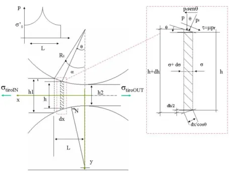
2.2.2 Distribution of roll stresses along the arc of contact
-“Slab Analysis”
With reference to Figure 2.2, let’s consider an infinitesimal vertical element in the arc of contact height h, thickness dx in the rolling direction and displaced between the point of entry to the rolling gap and the neutral point. pr is the
pressure acting between the surface of the roll and the strip on the ends of the worked element, pdxis the vertical force acting as y on the end of the element
and θ is the angle formed by the line joining the centre of the roll with the element and the vertical line.
If we assume that the width of the strip is uniform and that the rolls are rigid, the normal force acting on the end of the element is pr
dx
cos θ and its component onto the horizontal direction (opposing to the strip getting into the roll bite) is:
pr
dx
cos θ sin θ = pr tan θ · dx (2.1) Whereas the tangential friction force is µ pr
dx
cos θ, where µ is the coefficient of friction; the horizontal component of this force (dragging the strip in the roll bite) is:
µ · pr
dx
cos θ cos θ = µ · pr· dx (2.2) 8
2.2 Calculation of stresses distribution
Figure 2.2 – Unitary forces acting on the infinitesymal element object of study
The equilibrium ratio of the specified element leads to:
2 prdx tan θ − 2 µ prdx = (h + dh) · (σ + dσ) − hσ ⇒
2 prdx · (tan θ − µ) + hdσ + σdh = 0
(2.3)
which, rewritten, becomes:
pr(tan θ − µ) =
d(hσ)
2 dx (2.4)
If the element is displaced between the neutral point and the exit of the arc of contact, the equation 2.4 becomes:
pr(tan θ + µ) =
d(hσ)
2 dx (2.5)
combining 2.4 and 2.5 it becomes:
pr(tan θ ∓ µ) =
d(hσ)
2 dx (2.6)
Chapter 2 The cold rolling process hence p dx = pr dx cos θ cos θ = prdx (2.7) and 2.6 becomes: p(tan θ ∓ µ) =d(hσ) 2 dx (2.8)
From geometrical considerations:
1 2· dx dx = tan θ ⇔ dx = dh 2 tan θ (2.9)
so 2.8 can be rewritten in the form:
p( 1 2· dh dx∓ µ ) = d(hσ) 2 dx (2.10)
This differential equation, that can also be expressed in other equivalent forms, is known as Von Kármán equation, named after the researcher who first derived it in 1925. It represents the starting point for the analysis known as "theory of homogeneous deformation”
2.2.3 Solution of the Von Kármán differential equation
Several solutions to Von Kármán equation have been developed by researchers and can easily be found in mechanical engineering books or in rolling process specialized books (references to the study material are present in the bibliog-raphy); it must be said, anyway, that their main difference is in the friction forces assumption. To give an example, Von Kármán solution is based on the assumption of presence of dry slipping along the arc of contact and of a fric-tion force proporfric-tional to the value of normal local pressure (Coulomb fricfric-tion assumption: τ = µ pr).
A solution of Von Kármán equation is shown below.
Let us start by considering a condition of plasticity according to Von Mises 10
2.2 Calculation of stresses distribution yeld criterion1 , which is :
σ1− σ3= 2 √ 3σ0= σ ′ 0 (2.11) where: σ1= σ σ3= −p (2.12)
assuming that σ3 = −p , constant in the material, has value p on the axis
and is equivalent to the contact pressure. Therefore:
σ + p = σ0′ (2.13)
from which:
σ + p = σ′0⇒ dσ = −dp (2.14) Substituting this in 2.8 and recalling that dx = dh
2 tan θ, we get to the form:
h · dp −( µp tan θ+ σ ′ 0 ) · dh = 0 (2.15)
For the integral calculation, several relationships among h, θ and the abscissa x, need to be introduced.
This can be done by approximating the arc of contact by a parabola having the same curvature and the same tangent to the circumference of the roll,when x = 0.
h = h2+ 2 R0(1 − cos θ) ∼= h2+
x2
R0
(2.16) The approximation, written in terms of θ, can be expressed as:
h = h2+ 2 R0tan2θ = h2 ( 1 + R h2 tan2θ ) (2.17)
1Von Mises equivalent stress is σ 0 =
√1
2[(σ1− σ2)2+ (σ1− σ3)2+ (σ2− σ3)2] recalling
that in plane strain σ2= σ1+ σ3
2 ( direct as the axis of the cylinders) and substituting it in the previous one we get to the ratio
Chapter 2 The cold rolling process For convenience, we define:
tan ω =√ R h2 tan θ ⇒ h = h2(1 + tan2ω ) A = 2√ R0 h2 (2.18) By substituting 2.15 we have dp − (p µ A + 2 σ0′ tan ω)dω = 0 ⇒ dp − p µ A = 2 σ0′ tan ω dω (2.19)
Whose general integral, accepting the small-angle approximation, with tan ω ∼= ω, is p σ0′ = C e µ A ω − 2 A2 (1 + µ A ω) (2.20)
which gives the stress distribution along the arc of contact, between the neutral point and the exit section.
In the zone between the entry and the neutral point the equilibrium 2.15 is modified since the friction force changes its sign:
h · dp −(σ0′ −
µp tan θ
)
· dh = 0 (2.21)
After approximation, the general integral results in:
p σ0′ = C e
µ A ω− 2
A2 (1 − µ A ω) (2.22)
To calculate the constants we set boundary conditions, respectively
σ = σtiroOU T per θ = 0 ⇒ ω = 0 (2.23)
for the exit section, and:
σ = σtiroIN per θ = α ⇒ ω = ωα (2.24)
for the entry section 12
2.2 Calculation of stresses distribution Resolving it we get the distribution of stresses between the neutral point and the exit and entry sections. These are respectively:
p σ′0 = e µ A ω ( 1 + 2 A2 − σtiroOU T σ0′ ) − 2 A2 (1 + µ A ω) (2.25) p σ′0 = e µ A (ω− ¯ωα ( 1 + 2 A2(1 + µ A ωα) − σtiroIN σ′0 ) − 2 A2 (1 − µ A ω) (2.26)
If we draw a diagram of 2.25 and 2.25 we obtain the rolling stress distribution curve, generally known as “friction hill”, as shown in Figure 2.3; the pairs of curves meet in a point of no slipping, known as“neutral point” or “no-slip point”, which separates the pressure zone from the extrusion zone.
Figure 2.3 – Friction hill
Once the distribution of the stresses along the arc of contact is known, we can calculate the roll force and the torque:
FLaminazione= ∫ α 0 pR0dα (2.27) MLaminazione= ∫ α 0 µ pR0dα + R0(TOU T− TIN) (2.28)
where TIN= σtiroIN· h1 e TOU T = σtiroOU T · h2
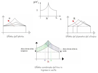
Equations 2.25, 2.26 e 2.27, once written in the explicit form, can be used to highlight the influence of various process parameters on the amplitude of the friction hill, hence on the roll force.
Chapter 2 The cold rolling process
Figure 2.4 – Influence of several parameters on the amplitude of the friction hill
It can be seen that the rolling force increases with an increase in the coeffi-cient of friction µ, in the radius of the cylinders and/or in pass draft (h1− h2)
and in the material strain hardening capacity. It, conversely, decreases when back and front tensions are applied to the rolling mill.
2.3 Cold rolling mills - a brief mention
The cold rolling process aims at reducing the workpiece thickness and at maintaining the strip width. There are two cold rolling methods: the first uses a series of several roll stands in sequence (tandem rolling mill), the other uses reversing mills.
In tandem cold rolling the process of strip cross-section reduction to its fi-nal thickness actually takes place in one pass through several mills in parallel alignment, as shown in Figure 2.5.
Tandem rolling mills are used in soft material rolling (mild steel, stainless steel, etc.) and they generally have a set of two, three or four mills (each set is called stand) depending on thickness reduction to be reached. There is a pay 14
2.3 Cold rolling mills - a brief mention
Figure 2.5 – Tandem rolling scheme
off reel at the entry of the mill and a take-up reel at its exit. Neutral rolls are displaced between the stands and the rolling speed is automatically adjusted as the workpiece passes from one stand to another.
Reversing mills are generally preferable to roll rolling different types of mate-rials; in this mills the direction of rolling is alternately reversed, the workpiece is passed forward and backward through the rolls (Figure 2.6).
Figure 2.6 – Reversible rolling mill scheme
The “Two High” reversing mill (2Hi) is the most elementary type of reversing mill. It consists of two working rolls put in a direct line (Figure 2.7) endur-ing the rollendur-ing force; the latter beendur-ing equally distributed on the support rolls which need to have big diameters as well. This arrangement uses high rolling forces and its application is limited to tight strips and controlled cross-section reduction operations (e.g. skin pass operations).
Chapter 2 The cold rolling process
Figure 2.7 – "Two High" cold rolling mill scheme
The most common type of reversing mill is the “Four High” reversing rolling mill (4Hi), consisting of four rolls, as shown in Figure 2.8.
Figure 2.8 – "Four High" cold rolling mill scheme
In this case, the two work rolls in direct contact with the workpiece are smaller than the external rolls (backup rolls), working as support rolls so that the rolling force is reduced; the relationship between the two external rolls and the work rolls may vary, ranging from 2:1 to 3,5:1, depending on hardness of work materials and cross-section reduction.
The advantages of this rolling mill arrangement are to be found in its simple structure and in the fact that no big rolling tensions are needed; conversely, due to the big size of the rolls, this type of rolling mill cannot be used for rolling too wide, too thin or too hard workpieces.
As for “Six High” reversing rolling mills, they can be of two types: the first, consisting of two work rolls and four external rolls (Figure 2.9), is not widely 16
2.3 Cold rolling mills - a brief mention used due to a non favourable distribution of the rolling force: and this although the horizontal force of the pair of work rolls is absorbed by the external rolls. The second widely used mill arrangement, consists of six high reversing rolls aligned on the same vertical axis, two work rolls, two intermediate rolls and two backup rolls (Figure 2.10).
Figure 2.9 – "Six High" cold rolling mill scheme, version 1
Figure 2.10 – "Six High" cold rolling mill scheme, version 2
2.3.1 Sendzimir reversing rolling mills
Sendzimir reversing rolling mills are of two types: "Z-High Mill", counting a total number of 18 rolls, and the "20-High Mill", where the number of rolls is 20.
Chapter 2 The cold rolling process Z-High mill
A scheme of a “Z-High Mill” is shown in Figure 2.11.
Figure 2.11 – "ZHi" Sendzimir rolling mill scheme
In order to reduce the diameter of the rolls the, “Z-High Mill” has lateral support rolls for the roll forces produced by the torque, in both rolling direc-tions. These rolls are not in direct contact with the work rolls but there an axial adjusting device right before the rolling process.
In order to face eventual problems at the edges of the strips, intermediate rolls, tapered on the end, are placed in direct contact with the work rolls. These rolls can be translated in their axial direction so to adjust planarity defects at the edges.
This type of rolling mill is an intermediate version between the “4Hi” and the “20Hi” rolling mill. It offers several advantages: the work rolls are smaller than those of a “4Hi” mill, hence, major cross-section reductions are possible; the roll force is vertical, unlike the “20Hi” mills, where it is instead distributed among all the rolls and rolls flattening plays an important role on strip forging, leading to the necessary construction of proper tempered rolls and of several adjustments; no need to use heavy tensions as in the “20Hi” mills; it can easily be converted into a “4Hi” mill.
A disadvantage can be traced in the size of the work rolls which are too big to allow further strip thickness reductions.
2.3 Cold rolling mills - a brief mention Multi-High mill
A "20-High Mill" is comprised of 20 rolls (Figure 2.12, Figure 2.13 e Fig-ure 2.14).
Figure 2.12 – "20 Hi" Sendzimir cold rolling mill scheme - whole mill
Figure 2.13 – "20 Hi" Sendzimir cold rolling mill scheme - upper half (rolls)
This type of rolling mill is characterized by very small sized work rolls (80-90mm diameter), through which large cross-section reductions, hard strips and
Chapter 2 The cold rolling process
Figure 2.14 – "20 Hi" Sendzimir cold rolling mill scheme - whole mill
very small thickness can be obtained.
The rolls are easy to replace and suitable to produce high surface quality strips. Thanks to the use of smaller work rolls, the flattening of the rolls does not play an important role in a numerical simulation study which allows to consider the rolls as rigid surfaces without making major errors, and the rolling forces are inferior; having many rolls in direct contact among them leads to the problem of shape defects, more precisely at the edges of the strip. The solution to this problem has lays in the use of tapered rolls which can move in the direction of their axis (Figure 2.15).
Another important characteristic of this type of rolling mills, which also represents the main difference between them and the 2Hi,4Hi and 6Hi mills, is the design of backup-rolls. In traditional rolling mills the rolls are backed-up at their edges by the rolling mill pillars, thus behaving like beams bearing 20
2.3 Cold rolling mills - a brief mention
Figure 2.15 – “Shifting” of first intermediate tapered rolls scheme
distributed loads, where the effect of rolls bending is relevant.
In Sendzimir rolling mills, backup rolls are bound not only at the edges but along the shaft. The external mill housing encloses the whole rolls. This is possible since the backup rolls are comprised of a shaft divided into sectors on which rolling elements bearing are placed and which, in turn, discharge the deformation on the whole cylinder block mill frame (Figure 2.16a). This results in the advantage of a mill which can be used both for wide and tight strips since it is the mill frame that is subject to deformation (Figure 2.16b), and still to a lesser extent in comparison to the rolls in traditional rolling mills.
(a) Scheme of a backup-roll (b) Rolling mill deformation
Figure 2.16
Torque transmission, necessary in the rolling process, takes place thanks to second intermediate motor rolls which, together with tensions applied to the take-up and pay off reels, enable the rolling process.
Chapter 3
Aluminium and its alloys
3.1 Introduction
Aluminium is a ductile metal mainly sourced from bauxite ore, an hydrated aluminium oxide containing from 50 to 60% of Al2O3 (alumina), from 1 to 20% of Fe 203 (haematite), from 1 to 10% of SiO2 (silica) and minor quantities of other minerals with an amount of water ranging from 20 to 30 %.
Raw aluminium is processed through industrial production processes, such as fusion, forging or stamping. Many industries use it for manufacturing a huge variety of products and it has a key role in the world’s economy. Structural components made of aluminium are essential for the aerospace industry and extremely important both in transport and construction fields where lightness of material, durability and resistance are key elements.
Figure 3.1 – Pure aluminium
Aluminium is a light metal with a silverly-white colouring (Figure 3.1) due to the light layer of oxidation which it develops when exposed to air and which
Chapter 3 Aluminium and its alloys
prevents corrosion, since it is insoluble. Aluminium has a specific weight of about a third of steel, or that of copper; it is malleable, ductile and easy to work. It has an excellent corrosion resistance and durability. Moreover, aluminium is non-magnetic and non-sparking , and it is the second most malleable metal and the sixth most ductile.
Aluminium is a chemical element included in the p- block metal group. It comes with the following general properties:
• Element with atomic number 13 and a face-centred cubic structure at room temperature;
• Electron Configuration: Ne3s23p1; • Density: 2,70 g/cm3;
• Melting point: 660° C;
• Ultimate tensile strength: 55 – 91 Mpa; • Modulus of elasticity: 66,6 GPa; • Elongation at break: 55;
• Low specific weigh; • High corrosion resistance;
• High thermal and electric conductivity; • Non- toxicity;
• High plasticity;
• Excellent ductility and malleability; • Low radiant power;
• Excellent weldability;
Aluminium alloys can be divided into two broad groups: casting alloys, used fot the production of casts, and wrought alloys, used for the production of rolled plates, forged components or extrudates. The latter, in particular, can conventionally be identified using their aluminium wrought alloys designation consisting of a four-digit number and a control acronym. The form of the designation is the following:
AAXXXXY
3.1 Introduction Where:
• AA stands for Aluminium Association;
• The first digit (X—) may range between 1 and 8 and indicates the prin-cipal alloying element;
• The second single digit (-X–),indicates a modification of the specific alloy, which is expressed by a 0;
• The last two digits (–XX) in the 1xxx series provide the degree of purity of aluminium, or minimum aluminium content. (For example, the alu-minium content of 1050 is 99.50%); in all the other series, the third and fourth digits are arbitrary numbers given to identify a specific alloy in the series.
Moreover, to designate the aluminium alloy, a final letter (Y) is added to the code, separated by a hyphen. This letter indicates the thermal and mechanical treatments the alloy may undergo to achieve its final properties, before usage. The temper designation letters have the following meaning:
• F - As Fabricated: no special control over the strain-hardening conditions • H - Strain hardened
• O - Annealed (tempering and recrystallization): The lowest strength, highest ductility temper
• W - Solution heat treated : applicable only to alloys which spontaneously age after solution heat-treatment
• T- Heat treated to produce stable tempers (other than F, O and H) Most aluminium alloys are normally supplied as semi-finished products, thus manufactured for plastic deformation processes.
Mechanical strength of the alloy can be increased through refinement and homogenization of grain and through material hardening resulting from ma-chining of the wrought alloy.
These alloys can be classified into two broad categories: non - heat treatable alloys, which can only be strengthened through cold working, and heat – treat-able alloys, which can be made stronger by precipitation hardening through
Chapter 3 Aluminium and its alloys coherent and semi-coherent phases.
3.2 Heat treatments
The main aluminium and aluminium alloys heat treatments are the following: • annealing
• relaxation
• solution treatment • precipitation hardening.
The term heat-treatment comprises all the cooling and heating operations executed on metal products, aiming at changing their mechanical properties, their specific metallurgical structure or their residual stress state.
When talking about aluminium, the application of the term is restricted since we refer to the specific operations employed in order to increase strength and resistance of alloys which can be hardened through precipitation hardening, thus generally referred to as “heat- treatable” alloys. Such mechanism consists in restricting dislocation movements the result of a proper distribution of par-ticles in the grains. The formation of grain-boundary precipitates needs to be avoided since a grain-boundary already represents a barrier to the movement of a dislocation.
A phase diagram containing a solubility curve which increases with an in-crease in temperature is an essential attribute for an alloy to be precipitation-hardened.
The typical heat treatment involves two stages known as solution treatment and aging.
Solution treatment is the heating of an alloy to a suitable temperature, hold-ing it at that temperature long enough to cause one or more constituents to enter into a solid solution and then cooling it rapidly enough to hold these constituents in solution. Subsequent precipitation heat treatments allow con-trolled release of these constituents either naturally (at room temperature) or artificially (at higher temperatures).
3.3 Main aluminium alloys Solution treatment: the alloy is heated above the solvus temperature in order to obtain an homogeneous solution, because the second phase which uses to be less, dissolves into the first one. The alloy is kept at this temperature until an homogeneous solution is obtained. The homogeneous solid solution it is then quenched at a cooler temperature where the conditions for supersaturation of the solution are reached.
Aging: a treatment used on alloys to develop their properties consists in controlled precipitation hardening treatment of very fine particles and is con-ducted both at room and high temperatures. In general, precipitation does not start immediately but it needs an “incubation time” to allow the formation of stable proper-sized nuclei; the growing process takes place right after.
The speed of precipitation varies depending on the temperature. With low temperatures, the speed of reaction is controlled by the velocity of migration of atoms. When performed at temperatures just below the solvus tempera-ture, the speed of precipitation is very low since the nucleation rate is slow. In this case, the solution is only lightly supersaturated and the precipitation is controlled by the atoms formation rate. When performed at intermediate tem-peratures, the speed of precipitation increases until it reaches the maximum speed, hence the time necessary for precipitation to take place is very short.
3.3 Main aluminium alloys
With respect to the first figure in the code, we distinguish:
• 1xxx Series alloys: the pure aluminium series comprised of 99% minimum aluminium. Alloys characterized by excellent corrosion resistance, high thermal and electrical conductivity, good workability and relatively poor mechanical properties.
• 2xxx Series alloys: principle alloying element is copper. These are heat-treatable alloys.
• 3xxx Series alloys: the major alloying element used is manganese which allows both to increase the mechanical strength of wrought alloys and to
Chapter 3 Aluminium and its alloys
reduce their sensitivity to intergranular corrosion and stress corrosion. • 4xxx Series alloys:silicon is the used as principle alloying element which,
when added to aluminium, improves its fluidity and and reduces its melt-ing pot.
• 5xxx Series alloys: magnesium is the major alloying element which gives the alloy special properties of resistance to corrosion in addition to good levels of resistance to heat, excellent ductility and workability. It gener-ally does not require age hardening and possesses good weldability. • 6xxx Series alloys: Silicon and magnesium are the two major alloying
elements. These are heat-treatable alloys which, after heat-treatment, develop intermediate mechanical properties, although generally inferior to the 2000 series alloys. They have good formability, good workability, as well as good machinability and weldability. This series alloys are the most widely used for heat-treated workpieces and for those obtained by fusion. They combine some favourable properties: good mechanical strength, relatively low sensitivity to hardening and good resistance to corrosion. • 7xxx Series alloys: the principle alloying element is zinc, which has a
higher solubility than aluminium. Binary Al- Zn alloys are generally not used, Al-Zn-Mg alloys are preferred. These are heat-treatable alloys which develop the highest mechanical properties among all aluminium alloys. Zinc addition increases resistance and hardness besides fostering self-hardenability of the alloy.
• 8xxx Series alloys (miscellaneous compositions): among these, Al -Li al-loys are very important (i.e. 8090) characterized by low density (2,5-2,6g/cm3 depending on the percent of lithium contained in the alloy) and good resistance to stress, they maintain good static resistance, also after impact damage, and excellent toughness, even at low temperature. They are distinguished by good workability to machine tools and, in most cases, poor fusion weldability. These alloys are widely used for building aeronautic structures and for the construction of means of transport and of all parts subjected to great stresses, in general.
3.3 Main aluminium alloys The alloys involved into the study merit a more in-depth analysis: 5182, 5754 and 6016 alloy.
3.3.1 AA 5182 alloy
The AA 5182 aluminium alloy belongs to the 5000 series alloys containing a high magnesium content, it is annealed and crystallized. The following table will provide its chemical composition [3, 4]:
Table 3.1 – AA5182 alloy chemical composition Material Percentage [%] Aluminium, Al 93.2 ÷ 95.8 Chromium,Cr 0.10 Copper, Cu 0.15 Irone, Fe ≤ 0.35 Magnesium, Mg 4.0 ÷ 5.0 Manganese, Mn 0.2 ÷ 0.5 Silicon, Si ≤ 0.20 Titanium, Ti ≤ 0.10 Zinc, Zn ≤ 0.25 Other, each ≤ 0.05 Other, total ≤ 0.15
Traditionally used in aeronautics, for the construction of welded structures, the aluminium-magnesium 5182 alloy is characterized by excellent resistance properties to oxidation and corrosion in general; its mechanical properties are extremely high, its formability is also very high and it can be readily fusion welded. This alloy exhibits excellent toughness both at room and low temper-atures.
It is widely used in trim panels, pressure vessels, lorries, road tankers, fuel tanks, as well as in ship structures, plates, wheels, cryogenic applications and, in general, in all applications not requiring very high static mechanical properties but good fatigue resistance.
Chapter 3 Aluminium and its alloys
Table 3.2 – Main physical properties of AA5182 alloy at room temperature ρ [g/cm3] 2.650
k [W/mK] 126 Cp[J/gK] 0.904
E [M P a] 69.600
Table 3.3 – Main processing properties of AA5182 alloy Formability Very good at O/H111 temper Machinability on tool machines Not good
Weldability Good (TIG - MIG)
Corrosion resistance Good
3.3.2 AA 5754 aluminium alloy
The AA 5754 aluminium alloy belongs to the 5000 series alloys containing a high magnesium content, it is annealed and crystallized. Its chemical compo-sition is the following [3, 4]:
Table 3.4 – AA5754 alloy chemical composition Material Percentage [%] Aluminium, Al 93.6 ÷ 97.3 Chromium,Cr 0.30 Copper, Cu 0.10 Cr + Mn 0.10 ÷ 0.60 Iron, Fe ≤ 0.40 Magnesium, Mg 2.6 ÷ 3.6 Manganese, Mn ≤ 0.50 Silicon, Si ≤ 0.40 Titanium, Ti ≤ 0.15 Zinc, Zn ≤ 0.20 Other, each ≤ 0.05 Other, total ≤ 0.15
The aluminium – magnesium 5754 alloy is characterized by excellent resis-tance properties to oxidation and corrosion in general; its mechanical properties are poor, its formability is instead very high and it can be fusion welded. The alloy is generally used in the form of thin plates. It is moreover widely used for the construction of trim panels, pressure containers, lorries, road tankers, chemical plants and ship structures, as well as of plates, wheels and applica-30
3.3 Main aluminium alloys tions not requiring very high mechanical properties. It is often used for the insertion of single elements to welded structures.
Table 3.5 – Main physical properties of AA5754 alloy at room temperature ρ [g/cm3] 2.650
k [W/mK] 138 Cp[J/gK] 0.213
E [M P a] 70.000
Table 3.6 – Main processing properties of AA5754 alloy Formability Very good at O/H111 temper Machinability on tool machines Not good (better at H32 temper)
Weldability Good (TIG - MIG)
Corrosion resistance Good
3.3.3 AA6016 aluminium alloy
The AA6016 aluminium alloy belongs to the 6000 series alloys containing a high silicon and magnesium content, it is annealed and crystallized. Its chemical composition is the following [3, 4]:
Table 3.7 – AA6016 alloy chemical composition Material Percentage [%] Aluminium, Al 96.4 ÷ 98.8 Chromium,Cr 0.10 Copper, Cu 0.20 Iron, Fe ≤ 0.50 Magnesium, Mg 0.25 ÷ 0.60 Manganese, Mn 0.20 Silicon, Si 1.00 ÷ 1.50 Titanium, Ti ≤ 0.15 Zinc, Zn ≤ 0.25 Other, each ≤ 0.05 Other, total ≤ 0.15
Traditionally used in the fields of aerospace, railways and shipbuilding for welded structures, the 6016 aluminium-magnesium-silicon alloy exhibits excel-lent resistance to oxidation and corrosion in general. It has good mechanical
Chapter 3 Aluminium and its alloys
properties although inferior to the 2000 and 7000 series alloys; good machin-ability on machine tools and high formmachin-ability: it is moreover fusion weldable.
The alloy is used in architectural applications, motorcycle and bicycle looms, welded structures in general. This system constitutes the main series of alloys used for hot-processed and merged components.
The 6016 alloy has recently been introduced into the automotive sector with regard to the application of stamped sheet metal components (car body and external panels).
Table 3.8 – Main physical properties of AA6016 alloy at room temperature ρ [g/cm3] 2.700
k [W/mK] 190 ÷ 210 Cp[J/gK] 0.869
E [M P a] 68.900
Table 3.9 – Main processing properties of AA6016 alloy Formability Very good at T4 temper Machinability on tool machines Good
Weldability Good (TIG - MIG)
Corrosion resistance Good
3.4 Hybrid aluminium composites
A hybrid matrix composite combines more than two kinds of matrix, such as a metal and a polymer.
In a polymer metal sandwich construction the matrix is formed by metal sheets and a polymer honeycomb structure which is fibre-reinforced as shown in Figure 3.2.
Polymer metal sandwich sheet composites are made from a polymer honey-comb structure enclosed by two thin metallic sheets. A resin or adhesive is used as a matrix, which holds it all together. The honeycomb structure makes the composite relatively light, but stiff.
3.4 Hybrid aluminium composites
Figure 3.2 – Aluminium hybrid composite
Examples of polymer metal sandwich sheets are Hylite, which is made of two thin aluminium layers with a plastic (polypropylene/PP) core in between, and Dibond, which is similar to Hylite, but in which the polypropylene is substituted with polyethylene.
3.4.1 DIBOND®
DIBOND®combines 0.3mm Aluminium layers on either side with a Polyethy-lene core. The light weight sheet material can be transformed three dimension-ally by using the routing and folding technique but it is stiff and stable at the same time, ideal for indoor as well as outdoor applications.
Figure 3.3 – DIBOND®layers detail
DIBOND®has a very low thermal expansion and is weather resistant: it is applicable with temperatures between -50°C and +80°C.
Chapter 3 Aluminium and its alloys Common applications:
• Indoor and outdoor signage • Shop fronts
• Exhibition design
• Shop fitting - Shop design - Furniture design • Displays - POS/POP
The main process techniques are:
Table 3.10 – DIBOND®processing
Cutting Sawing
Contour cutting Contour milling
Drilling Punching
Shearing Fettling
Routing Folding
Glueing Bending
Screwing Riveting
Clamp connections Hot air welding
3.4.2 HYLITE ®
HYLITE®is an aluminium composite panel with a polypropylene core and aluminium outer skins. Two different core systems were tested.
Compact CORE - Panel thicknesses 1.2 mm and 2 mm
HYLITE®Compact CORE is the world’s thinnest composite panel with thick-nesses of 1.2mm and 2mm, and it offers another special feature: the panel’s core material can provide a hinge function, which withstands repeated bend-ing without damage. This function is achieved by millbend-ing grooves in the same position into both outer aluminium skins.
Common applications include:
• Office articles - article design e.g. high-end CD sleeves, files and books backs etc.
• Technical manuals for automotive industry • Notebook stands
3.4 Hybrid aluminium composites
Figure 3.4 – HYLITE®layers detail
• Bicycle mudguards • High-end packaging • Suitcases
Foamed CORE - Panel thicknesses 3 mm and 4 mm
The core material for the 3mm and 4mm - panel thicknesses - is foamed in a thicknesses manufacturing process specially developed for this purpose. The result is an ultra-light aluminium composite panel, and the only cutback is in weight: HYLITE®in 3mm and 4mm thicknesses is up to 80% lighter than conventional steel sheets or up to 60% lighter than aluminium sheets yet provides the same flexural rigidity.
The foamed core panel features other superlative technical properties. Major advantages include dimensional stability at high temperatures and excellent digital printing results, due to the high quality aluminium strips used in the production process.
Common applications include:
• Interior / exterior cladding for commercial vehicles, agricultural machin-ery, mobile homes, caravans, buses, trains
Chapter 3 Aluminium and its alloys • loudspeaker casings
• Furniture design • Signs / advertising • Light boxes
Moreover HYLITE®has dimensional stability at temperatures ranging from +120°C to , for a limited period, +150°C (approx. 30 minutes). It can also be processed in plenty of ways:
Table 3.11 – HYLITE®processing
Cutting Roll bending
Sawing Folding
Drilling Punching
Gluing Profile milling Riveting Screen printing Screwing Direct digital printing
Bending Embossing
Contour cutting Water jet cutting Powder coating Hinge joint routing
Chapter 4
Characterisation of materials
4.1 Introduction
The rolling process, also known as sheet-metal forming, using the Anglo-Saxon terminology, has acquired a dominant position in several fields of me-chanics, such as the automotive and the aerospace industries. Of course, the tendency is to obtain, also in mass production, excellent quality finished prod-ucts and to reduce scraps resulting from breaking, surface defectiveness or exceeding the Geometric Dimensioning & Tolerancing (GD&T) limits. In this scenario, the need to manifacture semi-finished products or finished parts char-acterised by a low index of scraps coming from procedural errors or surface defects, has given the impetus to several experimental, theoretical and numer-ical analyses of sheet-metal forming.
The capability of a workpiece to survive a bulk deformation process (i.e. forging) can be described as workability, which takes into account both the ductility of the worked material and the stress-rate enforced by the process; in this case fracture is a major concern. Conversely, the capability of a workpiece to survive sheet-metal working processes, is linked to the concept of formability, another complex property which is strictly related to causes of failure during the rolling process; some of them will be mentioned below.
During rolling, the surface of the worked material can appear “grainy” and show an “orange peel” effect. This is a natural consequence of the
polycrys-Chapter 4 Characterisation of materials
talline structure of metals. In fact, each grain has a crystallographic direction which distorts in a slight different way from the others. This effect has no backwash on the integrity of the structure but it may be aesthetically unac-ceptable. This problem can be avoided by using materials characterized by very tiny grains so that the effect would be invisible to the naked eye. In some work materials the yield stress can be highly localized and visible on the surface in the form of slip bands (Lüders bands). As the deformation process advances, the surface of the workpiece will be crossed by families of these slip bands which are harmless, as far as resistance is concerned, but intolerable on exposed surfaces. However, once the whole surface of the workpiece is covered with bands, they are not distinguishable any more.
In the case of localized necking, both aesthetics and functional properties are involved; although there is no fracture, the local material load resistance could be reduced, the other sections will still remain perfectly functional. The choice of materials is intended to optimize those factors capable of delaying the onset of the necking process or of redistributing the incipient necking. Once necking is triggered off, a subsequent plastic deformation will produce a localized thickness reduction up until fracture. In cold metal working, an even low yet positive value ofm (strain rate sensitivity exponent) can be useful.
Many alloys are suitable for sheet-metal working treatments.
Of course, these alloys need to have sensibly different properties from those required to metals used in bulk deformation, not only because this type of defor-mation results from the application of tensile stresses, not compression, but also because the work elements in the rolling mill are mostly exposed parts; hence their finishing needs to be faultless. It is therefore necessary to use sheet-metal characterization criteria which overcome the mere mechanical characterization (determination of flow curves, determination of the strain sensitivity index and of the strain-rate sensitivity index, definition of hardness, etc.) to get to the heart of the forming process; in other words, it is necessary to investigate the “formability” properties of the material [5]. A powerful formability assessment tool is represented by the Forming Limit Curve (FLC) [6] which expresses the limit condition to the main real in-plane strains in sheet-metal forming (ε1,
4.1 Introduction ε2), once the limit condition is passed, undesired fracture or necking
phenom-ena take place. Thanks to this knowledge, the effects of enforced strains can be predicted and the setting of a forming process based only on empirical con-siderations or on “trial and error” methods, can be avoided. For this reason, the FLC is a very useful element in the planning phase and control phase of the forming process. There are several standard and non-standard tests which aim at defining and evaluating the formability of sheet-metals (the Erichsen test, the Nakazima test, the Marchiniak test, etc.). Among these tests, the Nakazima test, simulating the behaviour of a planar strain deformation of a sheet-metal under real process conditions, is the most targeted at determining the FLC.
Formability testing inevitably necessitates a considerable strain on resources, as well as the application of sophisticated strain analysis and strain measure-ment techniques. It is mainly for these reasons that research for the defini-tion of the FLC is mostly conducted under controlled laboratory condidefini-tions. Experiment-based research has recently been supported by sophisticated nu-merical techniques grounded on analytical approaches to the problem of sheet-metal plasticity. These numerical techniques can be used as a modern analysis tool to obtain formability parameters of sheet-metals in a less time-consuming and more cost-effective way. To give an example, significant developments made in the calculation codes based on the finite element method (FEM), sug-gested the possibility of simulating formability tests on the computer with a consequent drastic reduction in the time and equipment necessary to obtain an operational assessment of formability. This makes the FLC analysis process much more direct and immediate, and therefore applicable also to contexts where not all the necessary equipment for experimental testing is available. Of course, a similar approach needs to undergo a preliminary testing phase before being for its assessment.
Chapter 4 Characterisation of materials
4.1.1 Formability
The term refers to the different types of sheet-metal forming processes a workpiece can be subject to. These processes, in case of complex shapes, may vary depending on the parts of the workpiece taken into consideration.
Bending is one of the basic types of sheet-metal forming; in this case, the deformation takes place only in the area of the workpiece where forces are applied modifying its bending radius. In bending, the typical strain state, corresponds to the existence, on the plane of the sheet, of an in-plane strain direction coincident with the bending axis.
In stretching (or stretch-bending), only a specific region of the metal-sheet undergoes deformation, the remaining part is, instead, totally clenched by a blankholder acting in the region surrounding the strained area. The form-ing process may be carried out through direct action of a pressurised fluid ( hydroforming process), in this case no friction phenomena are present on the stretched area; it can, otherwise, be performed by a punch pressed into the workpiece with force (punch stretching), in this case, friction phenomena between the surfaces of the elements in contact produce effects of major impor-tance on the process. The typical strain state in this type of forming process is distinguished by the fact that the two main in-plane strains are both positive. The deep drawing process produces a deformation state characterized by the existence of a main drawing direction, on the plane of the sheet, along which the deformation is positive, and of a second drawing direction, along which the deformation is negative. The reduction in the blank planar perimeter (circum-ferential compression), visible in a drawing operation, is a most evident example of this. In this case, the compressive strength has an impact on the workpiece formability, especially when the blank undergoing the process is clenched only on one side or not clenched at all by blankholder and die. The circumferential compression resulting from blank perimeter reduction, causes the formation of wrinkles, ending in the discarding of the piece. In industrial sheet-metal forming processes, these basic types of deformation are used, separately or simultaneously, with a general predominance of tensile stress states.
![Table 3.2 – Main physical properties of AA5182 alloy at room temperature ρ [g/cm 3 ] 2.650](https://thumb-eu.123doks.com/thumbv2/123dokorg/2968033.27072/54.892.309.561.633.881/table-main-physical-properties-aa-alloy-room-temperature.webp)