David Perillo
Modelling and Simulation
of Embedded Systems
with Formal Languages
and Virtual Platforms
D265ModTPhD/EN00
Phd Course Emerging Digital TechnologiesAccademic Year
2013-2014
ISBN: XXXXXXXXXXXXModelling and Simulation
of Embedded Systems
with Formal Languages
and Virtual Platforms
Author
David Perillo
Supervisor
Scuola Universitaria Superiore
Sant’Anna Pisa
Doctoral Thesis
Modelling and Simulation of
Embedded Systems with Formal
Languages and Virtual
Platforms
Author:
David Perillo
Supervisor:
ii
A thesis submitted in fulfillment of the requirements
for the degree of Doctor of Philosophy
in the
Tecip Institute
Retis Laboratory
iii
Declaration of Authorship
I, David Perillo, declare that this thesis titled, “Modelling and Simulation of Embedded Systems with Formal Languages and Virtual Platforms” and the work presented in it are my own. I confirm that:
• This work was done wholly or mainly while in candidature for a research degree at this University.
• Where any part of this thesis has previously been submitted for a degree or any other qualification at this University or any other institution, this has been clearly stated.
• Where I have consulted the published work of others, this is always clearly attributed.
• Where I have quoted from the work of others, the source is always given. With the exception of such quotations, this thesis is entirely my own work. • I have acknowledged all main sources of help.
• Where the thesis is based on work done by myself jointly with others, I have made clear exactly what was done by others and what I have contributed myself.
Signed: Date:
v
“The limits of language are the limits of the world. It will therefore only be
in language that the limit can be drawn, and what lies on the other side of the limit... will simply be non-sense.”
vii
Scuola Universitaria Superiore Sant’Anna Pisa
Abstract
TeCIP Institute Retis Laboratory
Doctor of Philosophy
Modelling and Simulation of Embedded Systems with Formal Languages and Virtual Platforms
by David Perillo
Embedded Systems pervade almost every aspect of our society and our interactions with devices and other human beings, improving the quality of life, and even protecting human lives in safety-critical situations.
The Industrial approach to the design, realization, technical management, operations, and retirement of a system, is technically referred to as System Engineering (SE). The standard approach to SE relies on documents written in natural language as the primary source of information. In the domain of hardware-software (embedded) systems the integration, Verification and Validation (IV&V) activities, which are in charge of checking that the system is correct and performs its intended functions, are usually performed after the hardware platform has been deployed (post-silicon stage).
Modern trends in SE promote the use of model-based solutions for collecting customer and stakeholder needs, design and verification rules, and the implementation constraints. Compared to standard SE, the Model-Based approach (MBSE) enforces the requirements validation by means of model-checking. As a consequence, MBSE reduces the project-rework caused by poorly defined requirements and attempts at removing design-level errors.
Even though a great effort has been put in recent years to pursue the Industrial application of MBSE, the common Industrial practice still relies on standard SE design workflows. This is mainly due to the high costs of managing the MSBE workflows complexity, and to the attitude of System Engineers to reject formal modelling languages in favour of code and natural language documents with ad-hoc pictures and diagrams.
The purpose of this Thesis is to boost the industrial adoption of MBSE by providing a measurable and profitable Return On Investment (ROI), and by narrowing the existing gap between structural and simulation models. The goals of this research are:
• to assess the language constructs required to describe complex HW/SW architectures;
viii
• to realize a joint co-design and co-verification workflow for real-time embedded systems;
• to enhance system-level Design Space Exploration (DSE) by means of a purposedly developed design and simulation framework.
The proposed workflow is implemented by a Model Driven Architecture (MDA) framework composed of metamodels, automatic model transformations and full-system simulation tools. The system simulation has been realized both with the WindRiver Simics and with the QEmu open-source Instruction-Set Simulator (ISS). The DSE is performed with a Platform Based Design (PBD) approach, which is a consolidated design methodology for Electronic System Level (ESL) design. The formal languages used to perform the MBSE workflow are SysML, enhanced by the MARTE profile, and Arcadia, which is an emerging implementation of the SysML standard enriched with Electronic-Systems Design (ESD) and NATO Architecture Framework (NAF) standard constructs.
ix
Acknowledgements
Firstly, I would like to express my sincere gratitude to my advisor Prof. Marco Di Natale, for the continuous support of my Ph.D study and related research, for his patience, motivation, and immense knowledge. His guidance helped me in all the time of research and writing of this thesis. I could not have imagined having a better advisor and mentor for my Ph.D study.
Besides my advisor, I would like to thank the rest of my thesis committee: ... , for their insightful comments and encouragement, but also for the hard question which incented me to widen my research from various perspectives.
A Special thank goes to the Elettronica SpA company, who immensely supported me along this crucial path. Mrs. Daniela Pistoia, Mr. Francesco Chirico, my colleagues Antonio Rabbia, Alessandro Bazzoni, Federico Fazi, Francesco De Cardona.
This thesis was conducted through many fruitful interactions with Thales and Elettronica. Many ideas leading to the contributions presented here on the Arcadia Methodology emerged from continuous interactions with Jean-Luc Voirin, Eric Lepicier, Francois Benoit, Harnaud Hidler,... to whom goes my sincere gratitude for having directly supported my research activity.
xi
Contents
Declaration of Authorship iii
Abstract vii
Acknowledgements ix
Summary
1
1 Introduction 1
1.1 Electronic Defense Systems. . . 2
1.2 Software Firmware Co-simulation . . . 3
1.3 Platform Based Design . . . 5
1.4 Thesis Outline . . . 7
2 Methods and Tools for Design and Simulation of Embedded Systems 9 2.1 Model Driven Architecture . . . 9
2.1.1 Model To Model Transformations . . . 10
2.1.2 Model To Text Transformations . . . 11
2.1.3 UML . . . 11
2.1.4 The MARTE UML Profile . . . 12
2.2 Model Based System Engineering . . . 13
2.2.1 SysML . . . 13
2.2.2 Arcadia . . . 13
2.3 Frameworks for SW/FW Co-simulation . . . 15
2.3.1 Synchronous Reactive MoC . . . 15
2.3.2 Instruction Set Architecture Simulators . . . 15
2.3.3 Virtual Platforms . . . 16 2.3.4 Simics . . . 16 2.3.5 QEmu . . . 16 3 Summary of Research 17 3.1 Research Objectives . . . 17 3.2 Papers Summary . . . 19
3.2.1 Paper 1: Using MDA to Automate the Integration of Virtual Platforms for System-Level Simulation . . . 19
xii
3.2.2 Paper 2: Extending QEmu to support Design Space
Exploration . . . 19
3.2.3 Paper 3: Arcadia and SysML comparison for MBSE and PBD . . . 20
4 References for the Summary 21
Paper 1: Using MDA to Automate the Integration
of Virtual Platforms for System-Level Simulation
23
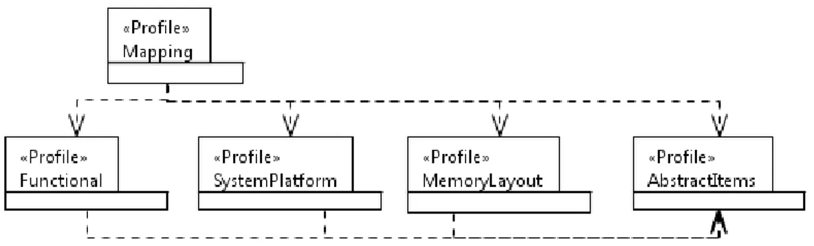
5 System Modelling 25 5.1 Profile architecture . . . 255.2 Hardware-software interface Profile . . . 26
5.3 Functional Profile . . . 27
5.4 System Platform Profile . . . 28
5.5 Mapping profile . . . 29
5.6 Case Study . . . 32
5.6.1 Running Example . . . 32
5.6.2 Case study: functional modelling . . . 33
5.6.3 Case study: System level Platform modelling . . . 33
5.6.4 Case study: Mapping model . . . 34
6 Design Space Exploration with the Simics Virtual Platform 35 6.1 System Level Synthesis . . . 35
6.1.1 The Complex Framework. . . 37
6.2 Extending the Simics Full System Simulator . . . 38
6.3 Glue Code generation for the Simics simulation elements . . . . 40
The .simics configuration file . . . 40
6.3.1 Synchronous reactive glue code . . . 40
6.4 Results . . . 43
Paper 2: Design Space Exploration with QEMU
45
7 Extending QEmu to support Design Space Exploration 46 7.1 Introduction . . . 467.2 Context and Positioning . . . 47
7.3 Extending the QEMU Virtual Platform . . . 49
7.4 The QEMU device language . . . 52
7.4.1 QDL data structures . . . 52 7.4.2 Simulated Device . . . 53 7.4.3 Memory Layout . . . 53 7.4.4 Memory Bank . . . 54 7.4.5 Group of Registers . . . 55 7.4.6 Register . . . 57 7.4.7 Field . . . 59
xiii
7.4.9 QDL API . . . 60
7.5 Code complexity of QDL . . . 62
7.6 Case Study . . . 63
Paper 3: Arcadia for MBSE and PBD
69
8 Arcadia and SysML comparison for MBSE and PBD 70 8.1 SysML . . . 708.2 Arcadia . . . 70
8.3 Platform-Based Design . . . 71
8.4 Running Example . . . 71
8.5 Emerging differences amid Arcadia & SysML . . . 72
8.5.1 Requirement tracing and Justification Links . . . 72
8.5.2 Elements creations and replication . . . 72
8.5.3 Domain Specific metamodel . . . 73
8.5.4 Modelling Perspectives (View Points) . . . 73
8.5.5 Physical to Functional deployment . . . 74
8.6 The Arcadia’s Physical Architecture . . . 75
8.6.1 Data Types . . . 75
8.6.2 Modes & States . . . 75
8.6.3 Structural elements . . . 78
8.6.4 Functional elements . . . 79
8.6.5 Scenario . . . 81
8.6.6 Functional-Chains. . . 82
8.7 Capability Realization and Engineering Plan . . . 82
8.8 Physical model: SysML and Arcdia . . . 83
8.8.1 Mapping vs Deployment . . . 83
8.9 Considerations on the Arcadia Methodologies . . . 84
8.9.1 Industrial adoption of Arcadia . . . 84
8.9.2 Deployment approach. . . 85
Final Considerations and Future Directions
87
9 Papers Conclusions 88 9.0.1 Paper 1: Using MDA to Automate the Integration of Virtual Platforms for System-Level Simulation . . . 889.0.2 Paper 2: Extending QEmu to support Design Space Exploration . . . 88
9.0.3 Paper 3: Arcadia and SysML comparison for MBSE and PBD . . . 89
10 Contributions to Research Objectives 90 10.0.1 Contribution to R1 and R2 . . . 90
10.0.2 Contribution to R3 . . . 90
10.0.3 Contribution to R4 . . . 90
xiv
11 Future Directions 91 11.1 Fault-Injection and Reliability Assessment . . . 91 11.2 Robust Functional Integration with an Hybrid Test Bench . . . 91 11.3 Measuring Consistency amid VP and real HW . . . 92
xv
List of Figures
2.1 M2M . . . 11
5.1 Profile architecture . . . 25
5.2 Hardware-Software Interface Profile Elements . . . 26
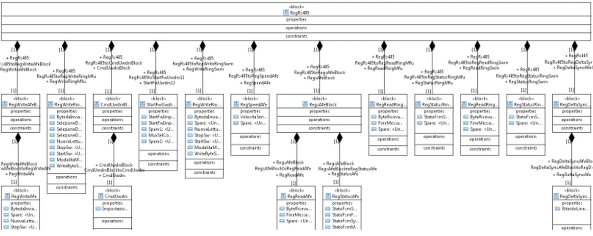
5.3 RS485 . . . 26
5.4 Functional Profile Elements . . . 27
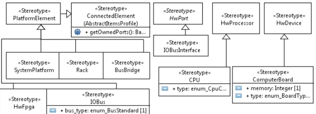
5.5 System Profile Elements . . . 28
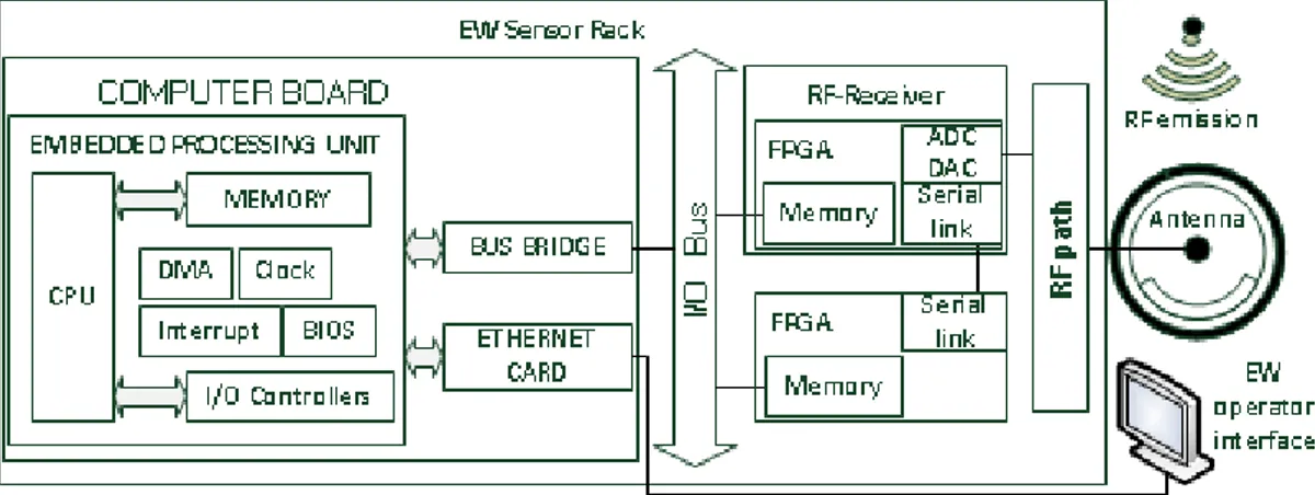
5.6 EW sensor main elements . . . 29
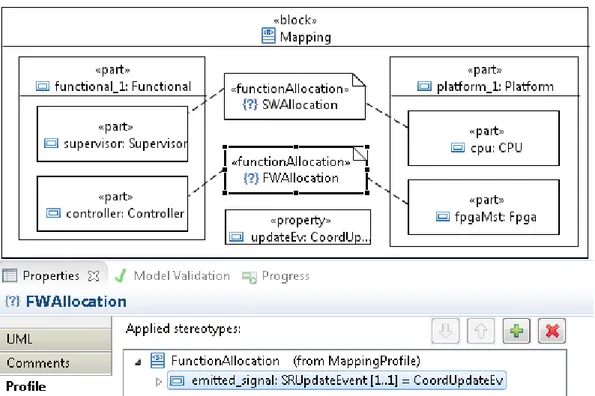
5.7 Mapping profile . . . 29
5.8 The allocation of the functional subsystems onto the computing HW . . . 30
5.9 Row Data Table . . . 31
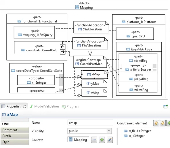
5.10 Mapping ports and data types . . . 31
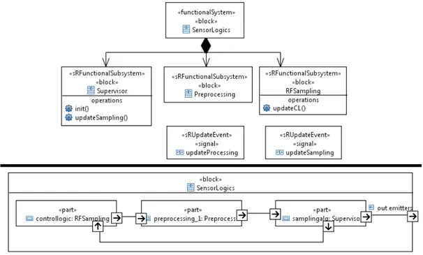
5.11 Functional (BDD and IBD) models of the RWR . . . 33
5.12 System Platform BDD and IBD of the RWR . . . 33
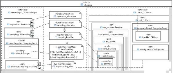
5.13 RWR Mapping Model . . . 34
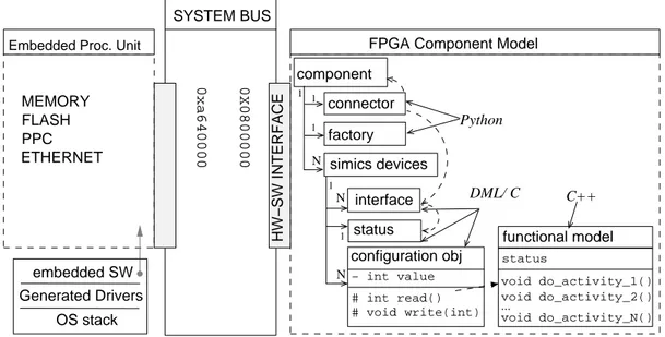
6.1 Simics component models of FPGA and Embedded Processing Unit. The application software runs on the PPC ISA. . . 39
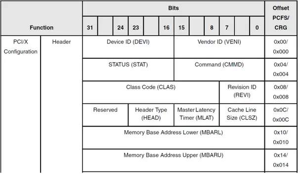
7.1 PCI Configuration Space(PCFS) implemented in any PCI device to interact with the OS Kernel . . . 48
7.2 Memory management in QEMU . . . 49
7.3 QDL structures diagram . . . 52
7.4 Registers instances stored in an array of values . . . 57
7.5 Read transaction propagation along QDL objects . . . 61
7.6 TSI 148 Configuration space . . . 63
7.7 TSI 148 Configuration space . . . 64
7.8 TSI 148 Windows and devices . . . 64
8.1 a purposely simplified RWR consisting of a Passive Antenna Unit (PAU), a Sensor and Processing Unit (SPU) and a Console. . . 72
8.2 Connections between Boxes in PA . . . 74
8.3 SysML final deployment . . . 75
8.4 Arcadia Metamodel Ontology and modelling perspectives. The diagram represents three main kind of elements: Boxes, represented with double line rectangles; Connectors, with ovals and Ports with solid line rectangles. Arrows represent realization. 76 8.5 Data Types . . . 77
xvi
8.6 Arcadia Modes & States diagrams . . . 77
8.7 RWR Physical decomposition . . . 78
8.8 Actors and Physiscal Path . . . 79
8.9 Functional architecture with Arcadia DFD . . . 80
8.10 Functional architecture with SysML BDD and Class diagram . . 80
8.11 Arcadia Scenario diagrams . . . 81
8.12 SysML profile used for the PBD example model . . . 83
xvii
List of Abbreviations
API Application Programmer Interface ASIC Application Specific Integrated Circuit DSE Design Space Exploration
EDA Electronic Design Automation FPGA Field Programmable Gate Array FW Firmware
HW Hardware
ISA Instruction Set Architecture ISS Instruction Set Simulator
IV&V Integration, Verification & Validation MBSE Model Based System Engineering MDA Model Driven Architecture
MoC Model of Computation PBD Platform Based Design SE System Engineering SPS Self Protection Suite
SysML System Modelling Language SW Software
xix
1
Summary
1. Introduction
Embedded systems are characterized by computer architectures, in which highly-integrated platform and functional components perform specific capabilities within a larger system. Platform components include multi-layer heterogeneous hardware (HW) architectures composed of Computer Boards (including CPU, Memory and communication adapters), Application Specific Integrated Circuits (ASICs), Field Programmable Gate Arrays (FPGAs) with their interconnects, such as buses, communication networks and serial links, and the basic sowftare managing them, with the Operating System (OS), the drivers, and the communication stack. The Functional components implement tasks and activities to realize system-level Capabilities, often characterized by real-time constraints. The Functional components associated to demanding hard-real-time execution constraints (deadlines of few microseconds) are typically synthesized in FPGAs and identified as firmware (FW). The Functional components with more relaxed constraints (deadlines of few milliseconds) are implemented as application software (SW), which runs on Computer Boards and manages FW and ASICs devices.
The realization of such a complex system architecture is a multidisciplinary endeavor encompassing specifications, design, implementation and validation activities, which is referred to as System Engineering (SE).
In the classical Waterfall process for embedded systems design, the user needs are firstly gathered and converted to System specifications, and then partitioned among Physical and Functional components for the detailed design and its implementation, which is performed by specialized teams. According to the Vee System Engineering process model (Dickerson and Mavris, 2016), which is a specialization of the Waterfall process, the high-level system specifications are traced down to low-level Platform and Functional components, which are verified independently before being integrated and verified on the whole System. If the SE process is performed with a
2 Chapter 1. Introduction
model-centric approach, the verification process can benefit from the same models used for the design. The paradigm shift introduced in SE by the use of models, referred to as Model Based System Engineering (MBSE), allows a requirement-driven and architecture-centric approach to SE, where different viewpoints on the same model are used to capture customer and stakeholders needs, design solutions, validation rules and implementation constraints. In its 2020 vision for System Engineering (incose_2020), INCOSE defined MBSE as the formalized application of modeling to support system requirements,
design, analysis, verification and validation activities beginning in the conceptual design phase and continuing throughout development and later life cycle phases. In other words, the proposed the MBSE Onthology strictly relies
on the structured use of models to accelerate high-level system design. Conversely from the traditional document-centric approach, which relies on requirements expressed in natural language, it enhances the possibility to validate requirements against inconsistency and reduce project re-work caused by inconsistent or poorly defined requirements. MBSE is supported by international standards DO-178C/DO-331, as an approach to improve Verification and Validation (V&V) quality processes(Eisemann, 2016).
The goal of this Ph.D. Thesis is to present existing solutions for embedded systems design, and to propose an Industrial approach to detect functional interaction issues in the very early design stages. Although the examples in this Thesis are specific for Electronic Defense systems (described in Sect. 1.1), the general concepts can be applied to almost any Industry that produces embedded systems. The rest of this Chapter provides an introduction to the issues tackled in this Thesis, the operational context for which the proposed technologies have been realized and the methodological background used in the subsequent Chapters.
1.1
Electronic Defense Systems
The Operational Domain to which all the examples in this Thesis refer, is that of Electronic Defense Systems (EDSs), which are highly sophisticated embedded systems, used to monitor the electromagnetic-spectrum. EDSs are used for intelligence and security purposes on vessels, ground or airborne platforms, to quietly observe surrounding electromagnetic sources (a radar or a broadcasting radio station), and to monitor their activity.
In a warfare scenario, the role of EDSs becomes vital for the Mission Crew survival, as EDSs are opposed to other embedded electronic devices, which are installed on precision guidance weapons. In detail, EDS can be used to reduce the effectiveness of a weapon guidance device by degrading the performances of its integrated electronic circuits, by means of electromagnetic (or directed energy) emissions. In these terms, the general name for Electronic Defense systems becomes systems Electronic Warfare (EW). However, given the harmlessness of these electronic systems, the name Electronic Defense (ED) would be far more appropriate (Neri,2006).
In synthesis, the mission of an EDS is to accurately discriminate surrounding electromagnetic emissions and deceive them when they are used
1.2. Software Firmware Co-simulation 3
for assault. An electromagnetic (EM) source, i.e. a radar or a broadcasting station, emits EM signals propagating in the environment as EM waves. EDSs are used to observe and to constantly localize these EM sources, monitoring their activity and recognizing them when they are detected in successive missions. Deceiving techniques, known as Electromagnetic Counter-Measures (ECM), are used to protect the platform against enemy radars or electronic guidance systems. ECM techniques consist in emitting EM pulses that mimic the echoes and reflections from false target platforms. Performing the above techniques implies an ultra-fast processing chain, with HW devices able to detect, to measure, to calculate false echoes and to transmit them towards the transmitting source. Furthermore, the realization of a new EDS requires several years, during which the constituting technologies might become out-of-date or obsolescent. As in any Electronic Industry, the need to replace more mature devices and technologies with state-of-art ones, requires to enforce mitigation measures such as the modelling and validation strategies proposed in this Thesis, which are aimed to foresee integration risks to the early design stages, before the HW is selected or built.
1.2
Software Firmware Co-simulation
The traditional design methodology for embedded systems foresees a sequential flow where HW is designed first and then SW and FW components are developed successively. Software integration begins when the HW and the FW are fully deployed, which is referred to as post-silicon integration. This approach leaves reduced margins to manage unforeseen contingencies, that could involve the redesign of already deployed HW components. The contingencies that are usually discovered only after the prototyping system has been deployed, mainly concern interaction issues among Functional and Platform components, such as the contention of critical system resources (as the I/O bus) and emerging performance limitations. The above integration problems could be prevented with a more accurate model-based simulation that includes Platform and Functional components.
The Industrial need to support embedded systems development drives the definition of an integration workflow in which integration risks can be mitigated or forseen in early design stages. A possible enhancement to shorten the critical time period in which problems are identified, is to overlap SW and HW developments so that HW performance requirements can be verified before the HW is selected or built. This enhanced verification strategy is focused on simulating the interaction between HW resources and functional components by means of digital scenarios, and is often referred to as HW and SW co-simulation. Equivalently, it is referred to as HW/FW and FW/SW co-simulation, respectively when the focus is on the FW algorithmic cores or on the embedded SW application.
Although Embedded Systems are the most impacting technologies in terms of complexity growth and function density for a single chip, technological improvements to speed up HW and SW performances have not been adequately supported by development methodologies for HW/SW co-design
4 Chapter 1. Introduction
and co-verification. Specifically, existing HW/FW co-simulation environments stimulate the algorithmic FW cores with sequences of digital signals, duplicating real-operating conditions. It must be considered that the digital processing of these scenarios requires hours for the simulation of few milliseconds, which limits the portions of the algorithmic core that can be verified during each simulation.
On the other side, the compliance of embedded software to high-level requirements and the correspondence to non-functional properties of the system (i.e. performances and responses to stress conditions) can be only verified on the full system implementation, which implies the availability of all the HW components and laboratory equipment to simulate real operating conditions. To some level of approximation, SW testing can be performed in sophisticated emulation workbenches, duplicating the environment in which the software under test is immersed by means of emulation stubs. The main benefit of system emulation is its flexibility, in as much it can be performed when the final HW is not available, it enables to inject randomic failures and breakpoints for debugging the code. However, the implementation of emulation stubs requires investments which are not affordable for most companies.
The National Aeronautics and Space Administration (NASA), in its Independent Verification and Validation (IV&V) Program (martin_reatss), which has the aim to verify spacecraft mission-critical SW, has developed a complete SW representation of the HW and FW components by means of emulation frameworks. Specifically, the (unmodified) Flight SW binary is executed within the emulation framework, which is in charge to duplicate the underlying HW, emulate the FW cores, and stimulate the SW interfaces with digital scenarios. Along with the FW/SW co-simulation, a memory analysis tool monitors the application SW behavior to verify the compliance to memory consumption constraints and the overall SW compliance to high-level requirements.
Elettronica SpA, one of the European leaders in the production of Electronic Defence equipment, has introduced emulation platforms in its development lifecycle to support SW/FW integration in the past few years. Leveraging the availability of SysML models developed to for system-level design, a Model Driven approach has been realized to automatically generate both the operative SW/FW interface code and emulation stubs to support the system-level simulation using virtual platforms.
1.3. Platform Based Design 5
1.3
Platform Based Design
Embedded systems design is a multidimensional activity where SW, FW and HW components are implemented together to achieve demanding performances. The growing number of functionalities for single chip, often constrained to be executed with hard real-time deadlines; power consumption, weight and size limitations; reduced budgets and shrinking contractual schedules imposed by the market, are only some of the challenges that modern embedded systems manifacturers have to face. Flexible, highly reconfigurable, programmable HW platforms, allows embedded systems makers to decouple the Functional architecture (what the system does) from the Platform architecture (available processing resources) (Sangiovanni-Vincentelli and Martin, 2001). By means of reconfigurable devices, such as runtime reconfigurable FPGAs or design-time reconfigurable instruction set processors, systems can achieve impressive performances, with lower consumptions than equivalent SW implementations (the clock speed of an average FPGA is about 40 times slower than a Xeon processors). However, compared to SW implementations, HW reconfigurations implies a higher implementation complexity, which results in a longer time to market. The increasing complexity is mainly related to intrinsic technological issues, such as the limited number of I/O ports available in an FPGA, the limited number of instructions which can be programmed on an FPGA (this value depends on the FPGA memory and it is constantly increasing) and limited verification capabilities if compared to the powerful software debugging tools.
The Platform Based Design is a consolidated design methodology adopted in Electronic System-Level (ESL) design, to balance production costs with development time in view of performance, functionality and product-volume constraints. The PBD Methodology is focused in raising the level of abstraction of the Functional design by means of an abstract execution platform for virtual design space exploration (DSE).
The Functional architecture defines the high-level system functionalities. The abstract Platform architecture provides computational, architectural and execution models, performance parameters together with the functionality it can support.
In the virtual DSE, the Functional architecture is (virtually) deployed on the Platform architecture. The allocation rules, the execution constraints and additional design criteria (which are not as important as the constraints, but contribute to the quality of the selected architecture) are stored in the Mapping architecture model. After a preliminary study on the high-level Functional components, the required architectural components are selected, yielding to a candidate Platform instance.
The Functional and the Platform abstract architectures are refined in successive iterations, as long as new implementation details are suited to be added to the two abstract architectures, and the Mapping model is updated consequently. The resulting Mapping architecture, is thus the result of a meet-in the middle approach, which is the combination of a Top-down
6 Chapter 1. Introduction
approach, consisting in the refinement of the Functional architecture; and a Bottom-up one, that is the refinement of the execution platform.
At each refinement stage, the Mapping architecture is used to verify that the selected execution platform supports the Functional architecture while meeting implementation constraints, such as physical, schedulability, reliability and energy consumption constraints. Platform-based design (PBD) models can be implemented with the SysML modelling standard refined with the Marte profile (OMG, 2015).
The Metropolis design environment for Heterogeneous Systems uses the Platform-based design methodology (Sangiovanni-Vincentelli, 2007) for the representation, analysis, and synthesis of systems represented in SystemC. Metropolis supports several computation models (MOC) by refinement on an underlying generic metamodel (Balarin et al.,2003).
Ptolemy is an important environment for modelling and co-simulation of heterogeneous systems, encompassing control systems logics, signal processing, decision making and user interfaces. Ptolemy models include the possibility of merging heterogeneous models of computations, such as data flow and discrete-event models, as specified by Directors at different levels in the modeling hierarchy. The framework guarantees the semantics consistency at the interface according to a set of restriction rules that dictate the possible models of interoperability. Ptolemy (Lee and Seshia, 2012) is mostly targeted at simulation. Code generation of implementations is supported only for the Java language. Conversely from SysML, which is suited to static modeling, Ptolemy Lee and Seshia, 2012 is an environment mostly targeted at simulation. Code generation of implementations is supported only for the Java language.
1.4. Thesis Outline 7
1.4
Thesis Outline
This thesis is divided into the following five parts:
Part Summary provides the essential information to support the reader. Chapter1 provides an Introduction to Electronic Defence Systems ( Sect. 1.1); to the problem of HW/SW co-design and co-simulation (Sect. 1.2); and the tenets of Platform Based Design (Sect. 1.3). Chapter2provides the Background notions that are recalled along the rest of this Thesis, with a broad overview of the technologies and the relevant literature. Chapter 3 presents the Research Objectives addressed by this PhD (Sect. 3.1), as well as a summary of the peer-reviewed Papers presented in this Thesis (Sect. 3.2).
Following this introductory part is Paper1, which presents the results associated to Research Objectives 1, 2 and 3 that have been published in a conference paper (Natale et al., 2014) and in a magazine paper (Di Natale et al., 2015). This part is divided into Chapter 5discussing the SysML profile implemented to model the Computer-architecture from the top components to the inner bit fields of the FPGA’s programming memory with a PBD approach; and Chapter 6 wherein it is presented the Model Driven Architecture toolchain purposedly developed to automatically synthesize the Simics Virtual Platforms used for virtual Design Space Exploration (DSE). The work done to implement the PBD modelling language is used as a groundwork for successive iterations of virtual DSE with Simics and QEMU Virtual Platforms.
Part Paper2 presents the work performed to enrich the QEmu APIs with a synthetic and time-predictable device modelling language (QDL), serving as a leverage to support virtual DSE on QEmu Virtual Platforms. Chapter 7.4, presents the QDL language in terms of its internal data structures and the instruction-accurate execution flow to manage memory transactions with the guest SW application; Section 7.5 provides a detailed comparison amid the execution cost of QDL and the flat memory organization currently available in QEMU. The execution model of the Tundra TSI148 PCI to VME bridge is used as an Industrial use-case to demonstrate the validity of the QDL device modelling language.
Part Paper3 focuses on Arcadia, which is an emerging graphical modelling language for MBSE. Given that Arcadia is promoted by the Clarity consortium (Clarity | Consortium) as a MBSE Methodology tailored on Industrial needs, even though it is still under refinement, the paper explores the applicability of Arcadia on a real industrial application and provides an analytic comparison with equivalent SysML models. The Arcadia metamodel and its design perspectives in support to MBSE iterations are detailled in Chapter 8 together with an industrial use-case, which is an Electronic Defence System jointly designed by Elettronica SpA and Thales Systèmes Aéroportée. The proposed comparison will be used as a groundwork to integrate our virtual DSE framework with a fully structured MBSE workbench.
8 Chapter 1. Introduction
Part Conclusions contains four short chapters. These begin with Chapter 9, which draws the Conclusions of the Thesis and, in Sections 9.0.1-9.0.3, summarizes the Conclusions of each single paper. Chapter 10 summarizes the Thesis contributions with respect to the Research Objectives stated in Sect. 3.1. The Chapter 11 concludes the thesis suggesting research opportunities for future enhancements of languages and frameworks for MBSE.
Chapter 2. Methods and Tools for Design and Simulation of Embedded
Systems 9
2. Methods and Tools for Design
and Simulation of Embedded
Systems
2.1
Model Driven Architecture
The OMG’s 1 Model Driven Architecture (MDA ) is a software-systemsR design and development approach, finalized to overcoming integration and interoperability problems among different IT technologies, through open, vendor-neutral interoperability specifications. One of the major goals of the MDA, is the separation of concerns between the abstract structure of the software-system, which are captured in Platform Independent Models (PIMs); and the platform specificities, which are captured in Platform Specific Models (PSMs). In essence, PIMs are formal specifications of the structure and functions of the system, abstracting away technical details. Whereas PSMs are expressed in terms of the specification model of the execution platform.
In the early stages of a software-system design, the common approach to collect stakeholders needs is by means of informal diagrams and sketches2.
With the MDA approach, PIMs are used, in place of informal diagrams, to gather stakeholders needs in a structured and formalized way.
With the ease of Mapping techniques, which are rules used to modify one
model in order to get another model, a PIM can be refined iteratively to
enhance the system description. Thereafter, the execution-platform details are taken into account to map the PIM onto a PSM, which can also be refined iteratively. In addition, it is possible to translate models into plain text, enabling the automatic synthesis of documentation and implementation code out of PIMs or PSMs. Mappings are usually identified as model-to-model (M2M) transformations, whereas translations from model to plain text are called model-to-text (M2T) transformations. Transformations are implemented as algorithmic procedures based on the models’ meta-models. A Meta-model is a special model used to define syntax for other models. A model is an instance of a meta-model when it conforms to the specifications of the meta-model. M2M transformations map models compliant to a source meta-model, onto models which are compliant to a destination meta-model.
1 OMG is an international, open membership, not-for-profit technology-standard
consortium, devoted to develop enterprise integration standards. OMG standards are driven by vendors, end-users, academic institutions and government agencies. Some of the more important initiatives of the OMG are the UML and the SysML graphical modelling languages, and the Model Driven Architecture(MDA ).R
2In the MDA, a semantically ambiguous specification, i.e. a diagram with boxes and lines
and arrows that does not have behind it a definition of the meaning of a box, is not a formal model, but just an informal diagram (Frankel et al.,2001).
10 Chapter 2. Methods and Tools for Design and Simulation of Embedded Systems
Since meta-models are themselves models, realized by a more abstract modeling language, the meta-model itself conforms to a higher abstraction level, which is the metameta-model.
The OMG core technologies used to describe PIMs, PSMs and meta-models are the Meta-Object-Facility (MOF) and the Unified Modelling Language (UML). MOF is the common foundation among OMG’s standards. It provides the basis for model/metadata interchange and interoperability, and programmatic interfaces for manipulating models and their instances. MOF provides the standard modeling and interchange constructs that are used in MDA to define standard OMG models, including UML. The de-facto implementation of the OMG’s MOF language is the Ecore modelling language, implemented within the Eclipse Modeling Framework (The Eclipse Foundation
Project). MOF objects can be easily exported as XML Metadata Interchange
(XMI), which is a standard interchange mechanism used between various tools, repositories and middleware. It plays a pivotal role in the OMG’s use of XML at the core of the MDA. In essence XMI adds Modeling and Architecture to the world of XML. (Frankel et al.,2001).
The Eclipse platform (The Eclipse Foundation Project) provides an open implementation of the above OMG standards:
• Acceleo implements the M2T transformation standard;
• QVT-Operational implements the M2M transformation standard; • Papyrus is the graphical UML editor for eclipse. It implements the
OMG UML (OMG, 2011) standard and provides advanced customization capabilities.
2.1.1
Model To Model Transformations
A M2M transformation is the process of converting one model to another, i.e. combining the PIM with additional information to produce a PSM. The OMG’s Query, View, and Transformation (QVT) Domain Specific Language, specified in (OMG, 2005), is used to implement transformations among MOF models with an OCL syntax. The MOF 2.0 QVT language architecture encompasses the three following layers:
• Query: used to query the source model;
• View: a structural description of the destination model;
• Transformation: projecting the results of the Query on the View to fill up the destination model.
The language comes from a combination of a declarative language (Relations) and an imperative one (Operational Mapping). The former specifies the relationships which shall hold between the source and the destination model, including pre-post conditions. In addition, it provides a model update mechanism to modify the destination model according to the specified relationships. The Operational Mapping language, also known as QVT
2.1. Model Driven Architecture 11
Operational (QVTo), provides an imperative (Java like) implementation of
the former one, and OCL extensions to enable a more “procedural-programming”. QVTo consists of Mapping operations, which describe uni-directional relationship from a single source model to one or more target models. Mappings Operations can be composed recursively, and can be overridden by other Mapping Operations with a compliant signature. Furthermore, QVTo provides the possibility to bind external services written in Java with a Blackbox approach.
Figure 2.1: M2M
2.1.2
Model To Text Transformations
Model-to-text (M2T) transformation is a model management operation devoted to translating a model into a linearized text representation, such as code, deployment specifications, reports, documents, etc. OMG has defined the standard specifications for MOF M2T transformation language (MOFM2T ) (OMG,R 2008) in 2008. The language is structured with a
template-based approach that consists in static text templates parameterized with placeholders for data to be extracted from model elements. These placeholders are specified over metamodel entities and converted into text fragments by means of a string manipulation library. The MOF M2T transformation languages is based on the OCL syntax (OMG, 2014) to constraint expressions on UML models.
2.1.3
UML
The Unified Modeling Language (UML ) is a standard Graphical ModellingR
Language based on the Object-Oriented paradigm. Although UML 1.0 has been standardized by OMG in 2005, it is currently under revision and the version 2.5 have been released in 2015. The standard UML metamodel enables
12 Chapter 2. Methods and Tools for Design and Simulation of Embedded Systems
the representation, analysis, design, and implementation of software-based systems, throughout thirteen types of diagrams capturing structural and behavioral information.
Six Behavioral diagrams are used to represent: Interactions between Objects (Timing, Sequence, Communication and Overview diagrams) and Functional behaviors (State Machines and Activity diagrams).
Seven Structural diagrams are used to represent: software-systems architectures (Component and Deployment diagrams); Objects hierarchies, relationships and communications (Class, Object and Composite structure diagram); abstraction levels (Package Diagram); as well as usability concerns (Use Case diagrams).
The SE need to incrementally refine the SW-system architecture, from high-level design to implementation details, is addressed by means of Package diagrams and Refinement links. The former captures the integration of systems elements at the same level of abstraction in the SE flow, whereas a Refinement link is used to connect two model elements representing the same Object in separate ViewPoints (Packages). In addition, UML supports the formal specification of static invariants, pre/post conditions and constraints, expressed by means of the Object Constraint Language (OCL), rather than with informal text. UML diagrams don’t constitute the model itself. Instead, diagrams are views on an underlying model, which can be edited directly by users or by M2M transformations.
In the context of MDA, UML is the language used for creating PIMs. When the standard language constructs are not sufficient to represent technology specific domain elements, it can be extended by mean of Profiles. A a UML Profile is a set of extensions to UML using the built-in extension facilities of UML, stereotypes and tagged values. Stereotypes label a model element to denote that the element has some particular semantics and specific attributes. In the context of MDA, UML Profiles are used for creating PSMs.
2.1.4
The MARTE UML Profile
The Modelling and Analysis of Real-Time Embedded systems (MARTE) Profile is a widely adopted UML Profile adding vast amount of modelling resources for embedded systems to bare UML/SysML. MARTE provides a collection of stereotypes, organized in several Packages, addressing software and hardware aspects that are not available in bare UML. Although it is well suited for accademic purposes, it is too general for modelling Industrial systems and too limited to express low level details like SW/FW interfaces. It can not be safely tailored to remove unnecessary attributes (because stereotypes are strongly linked one another with compositions) nor easily extended to support Industrially oriented standards for FW interfaces, like IP-XACT.
2.2. Model Based System Engineering 13
2.2
Model Based System Engineering
Model Based System Engineering (MBSE) is an emerging approach to Embedded Systems design, which is focused on capturing customer and stakeholder needs, design solutions, validation rules and implementation constraints in a single shared model. The standard System Engineering (SE) workflow relies on document written in natural language as primary source of information. Compared to SE, MBSE enforces the requirements validation against inconsistency and reduces the project-rework caused by poorly defined requirements. The formal languages used to implement our MBSE workflow are the System Modelling Language (SysML) and the Arcadia Modelling Language (ArcML), both described in the following Sections.
2.2.1
SysML
SysML is a general-purpose Graphical Modelling Language standardized by the Object Management Group (OMG) and the International Council on Systems Engineering (INCOSE), with the purpose to unify systems and software engineering communities in the application of the MBSE methodology. SysML provides a tailored version of the OMG’s UML 2, expanded with specific constructs for System Engineers. In particular, the SysML metamodel provides dedicated constructs for capturing system requirements, specifying parametric constraints and mathematical relationships among the pieces of the system being designed on the system. Compared to the thirteen diagrams of UML, SysML results in a more synthetic and system-oriented language. The following six UML diagrams have been removed: Object, Deployment, Component, Communication, Timing and Interaction, Overview diagrams. Leveraging the UML Profile extension mechanism, the UML Class has been replaced with SysML Block. Consequently, the Class diagram has been replaced with the Block Definition Diagram (BDD). Parametric and Requirement diagrams, as well as Required and Provided constructs and Flow properties have been added in SysML to represent Continuous systems. The SysML behavioral semantics, as well as the UML one, are not formally specified. Existing tools as Enterprise Architect and Rhapsody, that partially simulate SysML models, implemented their own behavioral semantic.
2.2.2
Arcadia
The OMG SysML standard has been declined in several implementations, among which are Sparx Enterprise Architect, IBM Rational suite, Artego Artisan Studio and Eclipse Papyrus. The need to mitigate some SysML usability concerns, arisen from its use by System Engineers that are not sufficiently proficient with Object Oriented design, has led Thales to develop Arcadia and Capella. Arcadia is a MBSE methodology, targeted for the high-level design of Systems in a broad spectrum of business domains (transportation, avionics, space, radar, etc.), that structures the System
14 Chapter 2. Methods and Tools for Design and Simulation of Embedded Systems
description in five perspectives (named View Points) capturing user and System needs, as well as functional and physical solutions, with different granularity. Each ViewPoint is specific for a MBSE level of abstraction.
In particular, the Operational Analysis is similar to the NATO Architecture Framework (NAF) Operational Activity. Whereas, at the lowest level of abstraction, the Physical Architecture ViewPoint is suited to be used in place of bare SysML to represent the Platform and Functional architectures, and the deployment of Functions onto Physical resources, with a Platfrom Based Design approach.
Arcadia is supported by the ARCML language, which provides a simplified OMG SysML standard interpretation. The language simplification is justified by the need to model easy-to-read system-level specifications while providing an high-level System Engineering vision.
The key differences between ArcML and SysML are the availability of domain specific constructs, which are ambiguous or unavailable in bare SysML. In particular, the SysML block is replaced in ArcML with specific domain elements, such as Actors and Entities, Components, and Configuration Items. In addition, ArcML natively includes elements available in the NAF standard, mainly related to Operational Activities, such as States & Modes, Operational Mission and Capabilities, Communication Mean.
Another nice feature available in ArcML is the built-in separation of the model in ViewPoints, and the automatic realization of traceability matrices for each transition between ViewPoints. In place of the Arcadia ViewPoint, bear SysML provides Package, which is a very general and over-used construct representing any aggregation of model elements.
As like as SysML, the Arcadia behavioral semantic is not formally specified and System Engineers, which are accustomed to Modelling and Simulation tools (such as Simulink) still find hard to migrate to purely structural representations of the System.
2.3. Frameworks for SW/FW Co-simulation 15
2.3
Frameworks for SW/FW Co-simulation
The simulation of interactions between the computer architecture and the SW application is often referred to as SW/FW co-simulation. The computer architecture includes HW and FW components, which interacts with the SW applications and the Operative Systems by means of I/O communication lines (I/O bus). From the SW point-of-view, the computer-architecture is represented by its Instruction Set Architecture (ISA) and the HW/SW interfaces of FPGAs and ASICs components connected to the I/O bus.
The executable model of the ISA is referred as Instruction Set Simulators (ISS). The modelling approach to implement computer-architecture executable models is the Instruction Accurate (IA), in which the HW functions are activated in response to SW initiated memory transactions. A virtual execution model of the full computer architecture is referred to as Virtual Platform (VP) or Full System Simulator (FSS). The continuous/discrete time aspects of the algorithmic FW cores can be simulated within a VP with a Synchronous Reactive (SR) Model of Computation (MoC). The virtualization technologies adopted in the Thesis, and the SR MoC are presented in the rest of this Section.
2.3.1
Synchronous Reactive MoC
The Synchronous Reactive behavior means that a single reaction operation activated in correspondence to a trigger event will perform (based on the inputs and the iternal state) the update of the state and of the output registers of the FW cores. FW functionalities are often modeled and autogenerated in Simulink, which executes according to a SR MoC.
• SR MoC can be used to simulate the HW/FW behavior in response to time-triggered / event-triggered interrupts.
2.3.2
Instruction Set Architecture Simulators
Instruction Set Simulators (ISS) are software applications that emulate an Instruction Set Architecture (ISA) different from the one in which they are executed. For instance, an ISA can be used to execute, on an x86 ISS, a binary software and the full Operating System stack compiled for a Power PC ISA.
Differently from Cycle-Accurate (CAS), Phase-Accurate (PAS) and Timing-Accurate (TAS) Simulators, which can emulate the processor at the physical signal level (Ghosh et al., 1995), ISSs cannot simulate superscalar ordering effects but are more suited for software-oriented simulations that include the OS stack (muller_systemc). Modern instruction accurate (IA) instruction set simulators (IA-ISS) are capable of running a fully-fledged operating system such as Linux.
16 Chapter 2. Methods and Tools for Design and Simulation of Embedded Systems
2.3.3
Virtual Platforms
Virtual Platforms (VP) software applications that extend IA-ISS with custom device implementations. The use of virtual platforms (VPs) allows testing and verification long before the hardware is available; gives the possibility to run complex testing activities, inject faults and test the software in conjunction with multiple hardware configurations. These considerations make VPs a critical tool for developing and debugging the interactions of the software with the hardware layer, the HW/SW partitioning and the analysis of the interface options.
The Coherency with between simulated and non-simulated FW cores is achieved by using the VP as a golden reference for FW development. When a FW modification is required, the VP execution models shall be updated in advance.
2.3.4
Simics
The WindRiver Simics provides a consolidated IA implementation of most HW processors, I/O busses and commercial devices. Simics provides ModelBuilder, a design-environment tool for creating device execution models by means of Python, of a proprietary modelling language (DML) SimicsDML and the DMLC compiler, used to translate DML and Python code into C code. In DML, the user can mix the memory layout specification together with the counteraction associated to a memory access (both at field, register, group or bank level). Listing 7.1 shows a basic example of a memory-mapped device with a 4-byte register, located at offset 0x10, which always returns the value 42 upon read transactions.
Listing 2.1: An example DML code for the specification of a register interface and firmware behavior
bank b {
2 parameter function = 0; register r0 size 4 @0x0010 {
4 method read() -> (result) { result = 42; } } }
2.3.5
QEmu
QEMU offers a fully open-source VP implementation, and provides several models of (single/multi-core) processors and peripherals. QEMU is gaining popularity both in the academic and in the Industry domains. For instance, the Linux Yocto distribution offers support for booting the OS in ready to use QEMU machines YoctoQemu The University of California, Berkeley, provides a QEMU implementation for their RISC-V Instruction Set Architecture (ISA) standard RiscV Compared to one WindRiver Simics, QEMU lacks of a many nice features, among which a modelling environment to support the creation of device execution models.
Chapter 3. Summary of Research 17
3. Summary of Research
3.1
Research Objectives
R1:
To leverage the MARTE profile for FW/SW
co-design
Hardware-software interactions provide some of the most critical challenges in the verification process since they may be the source of two types of errors:
• misalignment between components interfaces;
• components interoperability and behavioral interaction errors.
The common Hardware/Software design approach involves different vendor-specific tools and languages (ModelSim for FW deployed on Altera FPGA, SystemGenerator for Xilinx ones, SysML for the high-level system design, Simulink for algorithmic cores, ...). The need to reduce the
misalignment between HW/SW components interfaces can be achieved by
means of a shared interface model. This research-objective pursue the refinement of the MARTE profile to describe FW/SW interfaces by means of SysML diagrams. The same models will be used in a later research stage to detect components interoperability and behavioral interaction errors.
R2: To refine of the MARTE profile for PBD
As mentioned in Sect. 1.3, PBD is an ESL methodology devoted to virtual DSE, which implies the possibility to iteratively refine the system’s Functional architecture on an abstract HW Platforms.
The SysML modelling language, extended with the MARTE profile, seems to be a promising solution to describe embedded systems with a PBD approach. However, the specification of MARTE shows that it is mainly software oriented and continuous/discrete time aspects are marginal. Thus, a proper execution of the MARTE profile is essential to implement PBD.
R3:
Glue code generation to integrate SysML and
Simulink models within the Simics Virtual Platform
The SysML language is the reference modelling language of MBSE for the high-level system design. However, the SysML behavioral semantic is not formally specified in the standard. Hence, in order to support the virtual DSE with an incrementally refined simulation environment, the SysML models must be combined with a simulation framework. Given the considerations in Sect. 2.3,
• the Synchronous Reactive (SR) MoC is well suited to represent algorithmic FW cores;
18 Chapter 3. Summary of Research
• the Instruction Accurate (IA) level of abstraction is a good compromise between simulation accuracy and execution speed to simulate digital Computer-architectures
• the WindRiver Simics is a strategic environment to model Virtual Platforms of embedded systems
The integration of SR execution models of the FW, and Platform architecture models within the Simics VP, can be achieved by means of a proper set of DML/C APIs. Specifically, the SR execution models are generated from Simulink models; whereas the IA Platform architecture, implemented in DML and Python, is autogenerated from SysML models.
R4: To implement a device modelling language for QEmu
and generalize the code generation framework, realized
for Simics VP, to run within QEmu
VPs as OpenVP, Simics (provided under commercial licence) and QEmu (open source) are examples of mainstream tools for embedded SW verification on VPs. The advantage of using QEmu in place of OpenVP and Simics is its gratuity and the enormous popularity it is gaining among Industry and academic institutions. Despite its popularity, QEmu still lacks of a structured approach to implement device models. In particular, QEmu does not incorporate a high level modelling language to describe memory interfaces and device behaviour. The current approach to create the execution model of a device in QEmu, is to implement articulated conditional sequences to discriminate registers instances through their hexadecimal address, and implementing the behavioural code in a non-uniformly structured code. This implementation approach is impractical for devices with large memory interfaces, since it can lead to code explosion and poor maintainability of the execution model.
The realization of a device modelling language for QEmu has the purpose to structure how the device model shall be implemented. In addition, it can be used to generalize the model-driven framework, which has been realized for the Simics VP, to run within QEmu.
R5:
To asses the possibility of replacing the SysML
standard implementation, with the Arcadia Modelling
language
The architectural complexity of Modern Embedded Systems requires a multidisciplinary approach for their design and verification. Model Based System Engineering (MBSE) approaches to high-level system design are promising way to integrate multidisciplinary stakeholder needs and solutions. However, existing MBSE languages and methodologies are still not complete and fully accepted by Industries (UML and SysML are still under revision). The Arcadia MBSE methodology, and its associated ArcML modelling language, which have been described in Sect. 2.2.2 are suited to be used in
3.2. Papers Summary 19
place of SysML for the MDA framework realized in R4. The benefit of replacing SysML with Arcadia in this specific context are:
• an overall simplification of the design: many of the stereotypes realized in R2 can be mapped on natively ArcML constructs
• the possibility to reuse models realized during the Operational Analysis. • the enhancement of the Arcadia Methodology with a simulation
framework.
In essence, replacing ArcML models with SysML ones in our Model-driven workflow could fill the gap between MBSE (with Arcadia), MBE (Simulink) and virtual DSE (enhanced by PBD) by means of Virtual Platforms. Which is still an open topic for existing Modelling and Simulation frameworks.
3.2
Papers Summary
3.2.1
Paper 1: Using MDA to Automate the Integration
of Virtual Platforms for System-Level Simulation
This paper presents the work performed at Elettronica SpA (ELT) to automate the integration of virtual systems development (VSD) and simulation in its embedded software development process.
The approach is based on a combination of metamodels, model transformations and design patterns, the SysML standard and the use of the open source Eclipse framework. The purpose is to derive all the design refinements, including the production code and the code used for simulation and verification from a single set of SysML models.
Stereotypes and model transformations are defined to allow the integration of automatically generated interfaces and manually produced code implementing virtual platforms for the simulation of HW/SW heterogeneous systems on the SIMICS platform.
and design architectures, integrated in a coherent flow, will be
3.2.2
Paper 2:
Extending QEmu to support Design
Space Exploration
The presents the work performed in Elettronica SpA to enrich the QEmu APIs with a synthetic and time-predictable device modelling language (QDL), serving as a leverage to support virtual Domain Space Exploration on QEmu. Given that QEmu lacks of of a standardized and structured way to implement device execution models, QDL provides the language constructs to implement fast DSE iterations with the QEMU Virtual Platform, and can be used to simplify the co-design of hardware models and device drivers at the early stage of an Electronic System Level (ESL) design flow.
Chapter 7.4, presents the QDL language in terms of its internal data structures and the instruction-accurate execution flow to manage memory
20 Chapter 3. Summary of Research
transactions with the guest application. The paper provides a cost analysis of QDL compared to the flat memory organization currently available in QEMU. The execution model of the Tundra TSI148 PCI to VME bridge is used as an Industrial use-case to demonstrate the validity of the QDL device modelling language.
3.2.3
Paper 3:
Arcadia and SysML comparison for
MBSE and PBD
focuses on Arcadia, which is an emerging graphical modelling language for MBSE.
Given that Arcadia is promoted by the Clarity consortium (Clarity |
Consortium) as a MBSE Methodology tailored on Industrial needs, even
though it is still under refinement, the paper explores the applicability of Arcadia on a real industrial application and provides an analytic comparison with equivalent SysML models. The Arcadia metamodel and its design perspectives in support to MBSE iterations are detailled in Chapter8together with an industrial use-case, which is an Electronic Defence System jointly designed by Elettronica SpA and Thales Systèmes Aéroportée. The proposed comparison will be used as a groundwork to integrate our virtual DSE framework with a fully structured MBSE workbench.
Chapter 4. References for the Summary 21
4. References for the Summary
Books
Dickerson, Charles and Dimitri N. Mavris (2016). Architecture and Principles
of Systems Engineering. en. CRC Press. isbn: 978-1-4200-7254-9.
Lee, Edward Ashford and Sanjit Arunkumar Seshia (2012). Introduction to
embedded systems: a cyber physical systems approach. eng. 1. ed., print.
1.08. OCLC: 915495730. Lulu: LeeSeshia.org. isbn: 978-0-557-70857-4. Neri, Filippo (2006). Introduction to Electronic Defense Systems. en.
Google-Books-ID: Sor0IEoGz5EC. SciTech Publishing. isbn: 978-1-891121-49-4.
Articles
Balarin, Felice et al. (2003). “Metropolis: An integrated electronic system design environment”. In: Computer 36.4, pp. 45–52. url: http : / / ieeexplore . ieee.org/abstract/document/1193228/ (visited on 05/07/2017).
Di Natale, Marco et al. (2015). “A Model-based approach for the synthesis of software to firmware adapters for use with autogenerated components.” In: Frankel, Sridhar Iyengar et al. (2001). “Model Driven Architecture (MDA)”. In: url: https : / / pdfs . semanticscholar . org / fab3 / 6d29bd18fe7743ab710caf9faacb495f10d7.pdf (visited on 04/29/2017). Sangiovanni-Vincentelli, A. (2007). “Quo Vadis, SLD? Reasoning About the
Trends and Challenges of System Level Design”. In: Proceedings of the IEEE 95.3, pp. 467–506. issn: 0018-9219. doi:10.1109/JPROC.2006.890107. Sangiovanni-Vincentelli, Alberto and Grant Martin (2001). “Platform-based
design and software design methodology for embedded systems”. In: IEEE
Design & Test of Computers 18.6, pp. 23–33. url:
http://ieeexplore.ieee.org/abstract/document/970421/ (visited on 04/26/2017).
Proceedings
Eisemann, Ulrich (2016). “Applying Model-Based Techniques for Aerospace Projects in Accordance with DO-178C, DO-331, and DO-333”. In: 8th
European Congress on Embedded Real Time Software and Systems (ERTS 2016). url: https : / / hal . archives - ouvertes . fr / hal - 01291337/
(visited on 04/25/2017).
Ghosh, A. et al. (1995). “A hardware-software co-simulator for embedded system design and debugging”. In: Design Automation Conference, 1995.
Proceedings of the ASP-DAC ’95/CHDL ’95/VLSI ’95., IFIP International Conference on Hardware Description Languages. IFIP International
22 Chapter 4. References for the Summary
Conference on Very Large Scal, pp. 155–164. doi:
10.1109/ASPDAC.1995.486217.
Natale, Marco Di et al. (2014). “An MDA Approach for the Generation of Communication Adapters Integrating SW and FW Components from Simulink”. en. In: Model-Driven Engineering Languages and Systems. Springer, Cham, pp. 353–369. doi: 10 . 1007 / 978 - 3 - 319 - 11653 - 2 _ 22. url:
https://link.springer.com/chapter/10.1007/978-3-319-11653-2_22
(visited on 04/25/2017).
On-Line documents
Clarity | Consortium. url: http : / / www . clarity - se . org / consortium/
(visited on 05/07/2017).
eclipse. The Eclipse Foundation Project. url:http://www.eclipse.org/. OMG (2005). MOF QVT Specification. url:http://www.omg.org/spec/QVT/
1.2.
— (2008). MOF Model to Text Transformation Language, v1.0. url: http : //www.omg.org/spec/MOFM2T/1.0/PDF/.
— (2011). UML, Unified Modelling Language specification. url:http://www. omg.org/spec/UML/2.4.1/.
— (2014). OCL Object Constraint Language, v1.0. url: http : / / www . omg . org/spec/OCL/2.4.
23
Paper
1:
Using
MDA
to
Automate
the
Integration
of
Virtual
Platforms
for
System-Level Simulation
Embedded software runs in a tight interaction with the hardware, often codesigned or codeveloped. When the complexity of the system grows, the difficulty to investigate malfunctionings and errors increases. Hardware-software interactions provide some of the most critical challenges in the verification process since they may be the source of two types of errors: misalignment between components interfaces, and components interoperability and behavioral interaction errors.
The traditional debugging approach is to run the embedded software on the target hardware to perform the test cases and collect traces to identify errors in the source code. This strategy is inefficient: it occurs late; it requires several iterations before the bug is fixed; and it keeps the target hardware busy for a long time just to solve clerical errors in the code. Most of the times the target hardware is not dedicated to only one software team or is physically not available because it has not been yet realized. In addition, hardware-software interaction errors are typically very difficult to discover and replicate.
The use of virtual platforms (VPs) allows testing and verification long before the hardware is available; gives the possibility to run complex tests, inject faults and test the software in conjunction with multiple hardware configurations. These considerations make the use of VPs a critical tool for developing and debugging the interactions of the software with the hardware layer, the HW/SW partitioning and the analysis of the interfaces.
We defined a design, implementation and verification methodology based on SysML models, code generators, and virtual platforms supported by an eclipse-based framework. The framework includes the Papyrus modeller to describe the system, its interfaces and components activation rules in SysML, following the Platform Based Design (PBD) approach. A generation chain, integrated in
24 Chapter 4. References for the Summary
the framework and based on the Acceleo open toolset, synthetizes hardware-software interfaces and glue code implementing virtual hardware elements on top of the SIMICS full system simulator.
The main contribution of the proposed methodology is to derive the design refinements and the configuration of the virtual platform from a single set of SysML models, representing the system at a higher level of abstraction. The production code and the code used for simulation and verification are derived from these models together with the hardware documentation. The single source of information guarantees the alignment of interfaces.
The SysML models make use of purposely developed profiles and stereotypes containing concepts related to the representation of low-level details of interface to firmware (FPGA) components, functional and mapping elements that are not directly available in the standard SysML or in the Marte (MARTE: The UML Profile for MARTE: Modeling and Analysis of Real-Time and Embedded
Systems) profile.
The paper is structured in two main chapters:
Chapter 5 firstly gives general introduction to the need of using formal languages to describe HW/SW architectures, then describes the SysML profile realized to implement PBD.
Chapter 6 leverages the SysML profile to implement code generation templates for synthesizing executable models of the HW within the SIMICS simulator. Section 6.3 shows how an EDS can be modelled to automatically generate a virtual platform including the PPC ISA, the system bus, the FPGA model with the functionality executing on it, and the hardware-software interfaces. The abstract of this paper is reported in Sect. 3.2.1; whereas the Conclusions are summarized in Sect. 9.0.1.