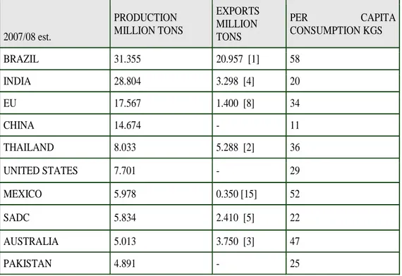
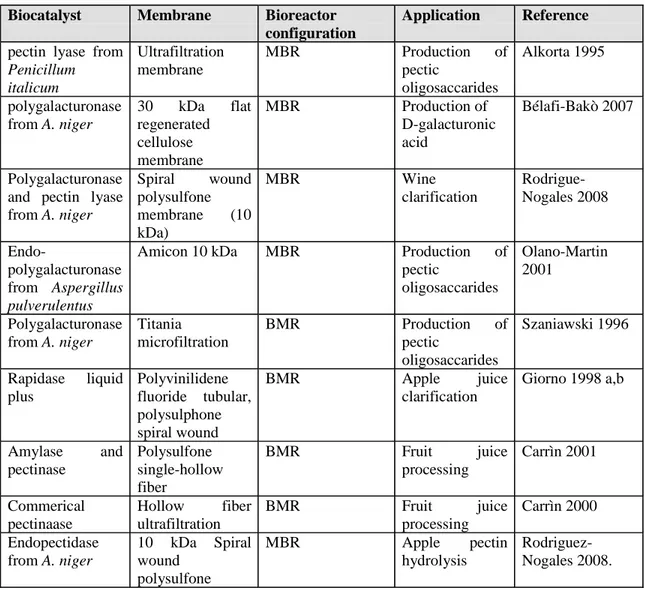
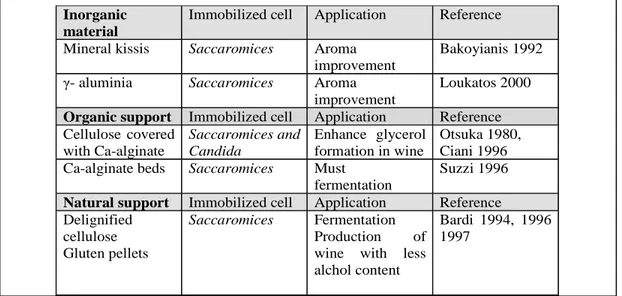
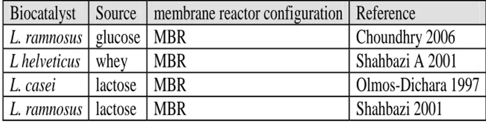
a
Università della Calabria
Facoltà di Ingegneria
Scuola di Dottorato “Pitagora” in Scienze Ingegneristiche
XXIII - I Ciclo (2007-2010)
SETTORE SCIENTIFICO DISCIPLINARE: CHIM/07 – Fondamenti Chimici delle Tecnologie
A Dissertation submitted in partial fulfilment of the requirements for the
Doctorate of Philosophy degree on
DEVELOPMENT OF SUBMERGED BIOCATALYTIC
MEMBRANE REACTORS FOR INNOVATIVE PRODUCTION
SYSTEMS
Supervisor Student
--- ---
Prof. Enrico DRIOLI Sudip CHAKRABORTY
Co-Supervisor Coordinator of PhD
--- ---
Dr. Lidietta GIORNO
Prof. Sergio RIZZUTI
e
Summary
Enzymatic membrane bioreactors (MBR) have been studied for very different applications since many years. Submerged MBR has also been successfully used for treatment of waste water. In the existing submerged configuration, the membrane works as the separation unit operation while the bioconversion is carried out by microorganisms suspended in the tank reactor. In the present work, a novel approach that combines the concept of biocatalytic membranes and submerged modules is proposed. Lipase enzyme from Candida rugosa has been immobilized in polyethersulphone hollow fibre (PES HF) membrane in order to develop a two separate phase biocatalytic submerged membrane reactor in which the membrane works as both catalytic and separation unit. The performance of the biphasic submerged enzymatic membrane reactor was evaluated based on the fatty acids extraction in the aqueous phase. The catalytic activity of lipase immobilized in the submerged system was studied at various operating conditions such as pH, T and fluid dynamics parameters. Furthermore, the submerged biocatalytic membrane reactor is intended for production of valuable components from waste streams, such as fried cooked oils. In this work, the proof of principle in using the submerged biocatalytic membrane reactor for the production of fatty acids from cooked vegetable oil (olive, corn, sunflower and soya oil ) has been performed.
The overall thesis is organized in four different chapters. In the Chapter 1 the principles of membranes and membrane bioreactors are reported. The analysis of state of the art of membrane bioreactor and their application with particular emphasis in the
f
food application has been illustrated in Chapter 2. Chapter 3 describes the materials and methods used in the present work and the results are discussed in Chapter 4.
h
This thesis is dedicated to
Tombaba, Munu Ma, my brother Goi, Misty, my family, Lidia & Prof. Drioli
Without all of your support, encouragement and inspiration it would never have been accomplished
II
Contents
Summary………...
e
Acknowledgement………IV
Chapter 1: Introduction to membranes and membrane bioreactors
1.1 Membrane and its function………... 02
1,2 Different Membrane Processes 04 1.3 The membrane transport mechanisms 06 1.4 Materials and structures of synthetic membranes 08
1.4.1Symmetric and asymmetric membranes 09
1.4.2. Porous membranes 11 1.4.3. Homogeneous dense membranes 13
1.5 System configuration 14
1.6. Enzyme 16
1.7 Different Immobilization Technique 19
1.7.1. Entrapment 19
1.7.2. Gelification 20
1.8 Binding to the membrane 20
1.8.1. Physical adsorption 21
1.8.2. Ionic Binding 21
1.8.3. Covalent Binding 22
1.8.4. Cross-linking 23
1.9 Site specific immobilization method 24
1.10 Membrane Reactor 26
1.10.1 Membrane bioreactors 27
1.10.2 Biocatalytic membrane reactors 29
1.11 Principles of biocatalytic membrane reactor 30
1.12 Enzyme immobilized on the surface 33
1.13 Enzyme immobilized into the porous matrix of membranes 35
Chapter 2: Membrane bioreactors research,development and Applications
2.1 Chronological distribution of MBR research 412.2 Areas of MBR application 44
2.3 Applications of biocatalysts in MBR 45
2.3.1 Membrane bioreactor in Sugar and Starch processing 46
2.3.2 Membrane bioreactor in Oil & Fat processing industry 50
III
2.3.3Membrane Bioreactors in Hard drink
industry and liquid beverages 54
2.3.4. Beer 60
2.3.5 Ethanol production 61
2.4 Membrane bioreactor application in liquid beverages 62
2.4.1 Fruit juices production 62
2.5 Functional food production in milk and whey field
by membrane bioreactor 65
2.5.1 Lactose hydrolysis 66
2.5.2 Protein hydrolysis in milk and whey
by MBR 68
2.6 The production of pharmaceuticals using
biocatalytic membrane reactors 71 2.7 Recent Development of Biocatalytic Membrane
Reactor (BMR) 73
References 76
Chapter 3: Material and Methods
3.1 Chemicals 84
3.2 Reaction equation and bi-phase system 85
3.3 Equipments and operation mode 87
3.3.1. Preparation of Modules 87
3.4 Membrane Characterization 89
3.5 Enzyme immobilization 90
3.6 Immobilization Set Up and Procedure 92
3.6.1 Enzyme immobilization in side stream module 92 3.6.2 Enzyme immobilization in submerged module 94 3.7 Reaction Procedure in Bi-phase system in
Side stream Module 95 3.8 Reaction Procedure in Bi-phase system in
Submerged configuration 96
3.9 Reaction rate measurement 97
IV
Chapter 4: Results and Discussions
4.1 Membrane Characterization 103
4.2 Immobilization 106
4.3 Reaction in Bi-phase system 109
4.4 Optimization of Submerged Biocatalytic Membrane
Reactor 112
4.4.1 Influence of pH 112
4.4.2 Influence of Temperature 116
4.4.3 Influence of Organic Phase Stirring 118 4.4.4. Influence of axial velocity of the aqueous phase 120
4.4.5 Influence of TMP 122
4.5 Test of the system with fried oil 124
References 127
Conclusions 129
V
ACKNOWLEDGEMENTS
First of all, I would like to thank the Research Institute on Membrane Technology, nowadays called ITM-CNR and University of Calabria, for the opportunity of making the research that is the core of this thesis.
I am grateful to my Supervisor Prof. Enrico Drioli and my co-supervisor Dr. ssa. Lidietta Giorno for continuously inspiring me to approach new problems, overcome challenges and for allowing me the freedom to pursue the independent research on development of submerged membrane bioreactor. Words are very poor to express my gratefulness. Your presence consists of an example to me. It was your’s unwavering support and faith in my work that helped me to successfully complete my research and made this challenging journey a smooth and memorable one. Prof. Drioli and Lidietta have served as a true mentor – as much in my academic activities, as in the non-academic ones.
A special thanks to Lidietta for her support during my time here in this paradise “ My Lab”. I am so grateful to her for her advices, understanding and behaviors to me like a mother during the difficult and sometime unfortunate days of my life here in Italy. She made me complete this thesis.
I extend sincere thanks to Prof. S.Rizzuti, Prof. CB, Prof. S. Basu for their suggestions and valuable advice before and during my doctoral work . My sincere thanks to
VI
professors from Dept of Materials and Chemical Engineering at University of Calabria for their support during my research work.
I especially want to thank the current and former lab members like Raff, Monica, Alex, Paola, Fabio, Rita, Giovanni, Samuel and many others for their company and helping hands all the time.
Thanks to Pino, Alessandra, Alberto, Alfredo, Gianpiero, Laura, Loredana, Mariella, John, Franco, Gabriel, Adolfo, Teresa, Catia, Annamaria, Francesca (probably I forgot a couple). It has always been a pleasure talking with you at ITM and extending your helping hand towards me in every situation. Thank you all for your support.
At ITM/UNICAL I was fortunate to meet many people from different cultural background and from different parts of the world. Thanks to all of you.
My deep and sincere thanks go to the people that always supported me all these years: Many thanks go to all my friends in India, Germany, Greece, The Netherlands, Hungary, Denmark, Norway , US and off course Cosenza for reminding me there is life out of work.
Grazie mille a miei carissimi colleghi in dottorato Emma, Rosalinda & many many more per aiutarmi sembre sul e fuori dil lavoro. Siete grandi.
Thank you George for your valuable time , support , encouragement since last 3 years during PhD and still going on.
VII
Bohut Dhanyabad my Indian friends here in UNICAL because you are sincerely, always here for me.
Bagio, Τάσο, Θανάση, σας ευχαριστώ για αυτό που είστε. Τι.. να πω κι άλλα!;;
Finally I would like to thank those without whom I would never be able to accomplish anything.Tombaba, Ma, Gobin, Misty, you’ve been through many sacrifices and you’ve sustained many things in order to support me continuously all these years. Words cannot express your contribution neither I can describe your patience and dedication. Thank you very much for standing by me all this time.
For anyone maybe not mentioned, it was not intended. My thanks go to everyone I met last three years.
I am grateful to International Doctoral School “Pitagora” for financial support during these three years.
Introduction to membranes and membrane bioreactors
2
Chapter
1
Introduction to membranes and membrane bioreactors
3
In this chapter the basic principles that govern membrane bioreactors and in particular biocatalytic membrane reactors are reported. First, the discussion will focus on the membrane, its characteristic, morphological structure, etc. Then, methods for enzyme immobilization in membranes and general aspects of biocatalytic membrane reactors kinetics will be discussed.
1.1 Membrane and its function
A precise and complete definition of a membrane that covers all its aspects is rather difficult, even when the discussion is limited to synthetic structures as in this outline. Various definitions have been reported in the literature, most of them focusing on the selective properties of the membrane. For example, Lonsdale defined a synthetic membrane as an interphase that separates two phases and restricts the transport of various components in a specific manner [Lonsdale 1982]. In new membrane processes, such as membrane contactors, the membrane is a non-selective barrier that separates and contacts the two adjacent phases. Therefore, in the most general sense we can define a membrane as a selective or non-selective barrier that separates and/or contacts two adjacent phases and allows or promotes the exchange of matter, energy, and information between the phases in a specific or non-specific manner. Separation of a mixture in a membrane process is the result of different transport rates of different components through the membrane. The transport rate of a component through a membrane is determined by driving forces such as concentration, pressure, temperature, and electrical potential gradients, and the concentration and mobility of the component in the membrane matrix.
4
A membrane can be homogeneous or heterogeneous, symmetric or asymmetric in structure. It may be solid or liquid and may consist of organic or inorganic materials. It may be neutral or it may carry positive or negative charges, or functional groups with specific binding or complexing abilities. Its thickness can be less than 100 nm to more than a millimeter. The electrical resistance may vary from more than 1,000,000 ohm cm2 to less than one ohm cm2. The term "membrane", therefore, includes a great variety of materials and structures, and a membrane can often be better described by its function rather than by its structure. Some materials, such as protective coatings, or packaging materials, show typical membrane properties, and are in fact membranes. Most materials functioning as membranes have one characteristic property in common: they restrict the passage of different components in a very specific manner. In some cases, a hydrophobic polymeric membrane may allow the passage of water as vapor phase but not as liquid phase, as for example in membrane distillation. In other cases, e.g. membrane contactors, the porous structure of the membrane material functions as a barrier that keeps in contact two adjacent phases between which a mass transfer occurs, and separates them at the same time. In both cases the membrane has no direct effect on the transport of various components and is non-selective. The concept of a selective and non-selective membrane is illustrated in Fig 1.1 which shows in a) a membrane which is highly selective and capable of separating, e.g. two enantiomers and b) a membrane that acts as a barrier between two phases and avoids the mixing of the phases but has no effect on the transport of different components from one phase to the other.
Introduction to membranes and membrane bioreactors
5
Fig. 1.1. a) Membrane which is selective for the transport of different components such as two enantiomers and
b) Membrane which separates a liquid and a vapour phase and allows passage of vapour molecules but is not selective for the transport of different components.
1.2 Different membrane processes
Membrane processes can be grouped according to the applied driving forces into: (1) hydrostatic pressure driven processes such as reverse osmosis, nano-, ultra- and microfiltration or gas separation, pervaporation;
(2) concentration gradient or chemical potential driven processes such as dialysis, Donnan dialysis, pervaporation, and membrane contactors, such as membrane based solvent extraction, membrane scrubbers and strippers, osmotic distillation; (3) electrical potential driven processes such as electrodialysis; and
(4) temperature difference driven membrane processes such as membrane distillation. The molecular mixture which will be separated is referred to as feed, the mixture
containing the components retained by the membrane is called the retentate and the mixture composed of the components that have permeated the membrane is referred to as permeate (or filtrate in micro- and ultrafiltration). Table 1.1. lists the basic properties of membrane operations.
d rivin g fo rce ∆C , ∆p , ∆T m e m b ra n e w ith sp e cific se le ctivity R1 R2 R3 R1 R2 R3 R1 R2 R3 d rivin g fo rce ∆C , ∆p , ∆T va p o u r p h a se liq u id p h a se m e m b ra n e w ith n o sp e cific co m p o n e n t se le ctivity a) b)
6
Table 1.1. Basic concepts of different membrane operations
Process Concept Driving
Force Mode of transport Species Passed Species Retained Microfiltrati on (MF) Feed Retentate Solvent Microporous membranes pressure difference 100 - 500 kPa size exclusion convection solvent (water) and dissolved solutes suspended solids, fine particulars , some colloids Ultrafitlratio n (UF) Feed Retentate Solvent UF membranes pressure difference 100 - 800 kPa size exclusion convection solvent (water) and Low molecular weight solutes (<1000 Da) macrosolu tes and colloid s Nanofiltratio n (NF) Feed Retentate Solvent NF membranes pressure difference 0.3 - 3 MPa size exclusion solution diffusion Donnan exclusion solvent (water), low molecular, weight solutes, monovalent ions molecular weight compound s > 200 Da multivalen t ions Reverse Osmosis (RO) pressure difference 1 - 10 MPa solution diffution mechanism solvent (water) dissolved and suspended solids Gas Separation (GS) Feed Retentate Sweep Dense/Porous membrane Permeate pressure Difference 0.1 – 10 MPa solution diffusion mechanism gas molecules having Low molecular weight or high solubility-diffusivity gas molecules having high molecular weight or low solubility-diffusivity Pervaporatio n (PV) chemical potential or concentratio n difference solution diffusion mechanism high permeable solute or solvents less permeable solute or solvents Electrodialy sis (ED) electrical potential difference 1 – 2 V / cell pair Donnan exclusion solutes (ions) Small quantity of solvent non-ionic and macromol ecular species Feed Retentate Solvent NF membranesRO membranes Feed Retentate Solvent NF membranesDense membrane
Liquid Vapour Permeate Concentrate Product Feed + -+ + + +
-Ion exchange membrane
-Concentrate Product Feed + -+ + + +
-Ion exchange membrane
-Introduction to membranes and membrane bioreactors 7 Dialysis (D) concentratio n difference
diffusion solute (ions
and low MW organics) Small solvent quantity dissolved and suspended solids with MW > 1000 Da Membrane contactors (MC) chemical potential, concentratio n difference; temperature difference diffusion compounds soluble in the extraction solvent; volatiles compound s non soluble in the extraction solvent; Non volatiles Membrane based solvent extraction (MBSX) chemical potential or Concentratio n difference diffusion partition compounds soluble in the extraction solvent compound s non soluble in the extraction solvent Membrane Distillation (MD) temperature difference
diffusion volatiles non
volatiles Supported liquid membranes (SLM) concentratio n difference diffusion ions, low MW organics ions, less permeable organics Membrane reactors (MR)
various various permeable
product
non permeable reagents
1.3The membrane transport mechanisms
The mechanism by which certain components are transported through a membrane can also be very different. In some membranes, for example, the transport is based on viscous flow of a mixture through individual pores in the membrane caused by a hydrostatic pressure difference between the two phases separated by the membrane. This type of transport is referred to as viscous flow. The components that permeate through the membrane are transported by
convective flow through micropores under a gradient pressure as driving force and the
Feed Retentate Solvent NF membranesDialysis membrane
Dialysate feed Impurities Purified stream Feed Retentate Sweep Dense/Porous membrane Permeate Porous membrane Feed Retentate Sweep Dense/Porous membrane Permeate Porous membrane Feed Retentate Solvent NF membranesPorous membrane
Cool stream Cool Distillate
Warm concentrate Warm feed Liquid
Liquid
vapour
Feed
Product A
Supported liquid membrane Product B Feed
Product A
Supported liquid membrane Product B
Feed Retentate Solvent NF membranesReactive membrane
Product Product
8
separation occurs because of size exclusion as indicated in Fig 1.2 a). Darcy’s Law describes this type of transport. It is the dominant form of mass transport in micro- and ultrafiltration but also occurs in other membrane processes.
If the transport through a membrane is based on the solution and diffusion of individual molecules in the non-porous membrane matrix due to a concentration or chemical potential gradient the transport is referred to as diffusion. The separation occurs because of different solubility and diffusivity of components into the membrane material as indicated in Figure 1.2 b). The Fick’s Law describes this type of transport. The diffusion of molecules through homogeneous dense membranes occurs through the free volume elements, or empty spaces between polymer chains caused by thermal motion of the polymer molecules, which fluctuate in position and volume on the same time scale as the molecule permeates. The transition between fluctuating free volumes and individual permanent pores is controversial. In general it is considered in the range of 5-10 Å in diameter.
This form of mass transport is dominant in reverse osmosis, gas separation, pervaporation or dialysis but it may occur in other processes too. If an electrical potential gradient across the membrane is applied to achieve the desired transport of certain components through the membrane the transport is referred to as migration. Migration occurs in electrodialysis and related processes and is limited to the transport of components carrying electrical charges such as ions.
Introduction to membranes and membrane bioreactors
9
Fig. 1.2. a) The sieving mechanism of a porous membrane and
b) The solution diffusion mechanism in a non-porous membrane.
1.4 Materials and structures of synthetic membranes
Synthetic membranes show a large variety in their physical structure and the materials they are made from. Based on their structure they can be classified in four groups:
• porous membranes,
• homogeneous solid membranes,
• solid membranes carrying electrical charges,
• liquid or solid films containing selective carriers.
Furthermore, the structure of membranes may be symmetric, i.e. the structure is identical over the entire cross-section of the membrane or it may be asymmetric, i.e. the structure varies over the cross-section of the membrane.
The materials used for the preparation of membranes can be polymers, ceramics, glass, metals or liquids. The materials may be neutral or carry electrical charges, i.e. fixed ions. The membrane conformation can be flat, tubular or a hollow fiber. The schematic drawing of Fig. 1.3 illustrates the morphology, materials and configuration of some technically relevant synthetic membranes.
10
Fig. 1.3 Schematic drawing illustrating the various materials, structures and configuration of technically relevant synthetic membranes.
1.4.1 Symmetric and asymmetric membranes
As indicated earlier synthetic membranes may have a symmetric or an asymmetric structure. In a symmetric membrane the structure and the transport properties are identical over the entire cross-section and the thickness of the entire membrane determines the flux. Symmetric membranes are used today mainly in dialysis and electrodialysis. In asymmetric membranes structural as well as transport properties vary over the membrane cross-section. An asymmetric membrane consists of a 0.1 to 1 µm thick "skin" layer on a highly porous 100 to 200 µm thick substructure. The skin represents the actual selective barrier of the asymmetric membrane. Its separation characteristics are determined by the nature of the material or the size of pores in the skin-layer. The mass flux is determined mainly by the "skin" thickness. The porous
membrane materials
membrane structures
polymers ceramics glass metals liquids
homogeneous films
cylindrica pores
porous skin
layer homogeneous skin layer
sponge-type structures
symmetric asymmetric
integral asymmetric composite structures
homogeneous skin layer
Membrane configuration
Introduction to membranes and membrane bioreactors
11
sub-layer serves only as a support for the mostly thin and fragile skin and has little effect on the separation characteristics or the mass transfer rate of the membrane Fig.
1.4. Asymmetric membranes are used primarily in pressure driven membrane
processes such as reverse osmosis, ultrafiltration, or gas and vapor separation, since here the unique properties of asymmetric membranes, i.e. high fluxes and good mechanical stability can best be utilized. Two techniques are used to prepare asymmetric membranes: one utilizes the phase inversion process which leads to an integral structure with the skin and the support structure made from the same material in a single process [Kesting, 1971], and the other resembles a composite structure where a thin barrier layer is deposited on a porous substructure in a two step process [Cadotte et al., 1981]. In this case barrier and support structures are generally made from different materials.
Fig 1.4
1.4.2 Porous membranes
A porous structure represents a very simple form of a membrane, which closely resembles the conventional fiber filter as far as the mode of separation is concerned. These membranes consist of a solid matrix with defined holes or pores which have diameters ranging from less than 1 nm to more than 10 µm. The macromolecular size of the species to be separated plays an important role in determining the pore size of the membrane to be utilized and the related membrane process. Porous membranes with average pore
those with average pore diameters in the intermediate range between 2 and 50 nm are 12
.4 : Schematic diagrams of the principal types of membranes
Porous membranes
A porous structure represents a very simple form of a membrane, which closely resembles the conventional fiber filter as far as the mode of separation is concerned. These membranes consist of a solid matrix with defined holes or pores which have ranging from less than 1 nm to more than 10 µm. The macromolecular size of the species to be separated plays an important role in determining the pore size of the membrane to be utilized and the related membrane process. Porous membranes with average pore diameters larger than 50 nm are classified as macroporous, and those with average pore diameters in the intermediate range between 2 and 50 nm are
al types of membranes
A porous structure represents a very simple form of a membrane, which closely resembles the conventional fiber filter as far as the mode of separation is concerned. These membranes consist of a solid matrix with defined holes or pores which have ranging from less than 1 nm to more than 10 µm. The macromolecular size of the species to be separated plays an important role in determining the pore size of the membrane to be utilized and the related membrane process. Porous membranes diameters larger than 50 nm are classified as macroporous, and those with average pore diameters in the intermediate range between 2 and 50 nm are
Introduction to membranes and membrane bioreactors
13
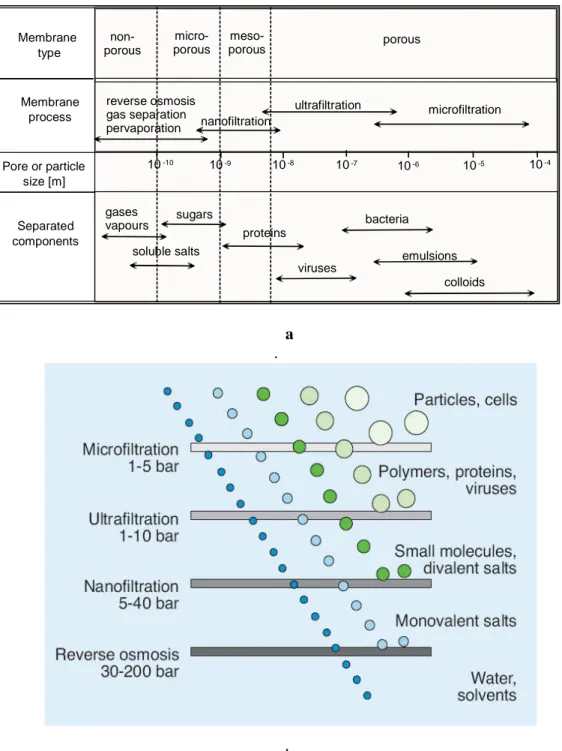
classified as mesoporous. Membranes with average pore diameters between 0.1 and 2 nm are classified as microporous. Dense membranes have no individual permanent pores, but the separation occurs through fluctuating free volumes. The schematic representation of such classification is illustrated in Fig. 1.5 (a,b).
a .
b
Fig. 1.5 a.b.. Schematic classification of membranes, related processes and separated components
10-10 Membrane type Membrane process Pore or particle size [m] Separated components 10-9 10-8 10-7 10-6 10-5 10-4 non-porous micro-porous meso-porous porous reverse osmosis gas separation pervaporation nanofiltration ultrafiltration microfiltration gases vapours soluble salts sugars proteins viruses bacteria emulsions colloids
14
In pressure driven membrane processes the separation of the various components is achieved by a sieving mechanism with the pore diameters and the particle sizes being the determining parameters. In thermally driven membrane processes the separation is based on the principle of phase equilibrium and the non-wet ability of membrane pores is the determining parameter. Porous membranes can be made from various materials such as ceramics, graphite, metal or metal oxides, and various polymers. Their structure may be symmetric, i.e. the pore diameters do not vary over the membrane cross-section, or they can be asymmetric, i.e. the pore diameters increase from one side of the membrane to the other typically by a factor of 10 to 1000. The techniques for the preparation of porous membranes can be rather different and include simple pressing and sintering of polymer or ceramic powders, irradiation and leaching of templates as well as phase inversion and polymer precipitation procedures or sol-gel conversion techniques. Porous membranes are used to separate components that differ markedly in size or molecular weight in processes such as micro- and ultrafiltration or dialysis [Cheryan, 1998].
1.4.3 Homogeneous dense membranes
A homogeneous membrane is merely a dense film through which a mixture of molecules is transported by a pressure, a concentration, or an electrical potential gradient. The separation of the various components of a mixture is directly related to their transport rates within the membrane phase, which is determined by their diffusivities and concentrations in the membrane matrix. Therefore, homogeneous membranes are referred to as solution-diffusion type membranes [Merten, 1966]. They
can be prepared from polymers, metals, metal alloys or, in some cases, ceramics which may also carry positive or negative electrical charges. Since the mass transport in homogeneous membranes is based on diffusion their permeabilities are rather low. Homogeneous membranes are used mainly to separate components which are similar in size but have different chemical nature in processes such as reverse osmosis, gas and vapor separation, and pervaporation [
asymmetric membrane
supported by a porous substructure. Some of the well known polymer used to prepare different membranes has been tabled in table
Table 1.2 : Polymeric membrane materials (Judd, 2006; Mulder, 1996)
1.5 System configuration
The membrane step can be implemented into an MBR system in two ways: sidestream or immersed. In sidestream configuration the membranes are placed externally from the bioreactor, schematically presented in
generation MBRs were designed a
was traditionally prevented by applying a high liquid cross flow through the membrane tubes.
Introduction to membranes and membrane bioreacto
15
e prepared from polymers, metals, metal alloys or, in some cases, ceramics which may also carry positive or negative electrical charges. Since the mass transport in homogeneous membranes is based on diffusion their permeabilities are rather low. s membranes are used mainly to separate components which are similar in size but have different chemical nature in processes such as reverse osmosis, gas and vapor separation, and pervaporation [Raymond et al., 1992
asymmetric membrane structures are used which consist of a thin homogeneous skin supported by a porous substructure. Some of the well known polymer used to prepare different membranes has been tabled in table 1.2.
Polymeric membrane materials (Judd, 2006; Mulder, 1996)
System configuration
The membrane step can be implemented into an MBR system in two ways: sidestream or immersed. In sidestream configuration the membranes are placed externally from the bioreactor, schematically presented in
generation MBRs were designed according to the sidestream configuration. Fouling was traditionally prevented by applying a high liquid cross flow through the membrane tubes.
Introduction to membranes and membrane bioreactors
e prepared from polymers, metals, metal alloys or, in some cases, ceramics which may also carry positive or negative electrical charges. Since the mass transport in homogeneous membranes is based on diffusion their permeabilities are rather low. s membranes are used mainly to separate components which are similar in size but have different chemical nature in processes such as reverse osmosis, gas Raymond et al., 1992]. In these processes structures are used which consist of a thin homogeneous skin supported by a porous substructure. Some of the well known polymer used to prepare
Polymeric membrane materials (Judd, 2006; Mulder, 1996)
The membrane step can be implemented into an MBR system in two ways: sidestream or immersed. In sidestream configuration the membranes are placed externally from the bioreactor, schematically presented in Fig. 1.6. The first ccording to the sidestream configuration. Fouling was traditionally prevented by applying a high liquid cross flow through the
16
Fig 1.6: Side stream configuration
Applying a high cross flow velocity makes the membranes less sensitive to fouling and thus allows for employing a relatively high TMP or flux. The main disadvantage of the traditional sidestream configuration is the high energy consumption required for the cross flow. In the immersed or internal configuration the membrane modules are submerged directly into the activated sludge, either in a separate membrane tank or directly in the bioreactor. The immersed MBR configuration is schematically presented in Fig. 1.7. Nowadays the membranes are more commonly placed in a separate membrane tank; in the first place this allows better control over the filtration process and besides this the wastewater undergoes superior biological treatment before reaching the membrane. The disadvantage of a separate membrane tank is the higher energy consumption for recirculation and aeration.
Within immersed MBR systems two different membrane configurations are applied: hollow fibre and flat sheet
sidestream and the immersed MBR configuration are summarized in 2006; Judd 2006).
Table 1.3: Summary of sidestream and immersed MBR characteristics
1.6. Enzyme
Different enzymes have been already applied in many different biocatalytic applications. It is well understood that the enzyme has some specific advantages over inorganic, metal-derived or chemical catalysts. The interest in lipase oriented research is increasing over the past decades. This is primarily due to their ability to utilize a wide spectrum of substrates, high stability towards extremes of temperature, pH and organic solvents, and chemo
and high added value can be obtained. Moreover, the use of enzyme decreases the side reactions and simplifies post
Activation energy of this enzyme is low, thus, require mild reaction conditions of pH and temperature, which lead to decrease in energy consumption and less thermal damage to reactants and products (Balcao et al., 1996). Lipases (EC.3.1.1.3, triacylglycerol acylhydrolyse) have been used for many years. Therefore, customization of lipases by chem
Introduction to membranes and membrane bioreacto
17
Within immersed MBR systems two different membrane configurations are applied: hollow fibre and flat sheet membranes. Some specific characteristics of the traditional sidestream and the immersed MBR configuration are summarized in
Summary of sidestream and immersed MBR characteristics
Different enzymes have been already applied in many different biocatalytic applications. It is well understood that the enzyme has some specific advantages over derived or chemical catalysts. The interest in lipase oriented research reasing over the past decades. This is primarily due to their ability to utilize a wide spectrum of substrates, high stability towards extremes of temperature, pH and organic solvents, and chemo-, regio- and enantioselectivity. Products with high purity d high added value can be obtained. Moreover, the use of enzyme decreases the side reactions and simplifies post-reaction separation problems (Pandey et al., 1999). Activation energy of this enzyme is low, thus, require mild reaction conditions of pH emperature, which lead to decrease in energy consumption and less thermal damage to reactants and products (Balcao et al., 1996). Lipases (EC.3.1.1.3, triacylglycerol acylhydrolyse) have been used for many years. Therefore, customization of lipases by chemical and physical modifications has been attempted to Introduction to membranes and membrane bioreactors
Within immersed MBR systems two different membrane configurations are applied: membranes. Some specific characteristics of the traditional sidestream and the immersed MBR configuration are summarized in Table 1.3 (Evenblij
Summary of sidestream and immersed MBR characteristics
Different enzymes have been already applied in many different biocatalytic applications. It is well understood that the enzyme has some specific advantages over derived or chemical catalysts. The interest in lipase oriented research reasing over the past decades. This is primarily due to their ability to utilize a wide spectrum of substrates, high stability towards extremes of temperature, pH and and enantioselectivity. Products with high purity d high added value can be obtained. Moreover, the use of enzyme decreases the side reaction separation problems (Pandey et al., 1999). Activation energy of this enzyme is low, thus, require mild reaction conditions of pH emperature, which lead to decrease in energy consumption and less thermal damage to reactants and products (Balcao et al., 1996). Lipases (EC.3.1.1.3, triacylglycerol acylhydrolyse) have been used for many years. Therefore, ical and physical modifications has been attempted to
18
improve their catalytic properties in hydrolysis and synthesis involving aqueous, non-aqueous and organic solvents. In addition, the cost of enzyme can be reduced by the application of molecular biological tools, this may allow the production of lipases in large quantities and with genetically enhanced properties (Villeneuve et al., 2000). These properties allow them to catalyze reactions with reduced side products, lowered waste treatment costs and under conditions of mild temperature and pressure. Secondly, they are widely distributed among the animals, plants and microorganisms and their activity is greatest against water-insoluble substrates and enhanced at the substrate (oil)-water interface; that is, they exhibit .interfacial activation. Thus, maximum activities are obtained in emulsion systems where high surface areas of the substrate can be obtained. Lipases are active not only in normal phase emulsions where the substrate is emulsified into an aqueous system (oil-in-water), but they are also active, often more active, in invert (water-in-oil) emulsions and in reverse micelle systems containing an organic solvent solution of the substrate. Thus, it is not surprising that lipases, for many years, served as models for studying the regulation of interfacial, enzyme-catalyzed reactions. Final and the most important reason is linked to the enzyme’s medical relevance, particularly to atherosclerosis and hyperlipidemia, and its importance in regulation and metabolism, since products of lipolysis such as free fatty acids and diacylglycerols play many critical roles, especially as mediators in cell activation and signal transduction. Important areas of industrial applications of microbial lipases has summarized in Table 1.4:
Table 1.4 : Industrial applications of microbial lipases
(http://www.iisc.ernet.in/~currsci/july10/articles18.htm
Introduction to membranes and membrane bioreacto
19
Industrial applications of microbial lipases
http://www.iisc.ernet.in/~currsci/july10/articles18.htm).
20
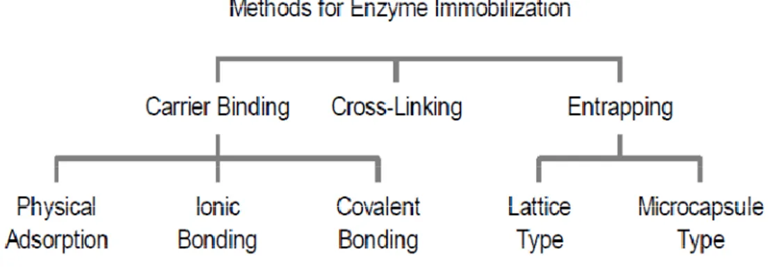
1.7 Different Immobilization Technique
The catalyst/enzyme can be entrapped within the membrane, gelified on the membrane or bounded to the membrane (Strathmann, 2006). A scheme of immobilization techniques is reported in Fig. 1.8 and detail discussion later on.
Fig 1.8 : Classification of enzyme immobilization techniques
1.7.1. Entrapment
The entrapment method (Fig: 1.9 ) of immobilization is based on the localization of an enzyme within the membrane. It is done in such a way as to retain protein while allowing penetration of substrate. Asymmetric hollow fibre can provide an interesting support for enzyme immobilization. The enzyme can be entrapped in the sponge layer by cross-flow filtration in the case in which the pore size in the dense layer must retain the enzyme, permitting the passage of the substrate. The amount of biocatalyst loaded, its distribution and activity through the support and its lifetime are very important parameters to properly orientate the development of such systems. The amount of immobilized protein can be determined by the mass balance between initial and final solutions (Giorno, 1995). The transport of the substrate through the
enzyme-Introduction to membranes and membrane bioreactors
21
loaded membrane is another important parameter as well as the residence-time (Strathmann, 2006).
Fig. 1.9. : Schematic illustration of entrapment methods 1.7.2. Gelification
The gelification (Fig 1.10) of the biocatalyst on the membrane is based on one of the main drawbacks of membrane processes: concentration polarization phenomena. Disadvantages of this systems is the reduction of the catalytic efficiency, due to mass transport limitations and the possibility to preferential pathways in the enzyme gel layer (Drioli 1989).
Fig 1.10: Gelification method
1.8 Binding to the membrane
The bound of the biocatalyst to the membrane can be divided in: physical absorption, ionic binding, covalent-linking and cross-linking.
G e lif ic a t io n
G e lif ic a t io n
22 1.8.1. Physical adsorption
Physical adsorption (Fig. 1.11) of an enzyme onto a solid is probably the simplest way of preparing immobilized enzymes. The method relies on non-specific physical interaction between the enzyme protein and the surface of the matrix.
A major advantage of adsorption as a general method of insolubilizing enzymes is that usually no reagents and only a minimum of activation steps are required. As a result, adsorption is cheap, easily carried out, and tends to be less disruptive to the enzymatic protein than chemical means of attachment, the binding being mainly by hydrogen bonds, multiple salt linkages, and Van der Waal's forces. In this respect, the method bears the greatest similarity to the situation found in biological membranes in vivo and has been used to model such systems.
Because of the weak bonds involved, desorption of the protein resulting from changes in temperature, pH, ionic strength or even the more presence of substrate, is often observed. Another disadvantage is non-specific further adsorption of other proteins or other substances (Goel, 1994).
Fig 1.11: Physical Adsorption method
1.8.2. Ionic Binding
The ionic binding method (Fig 1.12) relies on the ionic binding of the enzyme protein to water-insoluble carriers containing ion-exchange residues. Polysaccharides and synthetic polymers having ion-exchange centers are usually used for carriers. The binding of enzyme to the carrier is easily carried out, and the conditions are much
Introduction to membranes and membrane bioreactors
23
milder than those needed for the covalent binding method. Hence, the ionic binding method causes little changes in the conformation and the active site of the enzyme, and so yields immobilized enzymes with high activity in most cases. As the binding forces between enzyme protein and carriers are less strong than in covalent binding; leakage of enzyme from the carrier may occur in substrate solutions of high ionic strength or upon variation of pH. The main difference between ionic binding and physical adsorption is that the enzyme to carrier linkages is much stronger for ionic binding although less strong than in covalent binding.
Fig 1.12 : The ionic binding method
1.8.3. Covalent Binding
The covalent binding method (Fig: 1.13) is based on the binding of enzymes and membrane by covalent bonds. The functional groups that take part in this binding of enzyme to membrane can be amino, carboxyl, sulfhydryl, hydroxyl, imidazole or phenolic groups which are not essential for the catalytic activity. In order to protect the active site, immobilization can be carried out in the presence of its substrate or a competitive inhibitor. Activity of the covalent bonded enzyme depends on the size and shape of carrier material, nature of the coupling method, composition of the carrier material and specific conditions during coupling. The main advantage of the covalent attachment is that such an immobilization is very stable. Unlike physical adsorption, the binding force between enzyme and carrier is so strong that no leakage of the
24
enzymes occurs, even in the presence of substrate or solution of high ionic strength. Moreover, the obtained immobilized enzymes are usually very stable and resistant to extreme conditions (pH range, temperature). Finally, a large number of different supports and methods to activate them are available. However, experimental procedures are obviously more difficult to carry out than for physical adsorption. The 3-D structure of the protein is considerably modified after the attachment to the support. This modification may lead to a loss of the initial activity of the biocatalyst (Villeneuve et al., 2000). Examples of derivatized lipases obtained through this procedure include PEG modified lipase, fatty acid-modified lipase, amidinated lipase, and detergent-modified lipase (Villeneuve et al., 2000). (Xie, 1999) (Charcosset 2006).
Fig 1.13: Covalent binding method
1.8.4. Cross-linking
Immobilization of enzymes can be also achieved by intermolecular cross-linking of the protein, either to other protein molecules or to functional groups on an insoluble support matrix. Cross-linking (Fig 1.14) an enzyme to itself is both expensive and insufficient, as some of the protein material will inevitably be acting mainly as a support, resulting in relatively low enzymatic activity. Generally, cross-linking is best used in conjunction with one of the other methods.Since the enzyme is covalently linked to the support matrix, very little desorption is likely using this method.
Introduction to membranes and membrane bioreactors
25
Fig 1.14 : Cross-linking of enzyme
1.9 Site specific immobilization method
While immobilization of small molecule is typically easier, the active centre of larger proteins may no longer be accessible after immobilization. In these cases, improvement can be achieved by introducing a spacer molecule (Nouaimi 2001). Good steric accessibility of active sites can be obtained by oriented immobilization of glycoprotein enzymes through their carbohydrate moieties (Turkova 1999, Křenková 2004). Different approaches are developed in order to accommodate site-specific immobilization of enzymes with different structural characteristics, as gene fusion to incorporate a peptidic affinity tag at the N- or C- terminus of the enzyme; post translational modification to incorporate a single biotin moiety on enzymes; and site-directed mutagenesis to introduce unique cysteins to enzymes (Butterfield et al, 2001).
A small number of reactions have been designed to couple with functional groups on the protein other than the amino and phenolic residues. Aminoethyl cellulose has been coupled to the carboxylic acid residues of enzymatic protein in the presence of carbodiimide, and thiol residues of a protein have been oxidatively coupled to the thiol groups of a cross-linked copolymer of acrylamide and N-acryloyl-cystein.
26
It is possible in some cases to increase the number of reactive residues of an enzyme in order to increase the yield of insolubilized enzyme and to provide alternative reaction sites to those essential for enzymatic activity. As with cross-linking, covalent bonding should provide stable, insolubilized enzyme derivatives that do not leach enzyme into the surrounding solution. The wide variety of binding reactions, and insoluble carriers with functional groups capable of covalent coupling, or being activated to give such groups, makes this a generally applicable method of insolubilization, even if very little is known about the protein structure or active site of the enzyme to be coupled.
In literature there are various routes to carry enzyme immobilization creating a bound on supports, the principal strategies are based on chemical grafting or molecular recognition on porous supports.
The sites involved in this chemistry: carboxylic acid, hydroxyls, amino or quaternary ammonium groups, are created on the surface of porous material by various means like the direct chemical surface treatment or the plasma or UV activation.
The reactive sites thus created allow the attachment of the enzyme by use of coupling reagents such as tosyl chloride, dicyclohexylcarbodiimide, glutaraldehyde etc.
Approaches aiming at creating bio-compatible environments consist in modifying the surface of polymeric membranes by attach of functional groups like sugars, polypeptides and then to absorb the enzymes. Another way considered as of bio-mimetic inspiration and which was shown to be efficient for enzyme attachment, it consists in using the very strong and specific interaction of the small protein avidin for the biotin (Amounas 2000,2002). The tetrameric structure of avidin permits itself to interact with four different molecules of biotin at the same time. Various proteins and
enzyme could be easily biotinylated, and this mode of enzyme grafting has already been used for electrodes production as well
fibres. The different drawbacks of enzyme immobilization is described in the following picture (Fig
Fig 1.15 :
1.10 Membrane Reactor
Membrane reactors are systems where a chemical or biochemical conversion is combined with a membrane separation process.
reactors are identified by the type of catalyst used, traditional chemical catalysts or catalysts of biological origin, which also dictates the operating conditions. Hence, membrane reactors (mainly inorganic) working at high temperature ( 100<T< 600 °C) or membrane bioreactors working at low temperature (< 100 °C) are known. Both types of reactors have two
catalytically inert; it does not participate in the reaction directly; it simply acts as a barrier to reagents allowing selective separation of the product(s) or intermediate(s). This type of system is know
Introduction to membranes and membrane bioreacto
27
enzyme could be easily biotinylated, and this mode of enzyme grafting has already been used for electrodes production as well as for membranes made up of conducting The different drawbacks of enzyme immobilization is described in the following picture (Fig 1.15)
1.15 : Drawbacks of enzyme immobilization techniques
Membrane Reactor
Membrane reactors are systems where a chemical or biochemical conversion is combined with a membrane separation process. The two main areas of membrane reactors are identified by the type of catalyst used, traditional chemical catalysts or logical origin, which also dictates the operating conditions. Hence, membrane reactors (mainly inorganic) working at high temperature ( 100<T< 600 °C) or membrane bioreactors working at low temperature (< 100 °C) are known. Both types of reactors have two main configurations. In one case, the membrane is catalytically inert; it does not participate in the reaction directly; it simply acts as a barrier to reagents allowing selective separation of the product(s) or intermediate(s). This type of system is known with the general term “membrane reactor”. In the other Introduction to membranes and membrane bioreactors
enzyme could be easily biotinylated, and this mode of enzyme grafting has already as for membranes made up of conducting The different drawbacks of enzyme immobilization is described in the
Drawbacks of enzyme immobilization techniques
Membrane reactors are systems where a chemical or biochemical conversion is The two main areas of membrane reactors are identified by the type of catalyst used, traditional chemical catalysts or logical origin, which also dictates the operating conditions. Hence, membrane reactors (mainly inorganic) working at high temperature ( 100<T< 600 °C) or membrane bioreactors working at low temperature (< 100 °C) are known. Both main configurations. In one case, the membrane is catalytically inert; it does not participate in the reaction directly; it simply acts as a barrier to reagents allowing selective separation of the product(s) or intermediate(s). n with the general term “membrane reactor”. In the other
28
type of reactor, besides the ability to separate, the membrane is also catalytic, it contains the (bio)catalyst and participate directly in the reaction; hence, the system is called “catalytic membrane reactor. The details are discussed below.
1.10.1 Membrane bioreactors
Membrane bioreactors are combined processes in which it is simultaneously carried out a (bio)chemical conversion and a physical separation process. The two main areas of membrane reactors are identified by the type of catalyst used, for example traditional chemical catalysts or catalysts of biological origin. The catalytic action of enzymes is extremely efficient and selective compared with chemical catalysts; the enzymes demonstrate higher reaction rates, milder reaction conditions and greater stereospecificity. The use of biocatalysts for large-scale production is an important application because it enables biotransformations to be integrated into productive reaction cycles. The principal configuration both for chemical and biological reactor is where the membrane is a barrier that doesn’t participate to the reaction, but allow a selective separation and when the membrane contains the (bio)catalyst and is catalytically active. In the first case the system was called membrane (bio)reactor, in the last case (bio)catalytic membrane reactor.
The name of bioreactors can be based on the type of solvent and/or separation process used and on the type of membrane used (e.g. flat-sheet membrane bioreactor) (Stratmann 2006).
Membrane bioreactors have several intrinsic advantages that make them a possible alternative system when compared with other, more conventional bioreactors. One of the main advantage is the possibility to use the biocatalyst in a continuous and thus
Introduction to membranes and membrane bioreactors
29
intensive way, that contributes in an increase of productivity and possibly to the economic viability of the process (Prazeres, 1994) (Chang 1991). Another important advantage is the continuous selective removal of the products from the reaction media. Membrane bioreactor may display additional advantages in multiproduct systems. In such cases, if the membrane exhibits some selectivity toward the products, an enrichment of the product that is less rejected can be obtained in the outlet process stream. On the other hand, if a product is rejected by the membrane, it can be concentrated inside the system (Matson 1986).
In the case in which the membrane acts only as a separation unit, the biocatalyst can be continuously flushed along the membrane or segregated between the membrane module. In the first case the initial solution contains both the enzyme and the substrate, and the product is separated from the feed solution basing on its lower size. This type of reactor is based on the combination of a continuously stirred tank reactor (CSTR) with a separation unit (the membrane). This system is commonly useful for several type of reaction where a typical immobilized enzyme would not be effective. In a particular case of this membrane reactor is the continuous membrane fermentator or cell-recycle membrane fermentor where it is necessary to separate the fermentation broth from the product stream (Prazeres 1994, Strathmann 2006).
In another configuration the catalyst is confined in a particular place in the membrane (Fig 1.16 ) and is not lost in the effluent stream, this system is called enzymatic membrane reactor (EMR).
Fig 1.16 : Enzymatic Membrane Reactor where enzyme trapped inside the porous media of membrane which acts as a reactor as well as separator unit.
The choice of reactor configuration depends on the properties of reaction system. For example, bioconversions for
important are optimally performed in a reactor with the biocatalyst compartmentalized by the membrane in the reaction vessel. The membrane is used to retain large components (the enzyme and the substr
molecules to pass through (the product).
1.10.2 Biocatalytic membrane reactors
In this kind of reactor in addition to separation action membrane is also a catalytic unit. The different kind of biocatalytic membrane
which way the complex biocatalyst
30
Enzymatic Membrane Reactor where enzyme trapped inside the porous media of membrane which acts as a reactor as well as separator unit.
The choice of reactor configuration depends on the properties of reaction system. For example, bioconversions for which homogeneous catalyst distribution is particularly important are optimally performed in a reactor with the biocatalyst compartmentalized by the membrane in the reaction vessel. The membrane is used to retain large components (the enzyme and the substrate, for example), while allowing small molecules to pass through (the product).
Biocatalytic membrane reactors
In this kind of reactor in addition to separation action membrane is also a catalytic unit. The different kind of biocatalytic membrane reactor configuration depends in which way the complex biocatalyst–loaded membrane is realized (Prazeres, 1994).
Enzymatic Membrane Reactor where enzyme trapped inside the porous media of membrane which acts as a reactor as well as separator unit.
The choice of reactor configuration depends on the properties of reaction system. For which homogeneous catalyst distribution is particularly important are optimally performed in a reactor with the biocatalyst compartmentalized by the membrane in the reaction vessel. The membrane is used to retain large ate, for example), while allowing small
In this kind of reactor in addition to separation action membrane is also a catalytic reactor configuration depends in loaded membrane is realized (Prazeres, 1994).
Introduction to membranes and membrane bioreactors
31
Immobilized biocatalyst have widespread applications in areas like organic synthesis, pollution control and for diagnostic purposes (Butterfield, 1996) (Amounas 2000, 2002). The selection of the membrane to be used in enzymatic membrane reactors should take into account the size of the (bio)catalyst (s), substrates (s), and products (s) as well as the chemical properties of the species in solution and of the membrane itself. Immobilization eliminates the need to separate an enzyme from the product solution and allows these expensive compounds to be reused. In addition, the thermal stability, pH stability and storage stability of an enzyme may be increased as a result of immobilization.
1.11 Principles of biocatalytic membrane reactor
After the immobilization technique to characterize the bioreactor, in terms of catalytic aspects, different concepts have to be considered. If the enzyme is immobilized on the membrane surface, a decrease of substrate concentration in the retentate stream is observed, if the enzyme is immobilized within the pores, and not on the membrane surface, the concentration of the substrate in the retentate stream does not change, because only the solution that pass through the membrane is in contact with the biocatalyst. The substrate is then continuously recycled to the tank and fed to the enzyme-loaded membrane at a constant concentration.
In this last case the conversion degree is calculated as follows (Eq 1.1):
……….. (Eq1.1) r p r C C C Conversion = −
32
Where Cr is the concentration of the substrate in the retentate solution and Cp in the permeate solution. Another important parameter for bioreactor characterization in terms of catalytic aspects is the calculation of the reaction rate. The reaction rate equation for a membrane reactor can be derived by mass balance equation at steady-state.
In the case of a continuous stirred tank reactor, i.e. where the accumulation term is zero, the steady state mass balance equation is:
0
= +
− FC vV
FCf p r …………..………(Eq 1.2)
resolving for vr the following is obtained:
V C C F vr f p ) ( − = ………..…… (Eq 1.3)
In this equation vr is the reaction rate (millimoles per cubic centimetre per minute), F is the permeate flow rate (cubic centimetre per minute), V is the reactor volume (i.e. the membrane void volume when the enzyme is immobilized within the membrane) (cubic centimetre).
For the various types of reactors systems the total mass balance equation is expressed in different form, basing on the fact that some terms in the equation are equal to zero. For batch system the flow component is zero for this reason the accumulation is equal to production etc.
Introduction to membranes and membrane bioreactors
33
To calculate the reaction kinetics for a biocatalytic membrane reactor it is necessary to consider the chemical equation that describes an enzymatic reaction taking into the account also the mass transfer properties, that is:
Where Sb is the substrate in the bulk solution, which has to reach the immobilized enzyme, and Pb is the product in the bulk solution.
The mathematical equation that describes the kinetic behaviour of enzyme is the Michaelis-Menten expression:
[ ]
[ ]
S K S V V m+ = max 0 ………..……….. (Eq 1.5)Vo is the initial reaction rate, Vmax the maximum reaction rate, Km the Michaelis-Menten constant and [S] the substrate concentration. Rearranging the M-M equation in linear form the Lineweaver-Burk equation is obtained.
This is a graphical method to directly estimate Km and Vmax:
max max 0 1 1 1 V S V K V m + = ………..(Eq 1.6) If
[ ]
S
vs
V
1
1
0data are plotted, a straight line is obtained, where the intercept to the y axis
is
max
1
V
and the slope is VmaxKm
which is considered as the reaction rate of the reaction. k1 k2
E+S ES E+P k-1 k-2
34
In immobilized systems, in addition to the reaction kinetics properties, mass transfer properties have to be taken into the account in order to evaluate the overall reactor performance. In the following paragraphs the cases where the enzyme is immobilized on the membrane surface or within the membrane matrix are illustrated.
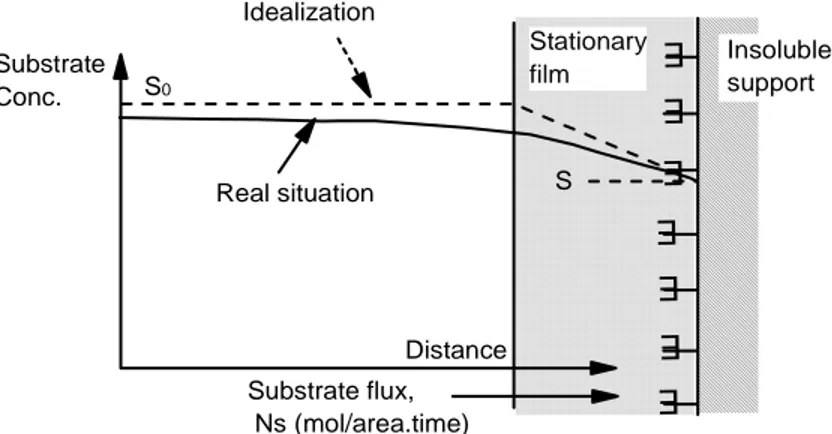
1.12 Enzyme immobilized on the surface
For the enzyme immobilized on the surface, a stationary film also called Nerst diffusion layer, is formed, attached to the enzyme-membrane surface. This layer limits the diffusion of the substrate and for this reason the concentration of the substrate in the bulk solution decreases near the immobilized enzyme matrix. At the steady state, at the interface, the mass transfer of the substrate is balanced from the reaction and consequently from the substrate consumption. In this case the Michaelis-Menten equation take into account the different substrate concentration in the bulk solution and near the surface:
Fig. 1.17 Schematic representation of transport for catalyst immobilized on the surface
of insoluble support E E E E E E E Insoluble support Stationary film S S0 Substrate Conc. Distance Substrate flux, Ns (mol/area.time) Idealization Real situation
Introduction to membranes and membrane bioreactors 35
[ ]
[ ]
S K S V S S k J m s s + = − = max 0 ) ( ………..………..(Eq 1.7)In this equation S and S0 are the substrate concentration in the bulk and at the immobilized enzyme interface respectively and ks is the mass transfer coefficient. The ratio between the maximum reaction rate and maximum mass transfer rate is given by the Damköhler number which can be written in the form of:
0 max S k V Da s = ………..………….(Eq: 1.8) Two different phenomenon can be derived from this equation. Those are :
If Da <<1 the transfer rate is larger than the reaction rate, and this means that the system works at a low mass transfer resistance. This is the case known as reaction limited regime. In this system the following equation:
[ ]
[ ]
b m b kin S K S V V + = max ………..(Eq: 1.9) can be assumed.If Da >> 1, the reaction rate is larger than the mass transfer, this is the case known as diffusion-limited regime and Vdiff = ks [S]b .
The Damköhler number is also the ration between Vmax/Km to ks , Vmax/Km is also the slope of 1/V0 versus 1/ Km and ks is the slope of Vdiff versus Sb.
The mass transfer influence on the reaction is represented from the factor η: