U
NIVERSITÀ DELLA
C
ALABRIA
Dipartimento di Elettronica,
Informatica e Sistemistica
Dottorato di Ricerca in
Ingegneria dei Sistemi e Informatica
XXIII ciclo
Tesi di Dottorato
Agent architectures for modelling and
parallel simulation of complex systems
I would like to thank prof. Libero Nigro for his professionalism and dedication with which he supervised my research work.
I acknowledge all my colleagues at L.I.S., and especially Ing. Franco Ci-cirelli for its nearness and friendship during my PHD activity.
I would like to thank my family and my friends who have always sustained me in the important situations of my life.
Finally, I thank also the group ’precari invisibili della ricerca’ which keeps the fight alive with passion and intelligence.
A fundamental step in systems engineering lifecycle is represented by require-ments specification and thorough property analysis before proceeding with design down to the implementation phase. What are needed are suitable mod-elling languages able to ensure the necessary rigor in the expression of system behaviour. Property analysis can hopefully be based on exhaustive verifica-tion (e.g. by model checking) but more often has to resort to techniques such as discrete-event simulation (DES) which although is unable to reproduce the full execution state graph of a modelled system, can anyway provide valuable insights in the functional and behavioural properties of a system.
Modelling and analysis get further complicated when dealing with large-scale systems, like telecommunication systems, biological or social or eco-nomic systems, artificial intelligence systems, weather forecasting systems and so forth, which normally can only be studied through simulation. Such systems challenge for the avalability of adequate modelling languages, run-time executive infrastructures and powerful computing architectures for high-performance execution.
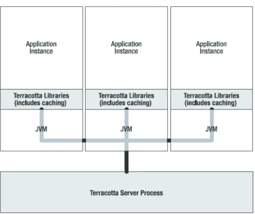
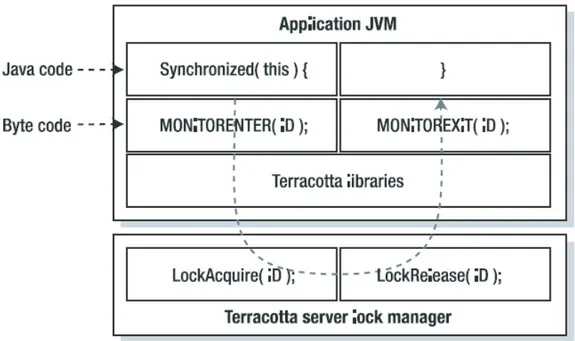
Nowadays, agent-based computing is often regarded as a very promising paradigm for modelling and simulation (M&S) of complex systems. Agents are typically encapsulated software entities which can naturally be associ-ated to system components, and interact and coordinate to one another to-wards the achievement of a common goal (system mission or emerging be-havior from agent individual bebe-haviors). Agents favour software modularity and reusability and can allow an exploitation of e.g. a distributed execution context. Although exist several agent-based modelling languages and tools, this work argues that solutions are often unsatisfactory to provide the flexi-bility and the execution performance required by complex systems M&S. This PHD thesis develops some M&S solutions based on a particular agent-based framework in Java -Theatre- proposed in the Software Engineering Laboratory (www.lis.deis.unical.it), headed by Prof. L. Nigro, of the Department of Infor-matics Electronics and Systems Science of the University of Calabria. Theatre is a light-weight architecture centred on the actor computational model. It
characterizes by its ability to support a huge number of agents in a simulation model, and to work with different transport layers and standard or emerging middleware like HLA or Terracotta. Theatre can effectively be used for M&S of large and scalable systems, and can act as an efficient runtime system for supporting several formal modelling languages. Specific contributions of this thesis are in the following areas:
- customizing Theatre for supporting hierarchical actors and statecharts,
thus controlling the explosion of states in situations where even at the agent level the dynamic behavior becomes complex
- experimenting with Theatre for supporting DEVS particularly in the case
of simulator interoperability by web services
- using Theatre for distributing RePast models for high-performance
simu-lation of complex agent-based systems over HLA/RTI
- developing a Theatre kernel on top of Terracotta to enable
parallel/dis-tributed simulation of large systems on a multi-core cluster
- evaluating the use of Theatre in supporting spatial environments
organi-zations in situated multi-agent systems.
The thesis is structured in 6 chapters as follows.
Chapter 1 is devoted to a presentation of fundamental concepts of agent-based computing.
Chapter 2 focuses on some exemplar M&S formalisms, HLA and Terra-cotta middleware for parallel/distributed simulation, and to well-known agent-based toolkits like RePast. The chapter covers also basics of aspect oriented programming.
Chapter 3 presents the Theatre actor-based architecture and reports some experience in M&S of variable structure systems. In addition details of a mapping of Theatre on HLA are discussed and applied in the context of a conservative time management algorithm.
Chapter 4 describes two particular developments: (a) statecharts based actors and (b) a DEVS implementation in terms of Theatre.
Chapter 5 illustrates an actor kernel based on Terracotta and reports about its performance using a multi-core cluster.
Chapter 6 presents some techniques for handling spatial environment par-titioning of situated multi-agent systems. The chapter also focuses on a software engineering project and its concretization, concerning the distri-bution of RePast agent models using the Theatre architecture over HLA.
1 Concepts of Agent-based Computing . . . 1 1.1 Introduction . . . 1 1.2 Agent metaphor. . . 2 1.3 Architectures . . . 5 1.3.1 Deliberative Architectures. . . 5 1.3.2 Reactive Architectures . . . 6 1.3.3 Hybrid Architectures . . . 8 1.4 Foundation technologies. . . 9 1.4.1 Agent platforms. . . 9 1.5 Mobile agents. . . 11
1.5.1 Benefits of mobile agents. . . 11
1.5.2 Mobile agents technology. . . 12
1.6 Distributed agent-based simulation . . . 14
1.6.1 Discrete-event simulation. . . 14
1.6.2 Distributed simulation . . . 14
1.6.3 The problem of shared state . . . 15
1.7 Conclusions. . . 16
2 M&S formalisms, middleware, tools. . . 17
2.1 Introduction . . . 17 2.2 Formalisms . . . 18 2.2.1 DEVS . . . 18 2.2.2 Statecharts. . . 21 2.3 Middleware. . . 25 2.3.1 HLA-RTI. . . 25 2.3.2 Terracotta. . . 29 2.4 Tools . . . 34 2.4.1 RePast. . . 34
3 The Theatre architecture. . . 43
3.1 Introduction . . . 43
3.2 Theatre basics . . . 44
3.2.1 Actor modeling and behavior . . . 44
3.2.2 Structure of a theatre. . . 46
3.2.3 Agent naming. . . 46
3.2.4 Agent migration. . . 47
3.2.5 Dynamic model reconfiguration . . . 48
3.3 Theatre on top of HLA. . . 48
3.3.1 Time management. . . 50
3.3.2 Lifecycle of a Theatre-based mederation . . . 50
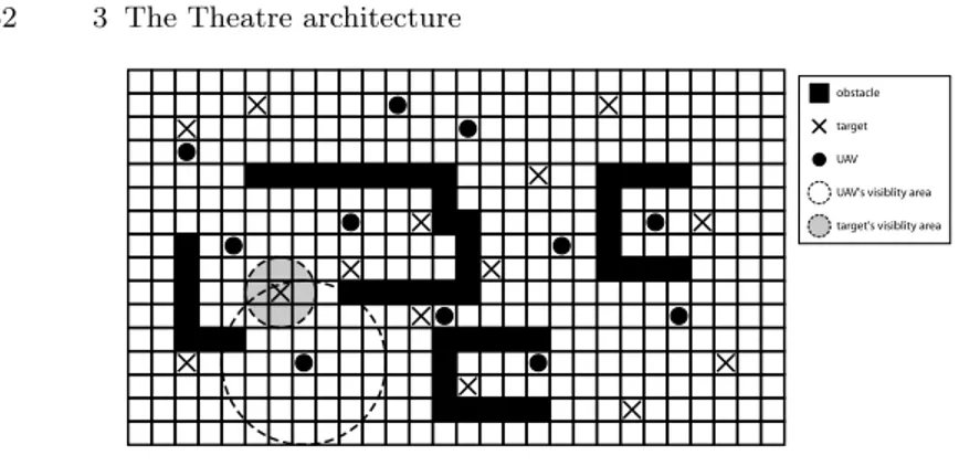
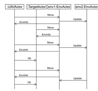
3.3.3 An UAV modeling and simulation example . . . 51
3.3.4 Experimental mesults. . . 59
3.3.5 Model scaling and simulation performance. . . 61
3.3.6 Related work . . . 63
4 Supporting M&S formalisms through Theatre . . . 67
4.1 Introduction . . . 67
4.2 Hierarchical actors. . . 67
4.2.1 A modelling example . . . 68
4.3 Actors for DEVS M&S. . . 75
4.3.1 ActorDEVS . . . 75
4.3.2 DEVS-WORLD Vision. . . 77
4.3.3 Wrapping ActorDEVS in DEVS-WORLD . . . 79
4.3.4 Variable structure system example. . . 84
4.3.5 Configuration, deployment and simulation. . . 86
5 Theatre over Terracotta . . . 89
5.1 Introduction . . . 89
5.2 Design issues. . . 90
5.3 A Predator/Prey model . . . 94
5.3.1 Greedy strategy (str1) . . . 94
5.3.2 Minority game strategy (str2). . . 95
5.3.3 EnvActor behavior . . . 97
5.4 Simulation experiments . . . 98
5.4.1 Strategies performance. . . 99
5.4.2 Simulation performance. . . 100
6 Distributing situated multi-agent systems. . . 105
6.1 Introduction . . . 105
6.2 Distributing spatial environments. . . 107
6.2.1 The problem of distributed shared state. . . 108
6.2.2 A mechanism for conflict resolution. . . 110
6.3 Using time as a tie-breaking mechanism . . . 112
6.3.2 Consistency among updates: adding the step slot. . . 114
6.3.3 Multiple events at the same virtual-time: adding the epoch slot . . . 114
6.3.4 Remote operations . . . 115
6.4 Supplying stage to actors in Theatres . . . 115
6.5 Distributing RePast on top of Theatre . . . 118
6.5.1 Related work . . . 118
6.5.2 Inside RePast. . . 119
6.5.3 HLA ACTOR REPAST Design Issues . . . 121
6.5.4 Tileworld Model Example . . . 128
6.5.5 Simulation experiments . . . 130
Conclusions and Outlook . . . 135
Concepts of Agent-based Computing
1.1 Introduction
Agent-based computing is a promising approach for the development of appli-cations in complex and distributed scenarios where no global control is pos-sible. It provides a way to design and develop software applications in terms of autonomous entities, referred to as agents, which are situated in an envi-ronment and flexibly can achieve their goals by interacting to one another by
means of high-level protocols and languages [Jen01,OZ04]. Compared to other
computing paradigms, agent-based computing can be defined as evolutionary,
however in terms of practical usage it appears to be revolutionary [Lev04].
Currently, agents are the focus of intense interest in many sub-fields of computer science and artificial intelligence. Agents are being used in an
in-creasingly and incredible wide variety of applications [LMP04,JW98], ranging
from comparatively small systems such as email filters to large, open, com-plex, mission-critical systems such as air traffic control. Knowledge Manage-ment, Team Working, Bio-Inspired Architecture, Supply Chain ManageManage-ment, Entertainment and Health Care are growing areas for agent research and de-velopment, especially when complex interactions among entities in the same environment make it extremely difficult to understand and thoroughly analyse system behaviour.
An agent is a high-level software abstraction which is a key for modern software because: (i) the autonomy of application components reflects the intrinsically decentralised nature of distributed systems and can be considered as the natural evolution of notions like modularity and encapsulation; (ii) the flexible way in which agents operate and interact (both with each other and with the environment) is suited to the dynamic and unpredictable scenarios where software is expected to operate.
Although in widespread use, agent computing cannot be considered as a panacea in computer science: nothing that can be done with agents cannot
be done with other means [HCK97,WJ98]. However, research areas involved
of potential advantages [Jen01, HCK97, Pic01, Lev04, GKCR00, BHR+02,
Bra97] of this approach.
The chapter is structured as follows. Section 1.2 provides basic
defini-tions and concepts related to the agent metaphor. A discussion about agent
architectures is provided in section1.3.1.4offer a survey on some
methodolo-gies, technologies and infrastructures relevant to the agent paradigm. Finally, conclusions are presented with an indication of current directions in agent research.
1.2 Agent metaphor
The term agent literally means one that acts or one that does something
[Woo02] and it origins from the dog latin to do. A tacit assumption is
that agents take an active role and originate actions that can affect their environment, rather than passively allowing their environment to affect them. Even if the above definition is very simple and clear, there is no general consensus on what software agents really are. Probably this is due to the sheer
breadth of subject areas in which agents are being applied (see section1.1).
The concept of agent can be traced back to in the 1970s to Carl
He-witts concurrent Actor model [Hew77a]. In this model, Hewitt proposed a
self-contained, interactive and concurrently executing object which he termed actor. This object has some encapsulated internal state and can respond to messages coming from other similar objects.
Above statement provides an operational definition of an agent but it owns a low level of abstraction in describing agent behaviour. Franklin and
Graesser [FG97] critically reviewed a number of agent definitions showing
that none of them is perfect or complete. Bradshaw [Bra97] instead
charac-terises agents in terms of ascriptions and descriptions. A classical definition
of agent is owed to Wooldrige and Jennings [WJ95]:
...the term agent is used to denote a hardware or (more usually) software-based computer system that enjoys the following properties:
autonomy: agents operate without direct intervention of humans or oth-ers, and have some kind of control over their actions and internal state social ability: agents interact with other agents (and possibly humans)
via some kind of agent-communication language
reactivity: agents perceive their environment (which may be the physical world, a user via a graphical user interface, a collection of other agents, the INTERNET, or perhaps all of these combined) and respond in a timely fashion to changes that occur in the environment.
This provide the so called weak definition of an agent. However for some researchers the term agent has a stronger and more specific meaning than that
sketched out above, so in a strong definition, an agent can hold also some of the following properties:
mobility: the ability of an agent to move across a network
veracity: the assumption that an agent will not knowingly communicate false information
benevolence: the assumption that agents do not have conflicting goals, and that every agent will therefore always try to do what is asked to it rationality: (crudely) the assumption that an agent will act in order to
achieve its goals, and will not act in such a way to prevent its goals being achieved at least insofar as its beliefs permit.
An agent (see figure1.1) can be viewed as a problem-solving entity with
well-defined boundaries and interfaces [Jen01] that can act on behalf of an
user, another agent or itself. Agents are situated (or better embedded) in an environment upon which they have partial control and partial observability. An agent senses the environment through sensors and acts on it through ac-tuators. Autonomy means that agents can choose how and if respond to some external stimuli. In other words an agent can say no if it wants. Reactive-ness and proactivity mean instead that an agent is able to respond in a timely fashion to external changes that occur in it’s environment and take initiatives. An environment provides the conditions under which an agent can exist and it defines the properties of the world (e.g., laws, rules, constraints and policies) in which an agent will function. Agents may also use the environment as communication channel to exchange messages to one another (see section ??). It’s important to describe precisely such an environment since a slight change in it can impact the results of the agent system in an unpredictable way. Environment attributes include accessibility, determinism, diversity, con-trollability, volatility. Each of them heavily affects agent behaviour and capa-bilities. Currently there are no standardised way to describe these important
features, and to clearly differentiate them from the agent code [Lev04].
In adopting an agent-oriented view, it soon becomes clear that modelling or dealing with most problems requires or involves more than one single agent. The issue is to choose many simpler and smaller agents or a reduced
Environment Sphere of visibility and influence organisational relationship interaction agent
Fig. 1.2. A canonical view of a MAS
number of more complex agents. It’s impossible to give an ultimate answer to this question. It depends on, for instances, to the intrinsic nature of the problem to solve, to the degree of modularity and the abstraction level, the kind and number of relations occurring among system entities, the kind of properties that are required to study or to emphasize, the expertise of the system developer. A system in which multiple agents are involved is usually referred to as a Multi Agent System (MAS):
...[an agent] is in a multi-agent system (MAS) that contains an environ-ment, objects and agents (the agents being the only ones to act), relations among all the entities, a set of operations that can be performed by the
en-tities and the changes of the universe in time and due to these actions [Fer99].
A MAS can be viewed as a loosely coupled network of problem solvers (i.e., agents) that interact to solve problems that are beyond the individual capabilities or knowledge of each problem solver which in turn has only a lim-ited viewpoint of the problems themself. In a such system there is no global control, data are decentralised and computation is intrinsically asynchronous. Improving system reliability, availability and efficiency are some of the
advan-tages in using a MAS (see [Syc98]). A MAS, however, is more than a bunch
of agents which merely interact. Agents can form societies in which every
participant exhibits roles and owns rules (see figure1.2).
Agent interactions can vary from simple semantic operations (for instance through traditional client/server communications) to rich social interactions (i.e., the ability to cooperate, coordinate, and negotiate about a course of actions). An agent communication language (see section ??) permits to main-tain relationships among agent acquaintances and, as in human society, these relationships are dynamic: they can evolve, change or be broken.
The notion of an environment, together with social ability, are key features which distinguish agent-based computing from other computing paradigms
like Object Oriented Programming [Lev04, Woo97]. With respect to other
paradigms, the agent metaphor provides a convenient and powerful way to properly describe real world pictures and to deal with scenarios in which
collective behaviour and interaction may produce emerging properties that
cannot be achieved by single entities [NNS05,SS03,BSdS+05]. It’s also
effec-tive in systems with high runtime uncertainty or incomplete information (e.g., telecommunication service across multiple providers) and when, in a dynamic environment, there are some decisions to take based on multiple sources and large amounts of data (e.g., e-markets, logistics).
Further agent disquisition should require at this point to speak about agent classification and agent taxonomy. Agents can be better qualified in term of their purposes and their behaviours like degree of mobility, degree of autonomy and so forth. These issues are beyond the scope of this chapter, the
reader is referred to [FG97,Bra97,Nwa96].
1.3 Architectures
Agent architectures can be thought of as software engineering models of agents. Research in this area is concerned with the problem of designing software or hardware systems that will support various agent properties and behaviours.
Maes [Mae91] defines an agent architecture as a methodology for building
agents which specifies how agents can be decomposed into a set of interacting modules whose aim is to model how perceptions and the internal state of an agent may determine an action and changes in the agent state. Agent
architecture can be divided in three broad categories [WJ95]: deliberative,
reactive and hybrid. The proposals are fundamentally different in their view
of the term ofintelligence.
1.3.1 Deliberative Architectures
Rely on the reduction of the world to a representation of realisable symbols that can be combined to form structures upon which processes can be executed
to operate upon the symbols according to a coded set of instructions [NS76].
Decision regarding actions to perform are made via logical reasoning, pattern matching and symbolic manipulation. From a theoretical point of view two issues exist. The first one concerns translating the real world in an accurate, adequate and useful symbolic representation (transduction problem), the sec-ond one concerns on how symbolically represent information about real-world entities and process, and how to get agents to reason upon these information (representation/reasoning problem).
The idea of having a deliberative agent, i.e., able to exhibit a rational
behaviour, is very attractive but, from a practical point of view, it is difficult
to build useful symbol manipulation algorithms that will be guaranteed to terminate with useful results in an acceptable time bound.
A particular type of deliberative architecture, perhaps the most known
example, is the BDI architecture [BIP88,RG95], which is founded on rational
Intention. The BDI architecture draws its inspiration from the philosophical
theories of Bratman [BIP88] who argues that intentions play a significant
and distinct role in practical reasoning that cannot be reduced only to beliefs and desires. Beliefs, desires and intentions represent respectively the informa-tion, motivational and deliberative states of an agent. These mental attitudes determine the system behaviour and are critical for achieving adequate or optimal performance when deliberation is subject to resource bounds.
Beliefs can be viewed as the informative components of system state which has to be appropriately kept updated after each sensing action.
An agent requires also to have information about the objectives (or de-sires) to be accomplished and, more generally, what priorities and payoff are associated with them. Unlike the system beliefs, these information are usually generated instantaneously, or functionally, without requiring any state repre-sentation. This component is representative of system desires which can be thought of as representing the motivational state of the system or what an agent wishes to become true. Adopted desires are often called goals.
Taken actions, or changes into environment, may affect system beliefs and desires. Thus it becomes necessary to include a component into system state to represent the currently chosen course of actions. This additional state com-ponent represents the agent intentions which, in essence, capture the delib-erative component of an agent system or what an agent will try to make true. An intension also captures the notion of commitment with respect to a previous decision. A commitment embodies the balance between reactivity and goal directedness of an agent-oriented system. Static and dynamic
con-straints [RG95] may be added to relate together beliefs, desires and intentions
in order to characterise agent behaviour. These constraints, for instances, are particularly important to ensure stability when frequent changes occur into the agent environment.
A whole range of practical development efforts related to BDI systems have
been undertaken. These include for instances IRMA [BIP88], COSY [BS92]
and GRATE* [Jen93] which are all reviewed in [HS96]. Deepening on
BDI-architecture, and related BDI-logic, can be found instead in [RG91,Rao95].
1.3.2 Reactive Architectures
They rely on the basic and fundamental assumption that intelligent
be-haviour may be achieved without using complex symbolic representations
[Bro90,Bro91a,Bro91b]. Intelligence is assumed to be an emergent property of certain complex systems which arises as a result of interactions among agents and interactions between agents and their environment. This philoso-phy presumes that real intelligence exists only in the real world and it is not in disembodied systems such as theorem provers or expert systems.
Explicit symbolic models and symbolic reasoning mechanisms disappear within reactive architectures which in turn provide an opposed point of view with respect to deliberative architectures.
One of the first, and most known, reactive architecture is the subsumption
architecture [Bro86].
A subsumption architecture is a hierarchy of possible concurrent
task-accomplishing behaviours. Each behaviourcompetes with the others to
ex-ercise control over agent activities. Lower layers represent more primitive kinds of competences (such as obstacle avoidance in a scout agent ) and have prece-dence over layers further up in the hierarchy which offer some increasingly more abstract behaviour like identifying objects, taking decisions and so forth
(see figure1.3).
A layer L1 is unaware of the existence of a possible upper layer L2. L2 in turn is able to examine data coming from L1 and injects data into it
suppressing the normal data flow. In such a schema additionalblocks can
be easily added without changes into the initial working system. All of this
fosters an aspect oriented programming style [EFB01] in defining the whole
agent behaviour in which every layer has an asymmetric knowledge about the other one.
A subsumption architecture offers an horizontal slicing of control aspects
which contrasts classical functional decompositions [Bro86] in which every
module (or layer) has to be entirely traversed in order to take an action,
for instance, after sensing some changes into the environment.
By using this approach the resulting systems are very simple and efficient in terms of the amount of computational resources needed. A subsumption architecture fosters also robustness because a fail into a higher layer could not impair lower layer functionalities. However, against to these benefits, agents with many behaviours may become undoable and if more layers are used then more difficult is understanding what is going on.
Another different way for building reactive agents bases on the situated
automata approach [RK95]. By using this approach an agent is viewed as an
automaton which, on sensory input, takes an action and changes its current state to a new state. Each agent is first specified in terms of a declarative formalism and then this specification is translated into a low-level digital
ma-Layer 0 Layer 1 Layer 2
Sensors Actuators
chine which satisfies the declarative specification. The machine can operate in a provably time-bounded fashion because it does not use any symbol ma-nipulation. At runtime the agents are purely reactive.
The situated automata approach is not intended to replace deliberative ar-chitectures. It allows one to describe the informational content of an agent’s computational state in a semantically rigorous way without requiring a com-mitment to conventional run-time symbolic processing. This is suitable to the development of so called situated agents whose characteristic is in their close interaction with the environment in which they are situated. Adopting this
view, the fundamental phenomena to be explained is not thereasoning but
the mutual constraints exhibited among parts of a physical system over time.
Further reading may be found in [RK95,WJ95,BMS02].
1.3.3 Hybrid Architectures
They rely on the assumption that neither a completely deliberative nor com-pletely reactive approach is adequate for building agents. An hybrid approach results from combining best elements of both reactive and declarative systems. From this perspective an agent can be composed of two (or more) subsys-tems: a deliberative one, containing a symbolic world model, which develops plans and takes decisions, and a reactive one which is capable of reacting to events that occur in the environment without engaging complex reasoning. The reactive component may exhibit a kind of precedence over the deliberative one, so that it can provide a rapid response time to important environmental events. This kind of structuring leads naturally to the idea of a layered archi-tecture where major issues are related to better understanding relationships and interdependences occurring among layers.
One of the most known hybrid architecture (see [WJ95]) is the
Procedu-ral Reasoning System (PRS) which is considered the best established agent
architecture currently available. Originally described in [GL87], this
archi-tecture has progressed from an experimental LISP version to a fully fledged C++ implementation known as the distributed Multi-Agent Reasoning Sys-tem (dMARS), which has been used in most significant multi-agent
applica-tions [GR96]. As an example, Oasis is a system for air traffic management
that addresses issues of aircraft scheduling, comparing actual progress with established sequences of aircrafts, estimating delays, and notifying controllers to correct deviations. Oasis successfully completed operational tests at Sydney Airport in 1995.
The PRS architecture has its conceptual roots in the belief-desire-intention (BDI) model. In tandem with the evolution of the PRS architecture into an industrial-strength production architecture, the theoretical foundations of the
BDI model have also been closely investigated (see [RG95]).
Using dMARS architecture (see figure1.4), the BDI model is made
B eliefs Desires P lan Library Interpreter Intentions S ensor Input Action Output
Fig. 1.4. dMARS architecture
courses of actions that may be undertaken by an agent in order to achieve its intentions. An agent plan library represents its procedural knowledge.
Each plan contains several components: (i) a trigger or invocation condition which specifies the circumstances under which the plan should be considered, (ii) a plan context, or pre-condition, specifying the circumstances under which the execution of the plan may commence, (iii) a maintenance condition char-acterising the circumstances that must remain true while the plan is executing, (iv) a body defining a potentially quite complex course of actions, which may consist of both goals (or subgoals) and primitive actions. Primitive actions
can be thought of as procedure calls. An interpreter (figure1.4) is responsible
for managing the overall operations of the agent.
Further details about dMARS architecture may be found in [DLG+04].
1.4 Foundation technologies
As stated in previous sections, agent based computing appears to be very useful in many different and heterogenous contexts. For instance, the usage of agent systems to simulate real-world domains may provide answers to complex physical or social problems otherwise very hard do obtain or practically unob-tainable (e.g., modelling the impacts of climate changes on various biological populations, or modelling the impact of public policy options on social or eco-nomic behaviours). However the characteristics making the agent metaphor very appealing require to be supported and implemented. As a consequence many links exist between the agent metaphor and other disciplines considered
as sources of so called foundation technologies exploitable for
support-ing mobility, social ability and so forth. A survey on some of these topics is
reported in [LMP04,LMSW05].
1.4.1 Agent platforms
An agent platform can be viewed as middleware layer providing a platform-independent execution locus in which software agents may act. It provides
support for software agents to execute, to manage their execution, to access system resources, and to guarantee integrity and protection of agents and the platform itself. Agent platforms also support migration, naming, location and communication services. They may enable methodologies and offer tools which aid in developing a multi-agent system.
This section may be considered as a complement to section 1.3 where
agent architectures are introduced and where an architecture taxonomy is reported on the basis of the agent rational behaviours. Here agent platforms are differentiated on the basis of offered functionalities.
A very large number of agent platforms, coming either from academia or industrial contexts and often developed using Java technologies, exist today. Attempts to standardise agent platforms have resulted in the establishment
of two main standards, MASIF [MBB+99] and FIPA [FIP]. Agents belonging
to specific platforms affiliating to these standards can collaborate in achieving common goals via inter-agent messaging. However, agents can only migrate to and execute in remote sites only if the site’s hosts run a compatible agent platform and the agent has the credentials to surpass the site security checks. This means that the concept of agents freely roaming Internet sites performing tasks on behalf of the user is yet unrealistic.
Jade [BR01] from TLAB, is an open source platform for peer-to-peer agent
based applications fully implemented in Java. Jade simplifies the implemen-tation of multi-agent systems through a middleware that complies with the
FIPA specifications [FIP] and through a set of graphical tools that supports
the debugging and deployment phases. System configuration is achieved by means of a remote GUI.
JACK [HRHL01] is an example of commercial agent platform. It
incorpo-rates a suite of graphical tools, targeted at analysts as well as programmers, suitable for building, running and integrating commercial-grade multi-agent systems using a component-based approach. Agent development rely on the JACK Agent Language which extends Java with agent-oriented concepts.
The JAMES platform [SBS00] instead, pays attention to agent system
fault tolerance issues [OWB04, FD02]. It provides schemes for error
detec-tion, checkpointing and restarting failed agents, as well as a reliable migration protocol that deals with network partitioning.
Notable cornerstones of agent platform work include Actor
Foundry [VA01a] based on the Gul Agha Actor model [Agh86], Aglets
from IBM [DM98], Mole from the University of Stuttgart [BHR+02],
Concordia [WPW+97], TACOMA from the Universities of Tromso and
Cornell [JLvR+02], Grasshopper from IKV [BBCM98], as well as D´Agents
from Dartmouth College [GCK+02b] and Voyager [Gla98], though there are
1.5 Mobile agents
Mobile agents [Pic01,Ple99] provide a valuable alternative to the traditional
client/server programming model (among others), because they provide a uni-form paradigm for distributed systems. Nevertheless, mobile agent technology is not yet widespread in today’s applications. Conventional distributed sys-tems typically assume a static configuration of the environment where the distributed application executes. Communication among a set of hosts is en-abled by physical links whose configuration is fixed and statically determined. Similarly, the various portions of the distributed applications that run on the nodes of the system are typically bound to such nodes for their whole life. This view is being challenged by technical developments that introduce a degree of mobility in the distributed system. The so called code mobility allows for the code and possibly the state of an executing program to be migrated, in part or as a whole, at run-time. The paradigm of mobile code generalizes this concept by performing changes along two orthogonal axes:
Where is the know-how of the service located? Who provides the computational resources?
Depending on the choices made on the server and client sides, the following
additional paradigms can be identified [FPV98]]:
Remote Evaluation (REV). In the REV paradigm a component A sends instructions specifying how to perform a service to a component B. The instructions can, for instance, be expressed in Java bytecode. B then executes the request using its resources.
Code on Demand (CoD). In the CoD paradigm the same interactions take place as in REV. The difference is that component A has the resources collocated with itself but lacks the knowledge of how to access and process these resources. It gets this information from component B. As soon as A has the necessary know-how, it can start executing.
The mobile agent paradigm is an extension of the REV paradigm. Whereas the latter focuses primarily on the transfer of code, the mobile agent paradigm involves the mobility of an entire computational entity, along with its code, state, and potentially resources required to solve the task.
1.5.1 Benefits of mobile agents
In the following some advantages of mobile agent computing are described: Reduced bandwidth consumption. The ability to migrate can be used to
achieve co-location among agents and resources they must access in or-der to reduce the need for remote communication. In addition, a seman-tic compression concept can be realized. Semanseman-tic compression reduces the amount of information being transmitted by filtering it at the source,
based on its content. This is dramatically different from the client/server approach where an unfiltered over-set of information transit on the net. In mobile agent approach, a filtering agent is sent on the server in order to send back only the data that is really useful to client. The locality of the communicating entities allows to decrease the latency and save band-width. Clearly the gain in latency and bandwidth must overcome the cost of sending the agent to the server node.
Improved fault tolerance. In conventional systems, a high-level interaction between a client and a server involves a series of pairwise low-level interac-tions under the form of requests and replies. During these interacinterac-tions, the state of the overall computation is distributed. This fact heavily compli-cates the task of recovering from a fault, due to the distributed consensus problem. In mobile agent approach, agents embedding the code describing the whole high-level interaction can migrate on the server. Thus the state of interaction remains local, and faults can be dealt with easily.
Support for disconnected operations. Mobile agents can carry out their tasks autonomously and independently of the application that dispatched them. This capability, that is at the core of many of the advantages mobile agents provide, is particularly useful in scenarios characterized by physical mobility, where the constraints posed by terminals and communication links often force the user to disconnect from the network to perform some task on behalf of a user, who meanwhile is totally disconnected. Results can be eventually gathered by the user upon reconnection.
Protocol encapsulation. Mobile agents allow a packet of information to travel within the system together with the application logic needed to interpret and manipulate it. This improves the flexibility of the system, simplifying the deployment of different, co-existing policies for using data. Load balancing. An overloaded host (in terms of cpu and memory
utiliza-tion) can migrate a part of his agents toward low loaded hosts.
1.5.2 Mobile agents technology
Technology has traditionally been the main focus of research on mobile agents. As a matter of fact, the term ’mobile agent’ was made popular by the
tele-script language [Whi99], developed by General Magic in 1994. The emphasis
on technology is witnessed, among the other things, by the large number of
systems contained in the Mobile Agent List [Hoha], maintained at the
univer-sity of Stuttgart, Germany, that provides an approximate census of existing mobile agent systems.
Mobile agent systems typically identify the agent with a unit of execution belonging to the lower layers of the virtual machine, e.g. a thread or a
pro-cess. A unit of execution [FPV98] is constituted by the code governing its
behaviour, the data associated with it and necessary to its computation, and by its execution state, e.g. program counter, and call stack.
Mobile agent systems allow migration of the whole unit or a part thereof, i.e. one or more of the three constituents mentioned above. The most rel-evant differences among existing systems lie exactly in what they allow to move, and how it is actually moved. A first distinction can be drawn based on whether the execution state is migrated along with the executing unit or not. Systems providing the former option are said to support strong migration, as opposed to systems that discard the execution state across migration, and are hence said to provide only weak migration. In this latter kind of systems, if the application requires the ability to retain the thread of control, extra pro-gramming is required in order to save manually the execution state. Instead, in systems supporting strong mobility, migration is completely transparent to the migrated entity, which resumes execution right after the migration instruction. Despite these advantages, most of the mobile agent systems sup-port only weak mobility. Example of systems that supsup-port strong mobility
are: Telescript, Tacoma [PS97], Ara [JvRS95], and D’Agents [GCK+02a].
Another dimension to understand the mechanisms supporting mobility is constituted by the strategies employed to relocate the code constituting the execution unit. Although a number of strategies are potentially mean-ingful and useful, the use of Java as an implementation language has often encouraged the designers of mobile agent systems towards mechanisms that are directly inspired by the Java class loader. under this scheme, only agent’s root class is migrated along with the agent; after migration, additional classes needed for execution of the agent are downloaded dynamically from the agent source host, or from some other code repository on the network. This
mecha-nism, adopted by many of the Java-based systems, notably Mole [BHR+02]
and Aglets [LO98], relies on the assumption that the code repository is
al-ways available, thus implicitly neglecting one of the main advantages of mobile agents, i.e. the ability to support disconnected operations. On the other hand, other systems, e.g. D’Agent, always ship the whole code base together with the agent, thus in many cases sending also classes that are used infrequently. Finally, the third dimension is constituted by the data the mobile agent may carry along during migration. The unit of execution running at the source is likely to contain bindings to resources (e.g. objects, files, other units) that are shared with other units on that host. To allow mobility of the executing unit requires both a mechanism and a policy to determine how these
bind-ings are handled upon migration. In [FPV98] a number of strategies are
showed. Essentially, the binding to a resource can be severed, retained, or re-estabilished with a different but compatible resource. When the binding is retained, two alternatives are possible: either the resource is migrated along with the agent, or the binding is stretched across the network by creating a network reference from the new host of the agent. When the binding is in-stead re-established to a new, compatible resource, such resource is typically constituted either by a copy of the original one, or by a stationary resource having the same type (e.g. a printer).
1.6 Distributed agent-based simulation
Simulation is the imitation of a system behaviour and structure in an ex-perimental model in order to studying emerging system properties which are transferable to reality. In multiagent-based simulation (MABS) real world sys-tems are modelled using multiple agents. A software agent is typically defined as a program that acts autonomously, communicates with other agents, is goal-oriented (pro-active) and uses explicit knowledge. The modelled system emerges by interaction of the individual agents as well as their collective be-haviour. Agents typically send messages according to some communication protocol.
However, the computational requirements of simulations of agent-based systems far exceed the capabilities of conventional sequential von Neumann computer systems. Each agent is typically a complex system in its own right (e.g. with sensing, planning, inference etc. capabilities), requiring considerable computational resources, and many agents may be required to investigate the behaviour of the system as a whole or even the behaviour of a single agent. One solution to this problem is to attempt to exploit the high degree of parallelism inherent in agent-based systems to parallelise the simulation. Decentralised, event-driven distributed simulation is particularly suitable for systems with inherent asynchronous parallelism, such as agent-based systems.
1.6.1 Discrete-event simulation
In discrete-event simulation the operation of a system is represented as a chronological sequence of events. Each event occurs at an instant in time and marks a change of state in the system. The simulation must keep track of current simulation time, in whatever measurement units are suitable for the system being modeled. The simulation maintains at least one list of simulation events. This is sometimes called the pending event set because it lists events that are pending as a result of previously simulated event but have yet to be simulated themselves. An event is described by the time at which it occurs and a type, indicating the code that will be used to simulate that event. Discrete event techniques have been used in a number of MAS simulators. For example,
the SPADES system [BGFL94] and the JAMES system [SU00] and RePast
[Hohb].
1.6.2 Distributed simulation
Distributed simulation addresses two key problems of existing MAS
simula-tions and simulators [Log07, PS09]: scalability and simulation re-use.
Dis-tributed simulation (along with conservative or optimistic algorithms for time
coordination and synchronization in the-large[Fuj00]) exploits the natural
best use of available computing resources, allowing agent researchers and de-velopers to run agent simulations in less time and/or investigate multi-agent systems which are simply too large to be effectively simulated on a single computer. Distribution also promotes inter-operability of simulators and sim-ulation components. No one simulator or testbed is, or can be, appropriate to all agents and environments. Investigating a particular problem therefore frequently entails the development of a new simulation. The effort required to develop a new simulation from scratch is considerable. There is therefore a strong incentive to reuse existing simulation components, toolkits and testbeds for a new problem.
In the last years there was an explosion of interest in distributed simulation as a strategic technology for linking simulation components of various types at multiple locations to create a common virtual environment.
1.6.3 The problem of shared state
While conventional distributed simulation can bring real benefits from an inter-operability point of view, the speedups that can be attained in practice (particularly for situated MAS) are often rather limited. The simulation of situated agents (e.g., robots situated in a physical environment, or characters in a computer game or interactive entertainment situated in a virtual envi-ronment) presents particular challenges which are not addressed by standard parallel discrete event simulation (PDES) models and techniques. While the modelling and simulation of agents, at least at a coarse grain, is relatively straightforward, it is harder to apply conventional PDES approaches to the simulation of the agents environment. In a conventional decentralised event-driven distributed simulation, the model is divided into a network of Logical Processes (LPs). Each LP maintains its own portion of the simulation state and LPs interact with each other in a small number of well defined ways. The topology of the simulation is determined by the topology of the simulated system and its decomposition into LPs, and is largely static.
In contrast, the interaction of agents in a situated MAS is often hard to predict in advance. Different kinds of agents have differing degrees of access to different parts of the environment at different times. The degree of access is dependent on the range of the agent sensors (read access) and the actions it can perform (write access). For example, what a mobile agent can sense is a function of the actions it performed in the past which is in turn a function of what it sensed in the past. As a result, it is difficult to predict which parts of the simulation state an agent can or will access without running the simulation. This makes it hard to determine an appropriate topology for a MAS simulation a priori, and simulations of MAS typically have a large shared state, the agents environment, which is only loosely associated with any particular process. This shared state can form a bottleneck, limiting the speedups that can be attained.
1.7 Conclusions
This chapter surveys basic concepts of agent oriented computing and get into focus about property of mobility and the use of agents in distributed simu-lation. Even if agent computing is considered useful for developing complex software systems, it is worth of note that adopting a technology in place of
another is a very important issue [WJ98]. For instance, agent computing is
not suitable in application domains where an high degree of orchestration, i.e., a strong centralized coordination, is required. Moreover, agents usually involves multiple threads which intrinsically introduce uncertainty in estab-lishing temporal behaviour of a software system.
Nowadays the adoption of agent technologies has not yet entered in the
mainstream of commercial and industrial organisations [LMSW05]. Probably
this is due to research area of agent technology which is still only in its infancy and to the lack of proven methodologies, tools and widely accepted standards. Much of the standardisation effort in the agent community fall in the Foun-dation of Intelligent and Physical Agent (FIPA) and the Object Management Group (OMG), which are the premier agent standardisation bodies.
In particular, FIPA is a promising organisation that promotes agent-based technology and the interoperability of its standards with other technologies. FIPA was officially accepted by the IEEE as its eleventh standards committee on June 2005.
Current research efforts (see [LMP04, LMSW05]) are mainly devoted to
cover previously stated holes. In particular, standardisation efforts appear to be very critic. Extending links with other disciplines (biology, economics, sociology, game theory, and so forth), whose techniques could be applied to agent systems, represents another main issue.
M&S formalisms, middleware, tools
2.1 Introduction
This chapter is organized into three parts dealing with some M&S formalisms, some standard or emerging middleware, some agent-based toolkits and related concept.
The size and complexity of systems which are usually modelled as dis-crete event systems (DESs) (e.g. communication networks, biological systems, weather forecasting, etc.) is ever increasing. Modelling and simulation of such systems is challenging in that it requires suitable specification languages and efficient simulation tools.
Many languages exist to cope with complexity issues. In the first part two
formalisms are discussed. First DEVS [ZPK00] are briefly reviewed which
are capable of ensuring the necessary rigor in the modelling phase and in particular Parallel DEVS (P-DEVS) which is highly recognized as a reference
point in M&S. The second formalism concerns statecharts [Har87, BRJ99]
that is an evolution of finite state machines that offer a nested state structure and other powerful mechanisms for specifying complex system.
In the second part of the chapter some common and standard middleware are examined which can effectively be used for modelling and distributed/-parallel simulation. More specifically the IEEE standard HLA/RTI and the emerging Terracotta architecture are discussed.
In the last part of the chapter some fundamental tools supporting agent-based software engineering are presented. In particular the focus is on the RePast toolkit which is representative of current state-of-art of agent-based M&S tools. In addition basic concepts of aspect oriented programming (AOP) are discussed, which are a key for solving some software engineering problems.
2.2 Formalisms
2.2.1 DEVS
The Discrete-Event System Specification (DEVS) is a well known formalism
[ZPK00] which enables the specification of discrete-event systems through
mathematical concepts borrowed from the systems theory. A system specifi-cation is characterised by a time base and proper sets of inputs, outputs and states, and functions for determining the next state and outputs on the basis of current state and input. The strength of the formalism is in the rigorous and systematic way through which the modeller has to proceed during the abstraction of the parameters and behaviour of the system model. After the abstraction phase, the specification can then be mapped onto a implementa-tion framework for simulaimplementa-tion and output analysis. In the classic DEVS for-malism, Atomic DEVS captures the system behaviour, while Coupled DEVS describes the structure of system.
In the following the extension to classic DEVS named Parallel DEVS is considered which is more expressive in capturing simultaneity and parallelism in component behaviour.
Atomic DEVS
In P-DEVS an atomic component specification (Atomic DEVS) is a structure M defined as
M =< X, S, Y, δint, δext, δcon, λ, ta > where
X is the set of input values S is a set of states
Y is the set of output values
δint: S → S is the internal transition function
δext: Q × Xb → S is the external transition function, where
Q = {(s, e)|s ∈ S, 0 ≤ e ≤ ta(s)} is is the set of total states e is the is the elapsed time since last transition
Xb denotes the collection of bags over X (in a bag some elements may
occur more than once)
δcon: Q × Xb→ S is the confluent transition function
ta : S → <+
0,∞ is the time advance function
The interpretation of the elements of M can be summarized as follows. At any time the system is in some state s ∈ S. The system can remain in s for the time duration (dwell-time) ta(s). ta(s) can be 0, in which case s is said a transitory state, or it can be ∞, in which case it is said a passive state because the system can remain forever in s if no external event interrupts. Provided no external event arrives, at the end of (supposed finite) time value ta(s),
the system moves to its next state s0 = δint(s) determined by the internal
transition function δint. In addition, just before making the internal transition,
its stay in s, the system can receive an external event x which can cause s to be exited earlier than ta(s). Let e ≤ ta(s) be the elapsed time since the enter time in s (or, equivalently, the time of last transition). The system then exits state
s moving to next state s0 = δext(s, e, x) determined by the external transition
function δext. As a particular case, the external event x can arrive when e =
ta(s). In this case two events occur simultaneously: the internal transition
event and the external transition event. The next state s0, in this collision
situation, is determined by the confluent transition function δcon. The default
behaviour of δcon first applies the internal transition function and then the
external transition function. This behaviour, though, can be redefined. After
entering state s0, the new time advance value ta(s0) is computed and the same
story continues. The presence of confluent transition function together with the presence of bags instead of normal sets qualify model as Parallel DEVS. P-DEVS allows multiple components to be activated and send their output to other (influences) components at the same time. It is worth noting that there is no way to generate an output directly from an external transition. An output can only occur just before an internal transition. To have an external transition cause an output without a delay, a transitory state can be entered from which the exiting internal transition is preceded by the generation of the output value.
In reality inputs arrive to a component through input ports and outputs are trasmitted externally through output ports. An input is thus a pair < inp, x > of an input port inp and an event x. Similarly, an output is a pair < outp, y > of an output port outp and symbol value y. Ports are topological entities which decouple components and favour reconfiguration.
Coupled DEVS
Basic models may be coupled to form a coupled model. A coupled model tells how to several component models connect each other and with the external environment to form a new model. A coupled model can itself be employed as a component in a larger model, thus giving rise to hierarchical construction. A coupled model contains the following information:
a set of components
a set of input ports from which external events are received a set of output ports through which external events are sent
These components can be synthesized together to create hierarchical models having external input and output ports. The coupling specification (see Fig.
2.1) consists of:
the external input coupling which connects input ports of the coupled model to one or more of the input ports of internal components, this directs inputs received by the the coupled model to designated component models
the external output coupling which connects output ports of internal com-ponents to output ports of the coupled model. Thus when an output is generated by a component it may be sent to a designated output port of the model and thus transmitted externally
the internal coupling which connects output ports of internal components to input ports of other internal components. When an input is generated by a component it may be sent to the input ports of designed components (in addition to being sent possibly to an output port of the component model
A coupled model is equivalent to a basic model in the DEVS formalism and can itself be employed in a larger coupled model. This shows the formalism is closed under coupling as required for hierarchical model construction. Ex-pressing a coupled model as an equivalent basic model hides logic by which components interact to yield an overall behaviour.
Fig. 2.1. Schema of a coupled model
DEVS tools
In the last years many toolkits and libraries have been developed for the DEVS
formalism. One of the most known is DEVSJAVA [ZS03]. The software is
writ-ten in Java and supports parallel execution on a uni-processor. It supports higher-level, application specific modeling. Models in DEVSJAVA can also be easily mapped to DEVS/HLA or DEVS/CORBA for distributed execution in combined logical/real-time settings. Other Java DEVS tools are: JAMES II
[JAM] that provides support for many different formalisms, among these
vari-ants of DEVS formalism (e.g., PDEVS) and JDEVS [FDB02]. DEVS/C++
[ZMKK96] based on the parallel DEVS formalism, is a modular
hierarchi-cal discrete event simulation environment implemented in C++. Other C++
DEVS tools are: PowerDEVS [KLP03] , ADEVS [ADE] and CD++ [CDP].
Besides tools is worth to note some important projects related to DEVS.
DEVS environment can significantly improve the performance of large-scale distributed modeling and simulation exercises. This project has its foundation
on the High Level Architecture. Another project, SimBeans [PSS99], employs
the system theoretic simulation modeling methodology of DEVS as formal, mathematical foundations for modular, hierarchical modeling and simulation and a component based software architecture based on Java and JavaBeans.
An integrated approach (eUDEVS) for M&S was proposed in
[RMDLCMZ09]. It characterises for the use of the DEVS formalism for
mak-ing an UML specification executable and analyzable by simulation. eUDEVS permits the modeller to start a project with UML diagram models which al-low to abstract system structure and behaviour. UML diagrams, including statecharts, are then mapped into the specific class of DEVS models named Finite and Deterministic DEVS (FD-DEVS) which are represented in an XML format. A transformed UML specification can be simulated using e.g. DEVS-JAVA
2.2.2 Statecharts
Statecharts [Har87,BRJ99] are an extension of classical state transition
dia-grams. Statecharts are used to model the dynamic behaviour of a component or a system. Statecharts are specifically used to define state-dependent be-haviour, or behaviour that varies depending on the state in which a model element is in. A statechart consists of states, linked by transitions. A state is a condition of a system in which it performs some activity or waits for an event. A transition is a relationship between two states which is triggered by some event, which performs certain actions or evaluations. The basic difference with classic state transition diagrams consists in the possibility of nesting a sub automaton within a (macro) state thus encouraging step-wise refinement of complex behaviour. In addition, a macro state can be and-decomposed for supporting a notion of concurrency. Statecharts have been successfully applied
to the design of reactive event-driven real-time systems [HP98,SR98,FNP06],
as well as to modelling and performance analysis, e.g. [VCA02, VCAA06].
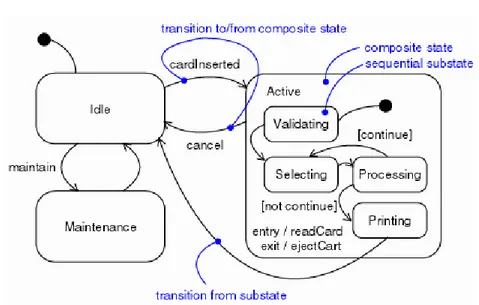
An example of a statechart diagram is shown in Figure2.2.
States
A state is a condition of a modelled system in which it performs some activity or waits for an event. A state has several properties:
name: A textual string which distinguishes the state from other states; a state may also be anonymous, meaning that it has no name.
entry/exit actions executed on entering and exiting the state.
internal transitions i.e. transitions that are handled without causing a change in state.
substates: the nested structure of a state, involving disjoint (sequentially active) or concurrent (concurrently active) substates.
Fig. 2.2. Statechart example
States are denoted by a rounded square symbol. As depicted in Figure
2.2, there are two special states that may be defined for a statechart. The
initial default state indicates the starting place for the statechart or substate. An initial state is depicted as reached by a pseudo-transition leaving from a filled black circle. final state indicates the completion of the execution of the state machine or that the enclosing state has been completed. A final state is represented as a filled black circle surrounded by an unfilled circle. Initial and final states are really pseudostates. Neither may have the usual parts of a normal state, except for a name. A state of statechart can recursively be decomposed into a set of sub states, in which case it is said to be a macro state. A state that is not decomposed is said to be a leaf state. The root state of the decomposition tree is the only one having no parent and it is referred to as the top state. This nested structure of states implies that system modelled by a statechart, at a given point in time, finds itself simultaneously in a set of states that constitutes a path leading from one of the leaf states to the top
state. Such a set of states is called a configuration [HN96]. A configuration is
uniquely characterised by the only leaf state which it contains.
Statecharts admit two types of state decomposition: or -decomposition and
and decomposition [HP98]. In the former case a state is split into a set of
sub states which are in an “exclusive-or” relation, i.e. if at a given time the modelled system is in a macro state it is also in exactly one of its sub states. In the other case sub states are related by logical “and”, i.e. if the modelled system is in a macro state it is also in all of its direct sub states, each of which acts as an independent concurrent component.
Transitions
A transition is a relationship between two states indicating that system in the first state will perform certain actions and enters a second state when a specified event occurs and stated conditions are satisfied. On such a change of state, the transition is said to ’fire’. Until the transition fires, the object is said to be in the ’source’ state; after it fires, it is said to be in the ’target’ state. A transition has several properties:
source state: the state affected by the transition; in a source state, an outgoing transition may fire on receiving the trigger event of the transition provided the guard condition, if any, is satisfied.
event trigger: the event that makes the transition eligible to fire (providing its guard condition is satisfied) when received by the object in the source state.
guard condition: a boolean expression that is evaluated when the transition is triggered by the reception of the event trigger; if the expression evaluates to true, the transition is firable; if the expression evaluates to false, the transition is disabled. If there is no other transition that could be triggered by the same event, the event is lost.
action: an executable atomic computation associated with the transition. target state: the state that is active after the completion of the transition. A transition may have multiple sources, in which case it represents a join from multiple concurrent states, as well as multiple targets, in which case it represents a fork to multiple concurrent states. An event is an occurrence of a stimulus that can trigger a state transition. Events may include signal events, call events, the passing of time, or a change in state. A signal or call may have parameters whose values are available to the transition, including expressions for the guard conditions and action. It is also possible to have a triggerless transition, represented by a transition with no event trigger. These transitions, also called completion transitions, is triggered implicitly when its source state has completed its activity. A guard condition is evaluated after the trigger event for the transition occurs. It is possible to have multiple transitions from the same source state and with the same event trigger, as long as the guard conditions don’t overlap. A guard condition is evaluated just once for the transition at the time the event occurs. The boolean expression may reference the state of the object. An action cannot be interrupted by an event and therefore runs to completion. This is in contrast to an activity, which may be interrupted by arrival of other events. Actions may include operation calls, the creation or destruction of objects, or the sending of a signal to another object. In the case of sending a signal, the signal name is prefixed with the keyword ’send’. An internal transitions allow events to be handled within the state without leaving the state, thereby avoiding triggering entry or exit actions. Internal transitions may have events with parameters and guard conditions. State transitions are represented by edges with arrows.
Each transition is labelled by ev[guard]/action where ev is the trigger, guard the guard condition, and action the action to perform.
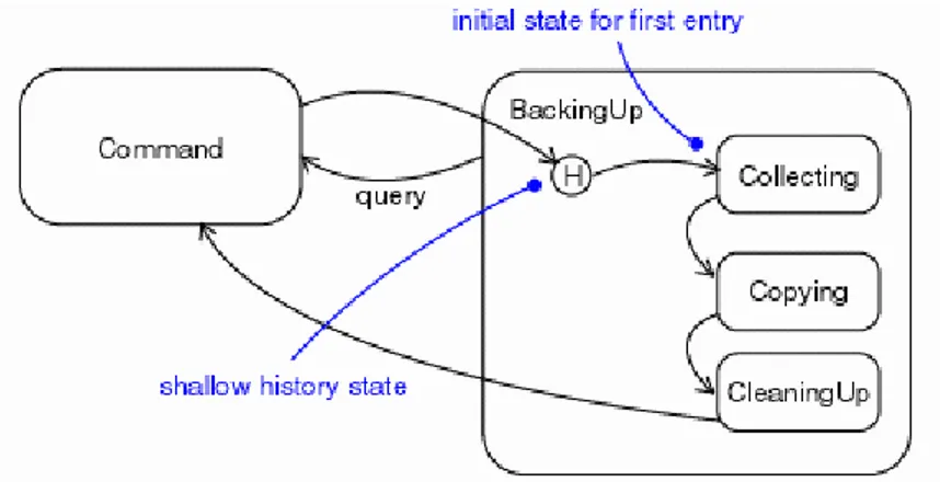
History pseudo-states
When a transition enters a composite state, the action of the nested state machine starts over again at the initial state (unless the transition targets a substate directly). History states allow the state machine to re-enter the last substate that was active prior to leaving the composite state. An example of
history state usage is presented in Figure2.3.
Fig. 2.3. History connector
This pseudostate is graphically identified by an history connector or H -connector. Such a connector is depicted as a small circle containing an H (shal-low history) or an H* (deep history), and it is always inside the boundary of a compound state. The difference between shallow and deep history concerns composite states with nesting level greater than one. With shallow history, when a macro state is left, only the directed substate is “remembered”. With deep history, instead, all configuration until the leaf state is kept in memory. More specifically, Let S be the destination state of a transition tr. The con-figuration which is assumed as consequence of firing tr depends on the way tr reaches S :
If S is a leaf state the new configuration is the only one that contains S. If S is a macro state and tr ends on its border, the next configuration
corresponds to the destination state being the initial state of S.
If S is a macro state and tr ends on a shallow history connector, the next configuration corresponds to the destination state being the state that is the history of S
Finally, if S is a macro state and tr ends on a deep history connector, the configuration depends on the nature of the state D which is currently
history of S. If D is a leaf state, the configuration will be the only one that contains D, otherwise the configuration corresponds to the case tr would end on a deep history connector of D.
2.3 Middleware
2.3.1 HLA-RTI
HLA (High Level Architecture) [KWD99,HLA], originally developed under
the leadership of the Defense Modeling and Simulation Office (DMSO), facil-itates reuse and interoperability among (possibly heterogeneous) simulations
[HLA]. HLA was accepted as an IEEE standard (IEEE 1516) in
Septem-ber 2000. HLA supports component-based simulation development, where the components are referred as federates that interact each other in order to form a combined simulation system known as federation. More specifically, a federation contains: the federates, a common object model specifying data exchanged between federates in federation, called Federation Object Model (FOM), and a supporting software for federation execution called RunTime Infrastructure (RTI).
HLA defines a software architecture, not an implementation. Shaw and
Garlan [SG96] defines a software architecture as:
...Abstractly, software architecture involves the description of elements from which systems are built, interaction among those elements, patterns that guide their composition, and constraints on those patterns.
HLA as architecture defines as its elements the federates and an execu-tion supporting software RTI. HLA interacexecu-tions concern rules and interface specification defining interactions between federates and RTI, and between federates (always mediated by RTI). The Object Model Template is a meta-model for all FOM (Federation Object Model ), that is, it defines the structure of every valid FOM. Finally, the allowed patterns of composition in the HLA are constrained by the rules and defined in the interface specification.
The RTI provides the infrastructure that allows federates belonging to the same federation to communicate with each other in a distributed environment.
Figure 2.4shows how the federates interact with the RTI. Federates do not
directly communicate with each other but always through the RTI.
Federates communicate with the RTI through a well defined interface. This interface, the RTI Ambassador interface, defines several services which a federate can call upon the RTI. A federate is only allowed to communicate through this service interface with the RTI. Callbacks from the RTI to the federate are defined through the Federate Ambassador interface. The RTI can
call services on this interface to interact with the federates. Figure2.5shows
Fig. 2.4. Basic structure of a federation
Fig. 2.5. Interfaces between RTI and federates
FOM
Executing a federation requires designing a Federation Object Model (FOM) and using the services of the RTI middleware. The FOM, specified in a Fed-eration Execution Data file (FED file), defines types and relationships of the data exchanged between federates. In particular, the FOM introduces a set of object classes and a set of interaction classes. Object classes, along with their attributes, are created by federates and constitute a persistent state of a simulation. An interaction is made up of parameters and models an event occurrence. An interaction is consumed after being received. Object and